UNIVERSIT´E DE NICE-SOPHIA ANTIPOLIS
ECOLE DOCTORALE STIC
SCIENCES ET TECHNOLOGIES DE LINFORMATION ET DE LA COMMUNICATION
T H E S E
pour l’obtention du grade de
Docteur en Sciences
de l’Universit´
e de Nice - Sophia Antipolis
Mention: Automatique, traitement du signal et des images
present´ee et soutenue par
Leandro
Ronchini Ximenes
Tensor-based MIMO relaying
communication systems
Th´ese dirig´ee par G´erardFAVIERet Andr´e L. F. de ALMEIDA
soutenue le 25 Mars 2015
Jury :
M. LucDENEIRE Universit´e de Nice-Sophia Antipolis Pr´esident
M. R´emyBOYER Universit´e Paris-Sud Rapporteur
M. Jo˜ao M. T.ROMANO Universidade de Campinas (UNICAMP) Rapporteur
Mme. Elisabeth deCARVALHO Aalborg University Examinateur
M. Jo˜ao C. M.MOTA Universidade Federal do Cear´a (UFC) Examinateur
M. G´erardFAVIER Universit´e de Nice-Sophia Antipolis Directeur de th`ese
Dados Internacionais de Catalogação na Publicação Universidade Federal do Ceará
Biblioteca de Pós-Graduação em Engenharia - BPGE
X34m Ximenes, Leandro Ronchini.
Tensor-based MIMO relaying communication systems / Leandro Ronchini Ximenes. – 2015. 154 f. : il. color. , enc. ; 30 cm.
Tese (doutorado) – Université de Nice-Sophia Antipolis, Ecole Doctorale STIC, Sciences et Technologies de Linformation et de la Communication, Nice, 2015.
Área de concentração: Processamento Automatizado dos Sinais e das Imagens. Orientação: Prof. Dr. André Lima Férrer de Almeida.
Orientação: Prof. Dr. Gérard Favier.
1. Teleinformática. 2. Tensores. 3. Sistemas cooperativos. 4. Estimação de canais. I. Título.
Abstract
In cooperative communication systems, two or more transmitting terminals are combined
to increase the diversity and/or the power of the signals arriving at a particular receiver. Therefore, even if the devices do not have more than one antenna, or if a significant propaga-tion loss is present between the two communicating nodes, the various transmitting elements
can act as a virtual antenna array, thus obtaining the benefits of the multiple antenna (MIMO) systems, especially the increase in the capacity. Recently, tensor decompositions
have been introduced as an efficient approach for channel estimation in cooperative com-munication systems. However, among the few works devoted to this task, the utilization of the PARAFAC tensor decomposition for modeling the received signals did not allow the
development of techniques for joint symbol and channel estimation. Aiming to avoid the use of pilot sequences, which limits the overall spectral efficiency by dedicating a portion of the
bandwidth only for the channel estimation task, the objective of this thesis is to provide new tensor-based strategies, including transmission systems and semi-blind receivers, for one-way
two-hop MIMO relaying systems. Based on a Khatri-Rao space-time coding at the source and two different Amplify-and-Forward (AF) relaying strategies, two transmission schemes are proposed. For these systems, named PT2-AF and NP-AF, the received signals at the
destination node follow respectively a PARATUCK2 and a nested PARAFAC tensor model. Exploiting uniqueness properties of these tensor models which are established in the thesis,
several semi-blind receivers are derived. Some of these receivers are of iterative form us-ing an ALS algorithm, whereas some other ones have closed-form solutions associated with
Khatri-Rao factorizations. Some simulation results are finally presented to illustrate the per-formance of the proposed receivers which are compared to some state-of-the-art supervised techniques.
R´
esum´
e
Dans les communications coop´eratives, deux ou plusieurs terminaux de transmission sont
combin´es pour accroˆıtre la diversit´e et/ou la puissance des signaux arrivant `a un r´ecepteur. Par cons´equent, mˆeme si les dispositifs n’ont pas plus d’une antenne, ou s’il y a une perte de propagation significative entre les deux noeuds de communication, ces diff´erents ´el´ements de
transmission peuvent agir comme un r´eseau d’antennes virtuelles, obtenant ainsi les b´en´efices d’un syst`eme multi-antennes (MIMO), en particulier l’augmentation de la capacit´e de
trans-mission. R´ecemment, l’analyse tensorielle s’est av´er´ee une approche efficace pour l’estimation de canaux dans les syst`emes coop´eratifs. Cependant, parmi les quelques travaux consacr´es `
a cette tˆache, l’utilisation de la d´ecomposition tensorielle PARAFAC pour mod´eliser les
signaux re¸cus ne permet pas l’estimation conjointe des symboles et des canaux de communi-cation. Afin d’´eviter l’utilisation de symboles pilotes qui limite l’efficacit´e spectrale du fait de
l’utilisation d’une partie de la largeur de bande pour l’estimation de canal, l’objectif de cette th`ese est de fournir de nouvelles approches tensorielles, en termes de syst`emes de
transmis-sion et de r´ecepteurs semi-aveugles, pour des syst`emes de communication MIMO avec relai mono-directionnels, `a deux sauts. Deux syst`emes de transmission sont propos´es en utilisant un codage spatio-temporel du type Khatri-Rao et deux strat´egies de traitement
Amplify-and-Forward (AF) au relai. Pour ces syst`emes, appel´es PT2-AF et NP-AF, les signaux re¸cus au niveau de la destination satisfont respectivement des mod`eles tensoriels du type
PARATUCK2 et nested PARAFAC. En exploitant les propri´et´es d’unicit´e de ces mod`eles tensoriels ´etablies dans la th`ese, plusieurs r´ecepteurs semi-aveugles sont d´eriv´es. Certains de
ces r´ecepteurs sont du type ALS, tandis que d’autres sont des solutions non it´eratives bas´ees sur des factorisations de produits de Khatri-Rao. Des r´esultats de simulation sont pr´esent´es pour illustrer les performances des r´ecepteurs propos´es qui sont compar´es `a des estimateurs
supervis´es.
Resumo
Em comunica¸c˜oes cooperativas, dois ou mais terminais de transmiss˜ao s˜ao combinados para aumentar a diversidade e/ou a potˆencia dos sinais que chegam a um determinado receptor.
Portanto, mesmo que os dispositivos n˜ao disponham de mais de uma antena, ou que ent˜ao haja uma grande perda por propaga¸c˜ao entre dois pontos comunicantes, os diversos elementos transmissores podem atuar como um arranjo virtual de antenas, obtendo-se assim vantagens
dos sistemas de m´ultiplas antenas (MIMO), sobretudo o aumento da capacidade de trans-miss˜ao. Recentemente, a chamada an´alise tensorial tem se mostrado uma abordagem eficiente
para a estima¸c˜ao de canais em sistemas com diversidade cooperativa. Contudo, nos poucos trabalhos dedicados a essa tarefa, a utiliza¸c˜ao da decomposi¸c˜ao tensorialPARAFAC para a
modelagem dos sinais recebidos n˜ao possibilitou o desenvolvimento de t´ecnicas de estima¸c˜ao conjunta de canais e s´ımbolos. Com a id´eia de se evitar o uso de seq¨uˆencias de treinamento, que limita a eficiˆencia espectral da transmiss˜ao por dedicar uma parte da largura de banda
apenas para a tarefa de estima¸c˜ao dos canais, o objetivo desta tese ´e prover novas estrat´egias de comunica¸c˜ao, em termos de sistemas de transmiss˜ao e receptores semi-cegos, baseados
em tensores adaptados a sistemas cooperativos MIMO unidirecionais de dois saltos. Dois sistemas de transmiss˜ao s˜ao propostos utilizando uma codifica¸c˜ao espa¸co-temporal do tipo
Khatri-Rao na fonte e duas estrat´egias de processamento Amplify-and-Forward (AF) no re-lay. Para estes sistemas, nomeadosPT2-AF eNP-AF, os sinais recebidos no chamado n´o de destino satisfazem os modelos tensoriais do tipoPARATUCK2 e nested PARAFAC.
Explo-rando as propriedades de unicidade destes modelos tensoriais estabelecidas nesta tese, v´arios receptores semi-cegos s˜ao derivados. Alguns destes receptores s˜ao do tipo ALS, enquanto
outros s˜ao de solu¸c˜oes baseadas na factoriza¸c˜ao de produtos de Khatri-Rao. Resultados de simula¸c˜ao s˜ao apresentados para ilustrar os desempenhos dos receptores propostos em compara¸c˜ao a alguns estimadores supervisionados.
Acknowledgments
Gathering the work developed during the last 3 and half years, and organizing it into a
concise and clear form in this manuscript, was an intense, laborious work. In similar way, fitting into a single page all my gratitude for all wonderful people that helped me achieve this milestone is not an easy task.
Comme d’habitude, et dans ce sens tout `a fait juste, mes plus grands remerciements vont
`
a mes deux co-directeurs de thse, M. G´erard Favier et M. Andr´e Lima Ferrer de Almeida. Au Prof. Favier, je remercie chaleureusement pour me aider des diff´erentes fa¸cons. Merci de
m’aider de fixer sur Nice et dans l’I3S, et puis m’aider a devenir un meilleur chercheur. Au prof. Andr´e, qui avait une participation active sur mon doctorat, soit au cours de mon s´ejour `
a Fortaleza ou `a travers nos r´eunions hebdomadaires par vid´eoconf´erence, je t’adresse aussi
mes remerciements pour l’aide dans ces plus de cinq ann´ees d’amiti´e et d’enseignement.
I also dedicate my most sincere thanks to the people who participated in my daily life. Firstly my dedication goes to those who shared with me the ups and downs of a student life
in a doctoral school, as they were as closest to family as I could get in Nice. Neetya Shrestha, Jos´e Henrique de Morais Goulart, Fernando Ireta Mu˜noz, Michele Nazareth da Costa, Dino Lopez Pacheco and Leonardo Hidd Fonteles. I thank you all for sharing so many lunches,
coffees, buses and stories with me during these last years. And finally, I thank all my friends from Nice (and region) that were not part of my academic life, but helped me feel home at
France.
Se o curso do doutorado foi uma via de certos sacrif´ıcios, dedico ent˜ao os ultimos agradec-imentos `a minha fam´ılia. Embora meios de comunicao pare¸cam encurtar a distˆancia, ela n˜ao pode substituir o contato f´ısico entre as pessoas ou perfeitament transmitir emo¸c˜oes, e assim
List of Figures
2.1 Two-way half-duplex relaying . . . 10
2.2 One-way half-duplex relaying . . . 10
2.3 Decode-and-forward (DF) protocol . . . 11
2.4 Amplify-and-forward (AF) protocol. . . 12
2.5 Tensor-based transmission protocols and their semi-blind receivers . . . 18
3.1 Third-order tensorX PCI1✂I2✂I3 . . . . 23
3.2 Slicing ofX . . . 24
3.3 Matrix unfoldings ofX . . . 25
3.4 PARAFAC block representation. . . 27
3.5 PARATUCK2 block representation . . . 29
4.1 One-way model.. . . 40
4.2 Source transmission . . . 41
4.3 Block diagram of the relaying link . . . 43
4.4 Block diagram of the PT2-AF scheme . . . 44
4.5 Block diagram of NP-AF scheme . . . 47
4.6 Proposed semi-blind receivers . . . 78
5.1 Transmission rate . . . 89
5.2 Impact of the code lengthP . . . 90
5.3 Choice of relay gain matrix . . . 91
5.4 Vandermonde relay gain matrix . . . 92
5.5 Impact of the code lengthJ . . . 93
5.6 BERversus ES. Impact of MD . . . 94
5.7 Impact of the number of source and relay antennas . . . 94
5.8 Convergence speed. Normalized reconstruction error (NRE) versus number of iterations . . . 97
5.9 Impact of the initialization via direct link on convergence . . . 97
5.10 Impact ofP on the PT2-AF receivers. BERversus ES. . . 98
5.11 Impact ofMD on the PT2-AF receivers. BERversus ES. . . 99
5.12 PT2-AF receiversvs. supervised receivers. Channel Normalized Mean Square Error (NMSE)versus ES. . . 100
5.13 PT2-AF receiversvs. supervised receivers. BERversus ES. . . 101
x List of Figures
5.15 NP-AF receiversversus PT2-ALS receiver. Channel NMSE versus ES . . . . 102
5.16 Impact of N on the PT2-ALS and NPALS receivers. Channel NMSEversus ES.. . . 103
5.17 NP-AF iterative receivers. Computational costversus antennas . . . 104
5.18 Comparison between DALS and DRKF receivers. Joint symbol and channel estimation . . . 106
5.19 Complexity comparison between DALS and DKRF receiver . . . 107
List of Tables
2.1 State of the art tensor-based works for AF relaying systems . . . 16
4.1 Comparison between PT2-AF and NP-AF . . . 49
4.2 PT2-AF hybrid receivers . . . 57
4.3 NP-AF hybrid receivers . . . 70
4.4 Computational costs of iterative algorithms . . . 76
4.5 Computational cost of the two-step receivers . . . 77
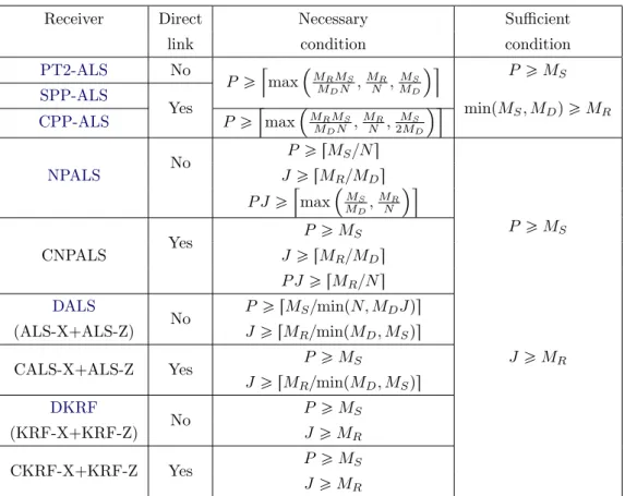
4.6 Summary of identifiability conditions . . . 78
4.7 Summary of uniqueness conditions . . . 79
5.1 Tensor-based receivers for two-hop one-way AF relaying systems . . . 82
List of Acronyms
AF Amplify-and-Forward
ALS Alternating Least Squares
BALS Bilinear ALS
BER Bit Error Rate
CF Compress-and-Forward
CPP-ALS Combined PARAFAC/PARATUCK2
CSI Channel State Information
DALS Double ALS
DF Decode-and-Forward
DFT Discrete Fourier transform
DKRF Double Khatri-Rao Factorization
DMT Diversity-multiplexing trade-off
FSK Frequency-Shift Keying
HOSVD Higher-Order Singular Value Decomposition
KRST Khatri-Rao Space-Time
LS Least Squares
LSKRF Least Squares Khatri-Rao Factorization
MIMO Multiple-Input and multiple-Output
MMSE Minimum Mean Square Error
NMSE Normalized Mean Square Error
NP-AF Nested PARAFAC-based Amplify-and-Forward relaying
NPALS Nested PARAFAC-ALS
xiv List of Tables
PARAFAC PARallel FACtor
PSK Phase-Shift Keying
PT2-AF PARATUCK2-Based Amplify-and-Forward relaying
PT2-ALS PARATUCK2-ALS
QAM Quadrature Amplitude Modulation
RD Relay-Destination
SD Source-Destination
SDF Selective Decode-and-Forward
SNR Signal-to-Noise Ratio
SPP-ALS Sequential PARAFAC/PARATUCK2
SR Source-Relay
SRD Source-Relay-Destination
ST Space-Time
STB Space-Time Block
STF Space-Time-Frequency
STT Space-Time Trellis
SVD Singular Value Decomposition
TST Tensor Space-Time
VD Vandermonde
Notation
In this thesis the following conventions are used. Scalar variables are denoted by
upper-case letters ♣A, B, . . .q, vectors are written as boldface lower-case letters ♣a,c, . . .q, matrices correspond to boldface capitals ♣A,B, . . .q, and tensors are written as calligraphic letters
♣A,B, . . .q. The meaning of the following symbols are, if nothing else is explicitly stated:
C set of complex-valued numbers
CI set of complex-valued I-dimensional vectors
CI✂J set of complex-valued (I✂J)-matrices
CI1✂☎☎☎✂IN set of complex-valued (I
1✂ ☎ ☎ ☎ ✂IN)-tensors
a✝ complex conjugate of aPC
⑤a⑤ modulus of a
⑥a⑥2 l-2 norm of a
AT transpose of A
AH Hermitian transpose of A
A✁1 inverse of A
A✿ Moore-Penrose pseudo-inverse of A
⑥A⑥F ♣⑥A⑥Fq Frobenius norm of A♣Aq
IN Identity matrix of dimensionN ✂N
1N1✂N2 All-ones matrix of dimensionN1✂N2
0N1✂N2 All-zeros matrix of dimensionN1✂N2
Ai1,i2 ✏ai1,i2 ♣i1, i2q-th element of matrix A
Ai1☎ ♣A☎i2q i1-th row (i2-th column) ofA Ai1,i2,i3 ✏ai1,i2,i3 ♣i1, i2, i3q-th element of tensor A
A❜B The Kronecker product ofA withB,
A☞B The Khatri-Rao (column-wise Kronecker) product.
A✆B The Hadamard product ofA withB,
vec(A) The vectorization operator.
Di♣A) Diagonal matrix with diagonal entries given by ith row of A
Et.✉ Expected value of its argument
Contents
1 Introduction 1
1.1 Un bref aper¸cu des communications sans fil . . . 1
1.2 R´eseau coop´eratif avec relais . . . 2
1.3 La mod´elisation tensorielle pour les communications coop´eratives avec relais . 3 2 Introduction 7 2.1 A brief overview of wireless communications . . . 7
2.2 Cooperative relay networks . . . 8
2.2.1 Network topology . . . 9
2.2.2 Forwarding protocol . . . 11
2.3 Tensor modeling for relay-based cooperative wireless communications. . . 12
2.4 Thesis organization and contributions . . . 15
3 Tensor decompositions 21 3.1 Fundamentals of tensors . . . 21
3.1.1 Tensor definitions. . . 22
3.1.2 Matricization . . . 24
3.2 Tensor decompositions . . . 25
3.3 PARAFAC decomposition . . . 26
3.4 PARATUCK2 decomposition . . . 28
3.5 Nested PARAFAC decomposition . . . 33
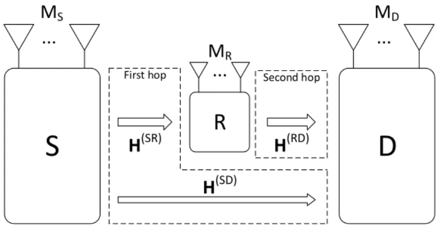
4 Tensor-based systems and their semi-blind receivers 39 4.1 Source transmission . . . 39
4.2 Model of the relay-assisted link (SRD). . . 43
4.2.1 PARATUCK2-based amplify-and-forward relaying (PT2-AF) . . . 44
4.2.2 Nested PARAFAC-based amplify-and-forward relaying (NP-AF) . . . 46
4.3 Noise degradation . . . 49
4.4 Semi-blind receivers . . . 50
4.4.1 Iterative receivers (ALS-based) . . . 50
4.4.2 Non-iterative receivers (SVD-based) . . . 51
4.5 Direct link: SVD-based receiver (PARAFAC-SVD) . . . 52
4.6 PT2-AF receivers . . . 54
4.6.1 PARATUCK2-ALS (PT2-ALS) . . . 54
xviii Contents
4.6.3 Identifiability conditions of the PT2-AF receiver . . . 57
4.6.4 Uniqueness conditions for the PT2-AF receivers. . . 59
4.7 NP-AF receivers . . . 63
4.7.1 Nested PARAFAC using ALS (NPALS) . . . 63
4.7.2 NP-AF two-step receivers . . . 64
4.7.3 NP-AF with direct link . . . 68
4.7.4 Identifiability conditions of NP-AF receivers. . . 70
4.7.5 Uniqueness conditions for the NP-AF receivers . . . 73
4.8 Computational cost. . . 75
4.9 Summary of the chapter . . . 77
5 Simulation analysis of the semi-blind receivers 81 5.1 Supervised estimation . . . 81
5.1.1 BALS channel estimator . . . 82
5.1.2 LS-SVD channel estimator . . . 83
5.2 Analysis of the transmission schemes . . . 84
5.2.1 Transmission rate. . . 87
5.2.2 Impact of source code length (P) . . . 88
5.2.3 Impact of relay code length (J) . . . 91
5.2.4 Impact of number of antennas (MD,MR,MS) . . . 93
5.3 Analysis of the semi-blind receivers . . . 95
5.3.1 Impact of the direct link on initialization . . . 96
5.3.2 PT2-AF receivers. . . 98
5.3.3 NP-AF receivers . . . 100
5.4 Summary of the chapter . . . 107
6 Conclusion 111
7 Conclusion 115
A Properties of matrix operations 119
B Channel scaling ambiguities 121
Bibliography 123
Chapter 1
Introduction
1.1
Un bref aper¸cu des communications sans fil
Dans la perspective sur communications sans fil, les utilisateurs mobiles sont sont
constam-ment ´echangent des donn´ees `a t`es haut d´ebit, comme par les services de multim´edia et les applications interactives. Pour r´epondre `a la demande continue pour les taux de transmission
plus ´elev´es avec une grande fiabilit´e du signal, Claude E. Shannon avait indiqu´e la n´ecessit´e d’augmenter les capacit´es des canaux de communication. En raison de l’attenuation du sig-naux envoy´e `a l’air libre, l’augmentation de la capacit´e de canal en utilisant une puissance
d’´emission ´elev´ee ou encore une bande passante plus large ne sont pas souhaitable, une fois que ces deux ressources sont peu abondants et limit´ees par des contraintes op´erationnelles,
comme la consommation d’´energie et l’attribution du spectre r´eglement´e. Au cours des deux derni`eres d´ecennies, une alternative `a augmenter les performances d’un lien sans fil a ´et´e
d’utiliser des techniques de diversit´e. Ces techniques permettent le r´ecepteur d’avoir des r´epliques de la message originale. Dans ce sens, si une r´eplique du signal a t profondment attnue, les autres peuvent avoir des att´enuations plus l´egeres. Dans les syst`emes de
commu-nication sans fil, les diversit´es de signaux sont g´en´eralement detemps,fr´equenceet deespace
[1,2].
En particulier pour la diversit´e spatiale, les r´epliques de signaux sont caus´ees en g´en´eral par la propagation par multi-trajets. Des nombreuses r´eflexions et r´efractions rencontr´ees
par les signaux cr´eent de nombreuses versions non corr´el´ees de la message d’origine, de sorte que plusieurs antennes au niveau du r´ecepteur peuvent les exploiter pour am´eliorer
l’estimation de symbole - ce qui est not´ee de gain de diversit´e. D’autre part, l’augmentation du nombre d’antennes `a l’´emission permet ´egalement un plus grand nombre de symboles ˆetre
envoyer simultan´ement, ce qui augmente le taux de transmission - en donnant un gain de multiplexage. De nombreux travaux ont ´et´e consacr´es `a maximiser l’un de ces gains, car il est un compromis naturel entre la fiabilit´e (gain de diversit´e) et le taux de transmission (gain
de multiplexage), c’est-`a-dire l’utilisation de plusieurs antennes `a l’´emetteur pour envoyer plusieurs versions d’un mˆeme symbole ou multiplexer plusieurs symboles diff´erents en mˆeme
2 Chapter 1. Introduction
deux derni`eres d´ecennies.
Malgr´e les avantages de la diversit´e spatiale par multiples antennes, dans de nombreuses
cas il est difficile d’avoir plus d’une antenne dans un dispositif mobile en raison de l’interaction ´electromagn´etique entre les ´el´ements ´etroitement espac´es. Dans ce cas, les r´epliques de signaux associ´es `a diff´erents trajets de propagation deviennent corr´el´ees par le couplage par
induction mutuelle entre les antennes, ce qui r´eduit les avantages de l’emploi de la technique MIMO. Pour surmonter cela et d’autres questions, les syst`emes coop´eratifs ont ´et´e propos´e.
1.2
R´
eseau coop´
eratif avec relais
Dans les communications coopratives, deux ou plusieurs noeuds de transmission sont
com-bin´es pour augmenter la diversit´e et/ou le puissance du signal sur un noeud de r´eception. Parmi les diff´erentes formes de coop´eration, cela qui a re¸cu une attention particuli`ere de la communaut´e de recherche est la coop´eration par relais [3, 4, 5, 6, 7]. Pour les syst`emes
mobiles assist´ee par relais, multiples terminaux mobiles sont utilis´es pour cr´eer un syst`eme virtuel MIMO [8,9,10]. Par cons´equent, plusieurs noeuds d’une seule antenne peuvent
tra-vailler de mani`ere coordonn´ee pour propager un message commun `a un noeud de destination, et alors un r´eseau multi-antenne peut ˆetre ´emul´e, et les avantages de la diversit´e d’´emission
peuvent ˆetre atteints. En outre, lorsque les liens directs entre les sources et la destination sont profond´ement att´enu´es, des relais interm´ediaires peuvent ˆetre utilis´es pour att´enuer ce probl`eme en fournissant ´egalement un gain de puissance.
En g´en´eral, les strat´egies de coop´eration avec relais sont class´es de plusieurs fa¸cons, par
exemple:
• la topologie du r´eseau: la communication half-duplex ou full-duplex,one-way ou
two-way, nombre de relais, nombre de sauts de transmission, entre autres;
• le protocole de transfert: amplify-and-forward (AF)[11],decode-and-forward (DF)[12,
3,4], selective-decode-and-forward (SDF) [13] etcompress-and-forward (CF) [12].
Certains de ces classifications sont bri`evement expliqu´ees dans ce qui suit.
Par d´efinition, un relais full-duplex peut simultan´ement ´emettre et recevoir des signaux dans la mˆeme bande de fr´equences (par exemple, le temps ou la fr´equence), alors que le
relais half-duplex effectue ces deux proc´ed´es dans des bandes non chevauchantes. En raison de la difficult´e d’annuler des interf´erences propres au relais - le signal `a transmettre est
typiquement 150 dB plus fort que le signal re¸cu, comme soulign´e dans [13] - le relais full-duplex est habituellement peu pratique avec le technologies radio actuelles.
1.3. La mod´elisation tensorielle pour les communications coop´eratives avec
relais 3
deux phases non chevauchantes sont intrins`equement li´ees `a la notion de deux-sauts. Dans
la th´eorie des r´eseaux, un saut correspond `a la transmission d’un bloc de donn´ees d’un noeud `
a un autre, et donc dans un syst`eme de deux-sauts le premier saut correspond `a la pleine
r´eception des signaux par le relais `a partir d’un noeud source, et le seconde saut correspond `
a leur retransmission vers un noeud destination. Dans un sc´enario avec plusieurs relais, le
nombre de sauts est fonction du nombre de relais, de la fa¸con dont elles communiquent entre eux et ´egalement de l’orientation de la transmission – i.e. une transmission unidirectionnelle (one-way) ou bidirectionnelle (two-way) .
En raison de la pr´esence d’interf´erence propre, ´etant donn´e que les signaux re¸cus par chaque noeud contient une partie de sa propre information transmise, une partie de l’efficacit´e
de la communication bidirectionnelle est compromise. En th´eorie, l’interf´erence propre pour-rait ˆetre annul´ee, mais que le nombre de noeuds dans le r´eseau augmente, l’impact de
l’interf´erence propre devenue d´esastreuse, favorisant ainsi le d´eploiement de la transmission unidirectionnelle.
Le protocole de transmission est li´e au traitement de signal effectu´e par les relais, et ils sont en g´en´eral divis´es en r´eg´en´eratifs et non-r´eg´en´eratifs, ce qui signifie que le signal d’origine est r´ecup´er´e (“r´eg´en´er´ee ) au relais avant son renvoi au noeud suivant. Les repr´esentants les
plus importants de ces protocoles sont respectivement le decodage-and-forward (DF) et le
amplify-and-forward (AF).
L’exigence deu protocole DF est que le relais d´ecode avec succ`es les informations de la source, et donc le relais doit ˆetre adapt´ee `avecune structure capable de calcul pour une telle
tˆache. Pour r´eduire les coˆuts de mise en oeuvre et l’exploitation complexes de relais, une alternative est de d´eployer le protocole AF.
Amplifier-and-forward a ´et´e introduit en [11] et est le protocole le plus simple `a mettre en oeuvre, ce qui explique pourquoi il a re¸cu autant d’attention au cours des derni`eres ann´ees.
Il simplement amplifie le signal re¸cu au niveau du relais afin de lutter contre les pertes de trajet entre la source et la destination . En raison de sa transformation lin´eaire simple, les performances de ce protocole souffre du fait qu’il amplifie ´egalement les bruits et interf´erences
aux antennes de l’´equipement.
1.3
La mod´
elisation tensorielle pour les communications
coop´
eratives avec relais
Pour l’am´elioration de la qualit´e du signal, une autre forme pour am´eliorer les performances est par l’utilisation de techniques d’estimation aveugles. En g´en´eral, la d´etection de
4 Chapter 1. Introduction
estimation ne est faite en r´esolvant un syst`eme d’´equations bilin´eaires, o`u les coefficients de
canal sont les seules inconnues. Dans ce cas, l’estimation de canal est dit ˆetre supervis´e ou non-aveugle. Depuis une p´eriode de transmission est d´edi´ee uniquement `a l’estimation canal
ne correspondent pas aux informations de transmission, l’efficacit´e spectrale est r´eduit. En outre, si les coefficients d’´evanouissement de canal varient rapidement, son temps coh´erente
peut ˆetre trop court pour l’estimateur bas´e sur la formation d’estimer avec pr´ecision le CSI. Estimation aveugle arrive souvent alors quand les symboles transmis peuvent ˆetre d´etect´es au niveau du r´ecepteur, sans la n´ecessit´e de la CSI. Dans cette th`ese, estimation aveugle est
trait´e comme un synonyme pour l’estimation conjointe des symboles et des canaux. Bien que le CSI ne est pas n´ecessaire pour d´etecter les symboles avec un estimateur aveugle, sa
connaissance est importante pour une optimisation de transmission ´eventuelle.
Dans un sc´enario de relais, lorsqu’il est d´ecid´e d’employer le protocole AF, qui vise `a sim-plifier la charge de calcul dans les stations de relais, un algorithme de d´ecodage est utilis´ee `a la
destination seulement. Dans le contexte de syst`emes `a deux bonds `a sens unique, l’utilisation de techniques de pr´ecodage `a la source et / ou le relais n´ecessite g´en´eralement l’instantan´e CSI connatre le source-relais etrelay-destination canaux estimation de canal commune
-pour mener `a bien l’optimisation de transmission [14, 15, 16, 17]. Avec noeuds antennes multiples, des strat´egies fond´ees pilotes point-`a-point conventionnelles ne fournissent pas
d’estimation de canal `a la fois de houblon s´epar´ement `a la destination , depuis le AF proto-cole ne ´echelles les signaux, et donc la r´ecepteur ne peut estimer le produit des deux matrices de canal. Au cours des derni`eres ann´ees analyse tensorielle a ´et´e propos´e de rem´edier `a ce
probl`eme.
Cependant, en d´epit de l’int´erˆet croissant de l’utilisation de tenseurs pour le codage espace-temps, encore tr`es peu de travaux proposent des syst`emes `a base-tenseur pour les
communications coop´eratives. Seulement r´ecemment une analyse de tenseur est r´ev´el´e ˆetre une approche efficace pour l’estimation de canal et / ou la d´etection de symbole dans les
syst`emes de relayage de coop´eration [18,19,20,21,22,23].
Dans [24] (et plus tard dans [25, 26]) Lioliou et al. propos´e un, forme ferm´ee m´ethode supervis´ee pour estimer les deux canaux d’un aller simple AF syst`eme relayer avec des gains
variant dans le temps d’amplification. Bien que techniquement ces oeuvres ne exploitent pas les propri´et´es multidimensionnelles de tenseurs, des travaux bas´es tenseur-ont abord´e le mˆeme concept de gains de relais variant dans le temps de proposer des alternatives pour
r´esoudre le probl`eme d’estimation de canal dans les syst`emes coop´eratifs.
Ainsi, les quelques ´etudes concernant la mod´elisation de tenseur de coop´eration MIMO syst`emes se concentrent sur le probl`eme de l’estimation de canal en utilisant des s´equences de
1.3. La mod´elisation tensorielle pour les communications coop´eratives avec
relais 5
oeuvres [21, 22], o`u PARAFAC `a base de r´ecepteurs aveugles pour une multi-utilisateur de
liaison montante syst`eme coop´eratif sont propos´ees. Ces travaux int`egrent explicitement “ la coop´eration ” comme la troisi`eme dimension des donn´ees re¸cues en plus de l’espace (antennes
de r´eception) et de temps (p´eriodes de symbole) dimensions, qui se fait en regroupant les noeuds mono-antennes (utilisateurs et relais) en grappes. Cette approche inhabituelle a
limit´e l’efficacit´e spectrale, puisque seulement une grappe transmet `a la fois, tandis que les autres doivent rester silencieux.
Cette th`ese vise `a combler l’´ecart dans la litt´erature des aveugles-estimation utilisant
tenseurs pour les communications de relayage de coop´eration. Estimation conjointe des symboles et des canaux dans un syst`eme de communication AF `a deux bonds est possible en
adoptant le mˆeme variant dans le temps processus de relayer [24,18,20], mais le recours `a un KRST codant pour moduler les symboles `a la source au lieu de l’utilisation de s´equences
d’apprentissage orthogonales connues. Plus loin, nous vous proposons deux strat´egies de traitement diff´erentes au relais, afin que nous puissions exploiter le tenseur de donn´ees de r´eception soit comme un mod`ele de PARATUCK2 ou un mod`ele de PARAFAC imbriqu´ee,
deux pr´esentant les propri´et´es d’unicit´e essentiels n´ecessaires pour estimer aveugl´ement les param`etres d´esir´es. Ces deux sch´emas de transmission conduisent au d´eveloppement
Chapter 2
Introduction
Contents
2.1 A brief overview of wireless communications . . . 7
2.2 Cooperative relay networks . . . 8
2.3 Tensor modeling for relay-based cooperative wireless communications 12
2.4 Thesis organization and contributions . . . 15
2.1
A brief overview of wireless communications
In the long-standing perspective on the future of the wireless communications, mobile users are constantly sharing data that need high-bandwidth transfers, as services of real-time
multimedia and interactive applications. To meet the continuous demand for higher trans-mission rates and signal reliability, Shannon in [27] had stated the necessity of increasing the capacities of the communication channels. Due to signal fading through propagation in
open air, increasing channel capacity by employing a higher transmission power or a broader bandwidth is in general undesirable, once that both resources are scarce and limited by
op-erational constraints, such as energy consumption and regulated spectrum allocation. In the last two decades, an alternative to increase the performance of a wireless link was to use the diversity techniques. These techniques provide the receiver with replicas of the original
message experiencing uncorrelated propagation channels. In this sense, if a component of the signal is over a deep fading, caused for example by shadowing or path loss, other
compo-nents have a high probability of suffering a lighter attenuation. In wireless communication systems, signal diversities are commonly of: time, e.g. by transmitting sequences of
redun-dant bits; frequency, e.g. using spread spectrum techniques like direct-sequence (DS) and frequency-hopping (FH); andspace [?,2].
Particularly for spatial diversity, the replicas of the signals are caused in general by the
multi-path propagation. In a rich-scattering scenario, such as a densely urban area, countless reflexions and refractions experienced by the traveling signals create numerous uncorrelated
8 Chapter 2. Introduction
denoteddiversity gain. On the other hand, increasing the number of antennas at transmission
also lets a greater number of symbols to be sent simultaneously, increasing the transmission rate – providing multiplexing gain. Many works have been dedicated to maximizing one
of these gains, since there is a natural trade-off between reliability (diversity gain) and transmission rate (multiplexing gain) [28], i.e. using multiple antennas at the transmitter to
send multiple versions of a same symbol or multiplexing several distinct symbols at the same time. In all cases, the technique of employing multiple antennas at both transmitter and receiver is called Multiple-Input and multiple-Output (MIMO), and it has revolutionized the modern wireless communications in the past two decades.
Indeed, since the fundamental works of Foschini [29] and Telatar [30] on the benefits
of multiple antennas on the channel capacity, uncountable works have decided to exploit one or more diversities in conjunction with the spatial diversity. A prominent field arose
in the development of the space-time coding techniques. As the name suggests, time and space (antenna) diversities are combined, providing a welcoming flexibility to deal with the Diversity-multiplexing trade-off (DMT).
Early works on multiple antennas at the transmitter were done by Guey et al. [31] and by Foschini [32], and Tarokh et al. [33,34] proposed a class of Space-Time Trellis (STT) codes, which could performed excellently in terms of symbol detection, but at a high complexity cost at the receiver due to the need of a Viterbi decoder. To address this issue, Alamouti
in [35] introduced what is called nowadays as Space-Time Block (STB) coding [36,37], by presenting a simple scheme using two transmit antennas and a single receive antenna to achieve full transmit diversity and full rate, yet having a linear decoding.
In spite of all benefits from exploiting the spatial diversity with arrays of multiple an-tennas, in many occurrences it is difficult to have more than one of them in a small mobile
terminal, mainly due to the electromagnetic interaction between the closely-spaced radiating elements. In this case, the signal replicas associated with different propagation paths become
correlated by the mutual coupling between the antennas, reducing the benefits of employing theMIMOtechnique. To overcome this and other issues, the use of thecooperative diversity
was proposed [38,13,39,9].
2.2
Cooperative relay networks
In cooperative communications, two or more transmitting nodes are combined to increase
signal diversity and/or power at a receiving node. Among the different forms of cooperation, one that has received special attention from the research community is the cooperative
2.2. Cooperative relay networks 9
station are used to create a virtualMIMOsystem [8,9,10]. Therefore, several single antenna nodes can work coordinately to propagate a common message to a destination node, so a multiple antennas array can be emulated, and the benefits of the transmit diversity can be
achieved. In addition, when the direct links between the sources (co-channel users) and the destination (base station) are deeply attenuated, intermediate relay stations can be used to
mitigate this issue by providing also a power gain. Besides, many works have also pointed out the benefits of relaying networks on reducing energy waste in broadcasting transmissions ([40] and references therein). In an era where the number of wireless devices increases tirelessly,
in which concepts as Internet of Things propose a revolution on how people and machines interact, exploiting a large ensemble of collaborative nodes – referred as user-cooperation
in [41] – to enhance the connectivity sounds a sure step into the envisioned decentralized networks of the future [42,43,44,45].
Although relaying systems were extensively used in analog radio and television broadcast in the past, its interest in wireless communications suffered an abrupt reduction after the early 80’s. Van der Meulen in [46,47] was the first one to study the capacity of the
three-terminal relay channel, further investigated by Cover and El Gamal in 1979 [12]. Until the end of 90’s, there were sparse contributions on relaying networks, but remarkable advances
in wireless communications, such as the previously mentioned derivation of the capacity of multi-antenna systems by [29,30] and the development of space-time codes in [33,34,36,37,
35,32]. These advances have given a new lease of life to relaying in digital communications,
and now a much larger body of research is available in the literature, for example in the areas of relay selection [48,49], relay beamforming [50] and cooperative secrecy [51].
In general, relaying strategies are classified in many ways, e.g.:
• the network topology: full- or half-duplex communication, one- or two-way orientation,
number of relays, number of transmission hops, among others;
• the forwarding protocol: e.g. Amplify-and-Forward (AF) [11], Decode-and-Forward (DF) [12,?,4], Selective Decode-and-Forward (SDF) [13] and Compress-and-Forward (CF) [12].
Some of these classifications are briefly explained in the following.
2.2.1 Network topology
By definition, a full-duplex relay can simultaneously transmit and receive signals in the same
band (e.g. time or frequency), while the half-duplex relay performs these two processes in non-overlapping bands. Due to the difficulty of canceling (self-)interference at the relay – the
10 Chapter 2. Introduction
U1 R U2
Figure 2.1: Two-way half-duplex relaying
S R D
Figure 2.2: One-way half-duplex relaying
In general, half-duplex relays do not operate reception and transmission at the same time.
In a scenario with only one relaying process between two nodes, these two non-overlapping phases are inherently linked to the concept of dual-hoping (or two-hop). In network theory,
a hop corresponds to the transmission of a block of data from one node to another, and thus in a two-hop relaying the first hop corresponds to the full reception of the signals by the relay from a source node, and the second hop corresponds to their subsequent retransmission to
a destination node. In a scenario with multiple relays, the number of hops depends on the number of relays, on how they communicate among each other and also on the orientation
of the transmitted message– i.e. one-way or two-way.
The two-way communication channel was first introduced by Shannon in [52] to enable
simultaneous bidirectional communication, but it was mostly in the past decade that two-way systems in relay networks started receiving the deserved attention from the research
community ([53] and references therein). A conventional two-way half-duplex system is shown in Fig 2.1. Two nodes (U1 and U2) send their signals to the relay R in the first hop (black arrow), which forwards a (mixed) version of such signals back to the origin nodes in
the second hop (white arrow).
Due to the presence of self-interference, given that the signals received by each node contains a portion of its own transmitted information, part of the efficiency of the two-way communication is compromised. In theory, self-interference could be canceled out, but as
the number of nodes in the network increases – as in the case of large ad hoc networks – the impact of the self-interference become disastrous, thus favoring the deployment of one-way
relaying. The one-way system is shown in Fig. 2.2, where S denotes a source of information, and D denotes a destination node.
2.2. Cooperative relay networks 11
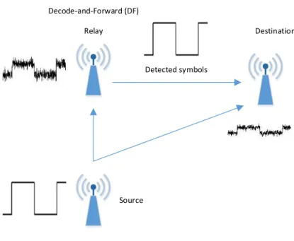
Relay Destination
Source Decode-and-Forward (DF)
Detected symbols
Figure 2.3: Decode-and-forward (DF) protocol
scenario (with full elimination of self-interference by the nodes), the two-way protocol cor-responds to the superimposition of two one-way transmissions (U1 Ñ R Ñ U2 and U1 Ð
RÐ U2). Thus, the two-way system can convey information in two hops what the one-way system does in four.
2.2.2 Forwarding protocol
The forwarding protocol is related to the signal processing performed by the relays, and
they are in general divided into the regenerative and non-regenerative classes, which means whether the original signal is recovered (“regenerated”) at the relay prior to its forwarding to
the following node. The most important representatives of regenerative and non-regenerative protocols are respectively the decode-and-forward (DF) and the Amplify-and-forward (AF). Decode-and-forward (DF) is a protocol where the relay performs decoding and re-coding
of the signals before forwarding the data to the receiver. The general concept of the DF
protocol was firstly introduced by Cover and Gamal [12] and later redefined in [?, 4]. An illustrative scheme of theDF protocol with a single relay and a direct link is shown in Fig.
2.3, expressing the signal sent to the destination by the relay as a recovered version of the signal sent by the source.
The requirement for an efficient cooperation in this protocol is that the relay successfully
12 Chapter 2. Introduction
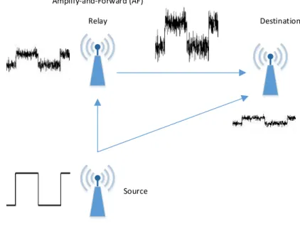
Relay Destination
Source Amplify-and-Forward (AF)
Figure 2.4: Amplify-and-forward (AF) protocol
operating complex relaying stations, an alternative is to deploy the AFprotocol.
Amplify-and-forward was introduced in [11] and is the simplest protocol to implement, which explains why it has received so much attention from the academia and the industry
in the past few years. It simply amplifies the received signal at relay in order to combat the path losses between the source and the destination. Due to its simple linear processing, the
performance of this protocol suffers from the fact that it also amplifies noises and eventual interferences at the antennas of the relay, as shown in Fig. 2.4.
2.3
Tensor modeling for relay-based cooperative wireless
communications
It was mentioned in this chapter that increasing signal strength, bandwidth and employing diversity techniques are common means to improve a wireless link. Another form to enhance
performance is through the use of blind estimation techniques. In general, symbol detection at a receiver requires the knowledge of the Channel State Information (CSI). Conventionally, the channel matrices are estimated by using sequences of training (pilot) symbols, so CSI
estimation is done by solving a system of bilinear equations, where the channel coefficients are the only unknowns. In this case, the channel estimation is said to be supervised or non-blind.
2.3. Tensor modeling for relay-based cooperative wireless communications 13
channel vary rapidly, its coherent time may be too short for the training-based estimator to
accurately estimate the CSI. Blind estimation usually happens then when the transmitted symbols can be detected at the receiver without the need of the CSI. In this thesis, blind estimation is treated as a synonymous for joint estimation of symbols and channels. Although the CSI is not necessary to detect the symbols with a blind estimator, its knowledge is important for an eventual transmit optimization.
In a relaying scenario, when it is decided to employ the AF protocol, which aims to simplify the computational burden at the relay stations, a decoding algorithm is used at the
destination only. In the context of two-hop one-way systems, the use of precoding techniques at the source and/or the relay generally requires the instantaneous CSI knowledge of both
source-relayandrelay-destinationchannels – joint channel estimation – to carry out transmit
optimization [14,15,16,17]. With multiple-antenna nodes, conventional point-to-point pilot-based strategies do not provide channel estimation of both hops separately at the destination,
since the AF protocol only scales the signals, and thus the receiver can only estimate the product of the two channel matrices. In recent years tensor analysis has been proposed to overcome this issue.
For point-to-point (non-cooperative) multiple-antenna communication systems, tensor-based methods have been proposed in a number of works [54,55,56,57] to solve the problem of blind estimation. In those cases, the dimensionality of a tensor is usually linked to a
number of diversities to be exploited (e.g. space, time, frequency and code).
Sidiropoulos et al. in [54] for the first time applied tensor decompositions in telecom-munications. By modeling a multiuser point-to-point DS-CDMA system using the PARallel
FACtor (PARAFAC) tensor model [58,59],both symbol and channel matrices could be ointly estimated at the receiver.
This innovative approach in signal processing casted a light on the possibilities of using
tensor analysis on several other applications. Until then tensor decompositions were mostly restricted to evaluate empirical data in psychometrics and chemometrics (e.g. [58,60]).
Fol-lowing [54], Sidiropoulos also developed the flexible class of Khatri-Rao Space-Time (KRST) codes based on thePARAFAC tensor model [61].
De Almeida et al. [56] modeled a transmission scheme based on two allocation matrices
for selection of antennas and data streams. There, the set of received signals could be organized in a third-order tensor data following a PARATUCK2 decomposition [62, 60]. Other tensor-based transmission schemes also approached the use of allocation matrices, as
the Tensor Space-Time (TST) coding [63], which introduced a more complex scheme than [56] by resorting to a more general tensor model, i.e. PARATUCK-♣2,4q; and the
14 Chapter 2. Introduction
More recently, [64] proposed the Double Khatri-Rao space-time-frequency (D-KRSTF)
coding scheme, based on the nested PARAFAC tensor decomposition introduced therein, where a fourth-order tensor could be written by the combination of two third-order
PARAFACmodels.
The different ways of designing the transmission schemes led to different tensor mod-els for the received signals (e.g. PARAFAC, PARATUCK2, PARATUCK-(2,4) and nested PARAFAC), each system having its own interesting properties. For all these non-cooperative transmission schemes, new blind receivers were proposed to allow a joint symbol and channel estimation without requiring pilot sequences for CSI acquisition. For more comprehensive and detailed presentation of the use of tensors in wireless communications, please see [65,66].
However, despite of the growing interest of using tensors for space-time coding, still very few works propose tensor-based systems for cooperative communications. Only recently
tensor analysis has shown to be an efficient approach for channel estimation and/or symbol detection in cooperative relaying systems [18,19,20,21,22,23].
In [24] (and later in [25,26]) Lioliou et al. proposed a supervised, closed-form method to
estimate both channels of a one-wayAFrelaying system with time-variant amplifying gains. Although technically these works do not exploit the multidimensional properties of tensors,
tensor-based works have approached the same concept of time-variant relay gains to propose alternatives to address the channel estimation issue in cooperative systems.
In the works [18,19,20] the signals collected at the destination node through a number of time-blocks are stored in third-order tensors that follow the PARAFAC model. In [18,
19], a tensor formulation is applied to two-way MIMO relaying systems, and the channels are estimated by firstly canceling self-interference in each node, and then by solving the
estimation itself in an algebraic manner similar to [24].
The approach proposed in [20] also allows a simultaneous estimation of the both partial channels in a one-way scenario, but uses an Alternating Least Squares (ALS) algorithm instead. Relying on a mild condition to ensure the essential uniqueness of the PARAFAC
decomposition [67], the use of this iterative algorithm provided less constrained identifiability conditions than its competitor [24], leading to an eventual gain in spectral efficiency in some
scenarios.
Another iterative method for channel estimation was recently proposed in [23]. Although innovative in the proposal of a supervised channel estimation in a three-hop system, the
Tucker2 tensor model adopted therein has no inherent properties of uniqueness of its solution, so a very restrictive relaying strategy is employed, where the receiver needs to combine the
signals from two (intersecting) paths (one of them following a PARAFACmodel) to proper estimate the channels.
2.4. Thesis organization and contributions 15
the problem of channel estimation using training sequences, leaving aside the intrinsic
ben-efits of the blind estimation, already exploited by tensor-based methods for non-cooperative systems. The exceptions are the works [21, 22], where PARAFAC-based blind receivers for an uplink multiuser cooperative system are proposed. These works explicitly incorporate “cooperation” as the third dimension of the received data in addition to space (receive
an-tennas) and time (symbol periods) dimensions, which is done by grouping single-antenna nodes (users and relays) in clusters. This unusual approach has limited spectral efficiency, since only one cluster transmits at a time, while the others must stay silent.
By looking at these different cooperative schemes, we can see that the trilinearPARAFAC
decomposition is not suitable to model a system with joint symbol and channel estimation in
MIMO AFrelaying networks. Therefore, to employ more complex STcoding at source and to enable blind-estimation in these scenarios, it is needed to resort to more complex tensor models.
This thesis intends to fill the gap in the literature of blind-estimation using tensors for
cooperative relaying communications. Joint estimation of symbols and channels in a two-hop
AFcommunication system is possible by adopting the same time-variant relaying process of [24,18,20], but resorting to aKRSTcoding to modulate the symbols at the source instead of using known orthogonal training sequences. Further on, we propose two different processing strategies at the relay, so we can exploit the receiving data tensor either as a PARATUCK2
model or a nested PARAFAC model, both presenting the essential uniqueness properties necessary to blindly estimate the desired parameters. These two transmission schemes lead
to the development of a variant of semi-blind receivers, which are studied in terms of their identifiability conditions, computational complexities and performances.
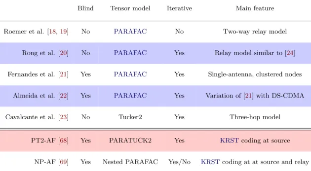
A summary of the state of the art tensor-based methods for Amplify-and-Forward (AF) cooperative systems is presented in Table 5.1.
2.4
Thesis organization and contributions
Besides the introduction and conclusion chapters, the thesis manuscript is organized into 4
main chapters, whose content and contributions are briefly described below:
Chapter 2. Important fundamentals of tensors are treated in this chapter, followed by the presentation of three tensor decompositions (i.e. PARAFAC, PARATUCK2 and nested PARAFAC) and their essential uniqueness properties.
The contribution presented in this chapter is the derivation of two new essential
16 Chapter 2. Introduction
Blind Tensor model Iterative Main feature
Roemer et al. [18,19] No PARAFAC No Two-way relay model
Rong et al. [20] No PARAFAC Yes Relay model similar to [24]
Fernandes et al. [21] Yes PARAFAC Yes Single-antenna, clustered nodes
Almeida et al. [22] Yes PARAFAC Yes Variation of [21] with DS-CDMA
Cavalcante et al. [23] No Tucker2 Yes Three-hop model
PT2-AF [68] Yes PARATUCK2 Yes KRSTcoding at source
NP-AF [69] Yes Nested PARAFAC Yes/No KRSTcoding at at source and relay
Table 2.1: State of the art tensor-based works for AF relaying systems
ambiguity issues.
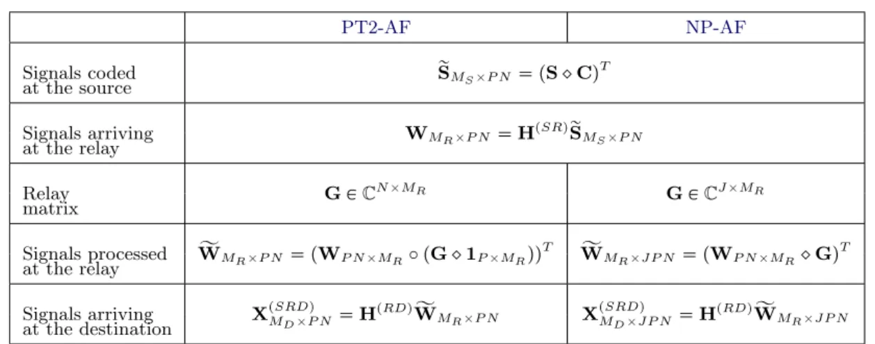
Chapter 3. This chapter contains the largest body of contributions of this thesis, which concerns the development of new tensor-based transmission schemes for a one-way relaying system and of semi-blind receivers adapted to them.
Employing a simplifiedKRSTcoding at source, two differentAFrelaying strategies lead to the following transmission protocols:
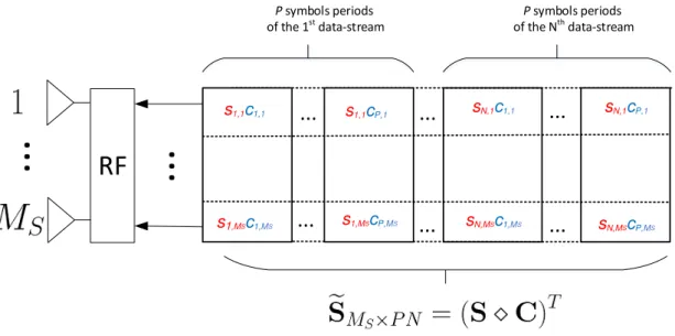
• PARATUCK2-Based Amplify-and-Forward relaying (PT2-AF): the time-varying na-ture of the relay AFprocessing is defined by the existence of time frames, where each frame corresponds to the amplifying gains associated with a specific data-stream trans-mitted by the source. The receiving signal tensor at destination follows a PARATUCK2
model .
• Nested PARAFAC-based Amplify-and-Forward relaying (NP-AF): Instead of associ-ating each time-frame with a data-stream, the relay performs another KRST coding, spreading the whole block of signals into another time domain (dimension). The data
tensor is not longer modeled by a third-order PARATUCK2 model, but following the fourth-order nested PARAFAC model.
A number of semi-blind receivers adapted to these proposed schemes are presented in the
2.4. Thesis organization and contributions 17
• PARATUCK2-ALS (PT2-ALS): This receiver estimates symbol and channels using an
ALSalgorithm;
• Sequential PARAFAC/PARATUCK2 (SPP-ALS): Similar toPT2-ALS, but uses as an initialization for the ALSalgorithm the symbols estimated from signals received from a direct link. The name of this receiver comes from the fact this symbol initialization is obtained by exploiting aPARAFACmodel as in [61];
• Combined PARAFAC/PARATUCK2 (CPP-ALS): In this receiver, the direct link is not used only for symbol initialization, but also provides additional spatial diversity
for symbol estimation at each iteration of the algorithm.
For the NP-AFtransmission scheme, the semi-blind receivers are:
• Nested PARAFAC-ALS (NPALS): As inPT2-ALSreceiver, symbols and channels are estimated with a singleALSprocess;
• Double ALS (DALS) and Double Khatri-Rao Factorization (DKRF): Each of these is a two-step receiver, formed by either iterative (i.e. DALS) or non-iterative (i.e.
DKRF) routines. In both cases, the first step (ALS-X or KRF-X) estimates, from the signals received through the relay link, the symbols and also the compound channel
between the source and destination. The second step (ALZ-Z or KRF-Z) corresponds then to extracting from this channel the individual channels that compose the two-hop
network.
• CNPALS, CALS-X and CKRF-X: The presence of the direct link can also be used in the NP-AF protocol to improve the semi-blind estimation, in the same way that
SPP-ALS and CPP-ALS are variants to PT2-ALS. The routines CNPALS, CALS-X and CKRF-X substitute respectivelyNPALS, ALS-X and KRF-X for a better symbol estimation.
The hybrid receivers, called in this way due to jointly exploit the direct and relay-assisted
links, rather than simply combining both links for a better symbol estimation, lead to a refinement of the channel estimates. This is a remarkable feature not possible with the supervised techniques.
The relationship between the tensor models, the transmission protocol and the semi-blind receivers are depicted in Fig. 2.5.
18 Chapter 2. Introduction
PT2-AF NP-AF
PT2-ALS
SPP-ALS
CPP-ALS
NPALS
DKRF
CALS-X DALS
CNPALS
CKRF-X Direct link
model
Nested PARAFAC
PARATUCK2 PARAFAC
T
e
n
so
r
m
o
d
e
ls
T
ra
n
sm
issi
o
n
p
ro
to
co
ls
S
e
m
i-b
lin
d
re
ce
ive
rs
Figure 2.5: Tensor-based transmission protocols and their semi-blind receivers
are evaluated through the utilization of a Zero-Forcing (ZF) receiver with perfect CSI. In addition, all semi-blind receivers for the new one-way relaying schemes are studied in terms of its computational cost and also in terms of Bit Error Rate (BER) and channel Normalized Mean Square Error (NMSE). Comparisons with other state-of-the-art supervised methods are done through extensive use of Monte Carlo computational experiments.
2.4.1 Publications
Part of this work in this thesis was, or soon will be, published in the following publications.
• Journal papers:
1. L. R. Ximenes, G. Favier, A. L. F. de Almeida, and Y. C. B. Silva,
2.4. Thesis organization and contributions 19
2. L. R. Ximenes, G. Favier, and A. L. F. Almeida, “Semi-blind receivers for
non-regenerative cooperative MIMO communications based on nested PARAFAC mod-eling,” Accepted with major revisions to IEEE Transactions on Signal Processing.
3. L. R. Ximenes, G. Favier, and A. L. F. Almeida, “Closed-form semi-blind receiver for
two-hop MIMO relay systems using a double Khatri-Rao space-time coding,” To be submitted to IEEE Signal Processing Letters, 2015.
• Conference paper:
1. L. R. Ximenes, G. Favier, and A. L. F. Almeida, ”MMSE-based blind-receiver for one-way relay-assisted MIMO communications,” in preparation to be submitted to
Brazilian Telecommunications Society (SBrT) conference, 2015.
• Participation in journal paper (Subject not belonging to this thesis manuscript):
1. A. L. F. de Almeida, G. Favier, and L. R. Ximenes, “Space-time-frequency
(STF) MIMO communication systems with blind receiver based on a generalized PARATUCK2 model,” IEEE Transactions on Signal Processing, vol. 61, no. 8, pp.
Chapter 3
Tensor decompositions
Contents
3.1 Fundamentals of tensors . . . 21
3.2 Tensor decompositions . . . 25
3.3 PARAFAC decomposition . . . 26
3.4 PARATUCK2 decomposition . . . 28
3.5 Nested PARAFAC decomposition . . . 33
In this chapter, some fundamentals of tensors that are necessary for the comprehension of this thesis are introduced. The chapter is divided into a first part, containing the concept of
tensor itself and the so-called process of matricization of a tensor, while the second part deals with the tensor decompositions to be used in the later chapters, namelyPARAFAC[58,59], PARATUCK2 [62,70] and nested PARAFAC [64]. When addressing these last two tensor decompositions, the first contributions of this work are presented. For the PARATUCK2 model, a theorem concerning design rules of the matrix factors is proposed to eliminate
arbitrary column permutations of their solutions, and for the nested PARAFAC model the new contributions are given in the form of two theorems involving its uniqueness properties.
Other important properties and operators of multilinear algebra, such as the Kronecker and Khatri-Rao products, are confined in AppendixA.
3.1
Fundamentals of tensors
This section is divided into two subsections. The first addresses the definition of tensors, as
well as the definitions of the mode-nproduct and of the tensor rank. The second subsection deals exclusively with the matricization process, which consists in organizing the entries of a higher order tensor into a matrix.
Before introducing the fundamentals of tensors, it is important to present the definition of the Kruskal rank (k-rank). The concept of Kruskal rank was proposed by Kruskal in his
22 Chapter 3. Tensor decompositions
Definition 1. (Kruskal rank (k-rank)) The Kruskal rankkXis the maximum
num-ber such that any subset of kX columns ofX are linearly independent. Some of its
properties are:
• 0↕kX↕rank♣Xq;
• ifX has any two or more linearly dependent non-zero columns, then kX✏1;
• if and only if X has one or more zero columns, thenkX✏0;
• if X is a full column rank matrix, then kX✏rank♣Xq;
• if the elements of X are independently drawn from a continuous Gaussian distribution, then kX✏rank♣Xq.
Indeed, the comprehension of the Kruskal rank is primordial to fully understand the uniqueness properties of the tensor decompositions shown more ahead. Another useful
prop-erty involving the k-rank is the lemma presented in [71,72] and restated here.
Lemma 1. For A PCL✂M and B P CN✂M, the Khatri-Rao product A☞B is full column
rank if
kA kB ➙M 1, (3.1)
where kX is k-rank of X.
3.1.1 Tensor definitions
A N-way1 orNth-order tensor is a multilinear array of dimensionalityN. More commonly,
tensors are referred only to arrays of order greater than two, also denoted higher-order tensors, since first-order and second-order tensors are better known as vectors and matrices, respectively. Thus, a third-order tensor has three dimensions (or modes), and perhaps its
best geometric representation would be as shown in Fig.3.1.
In general, higher-order tensors adopt definitions that are directly generalized from
ma-trices. For example, an entry of a tensor can be referenced in a similar manner to those of a matrix, and the Frobenius norm of a tensor follows the conventional definition of the Frobenius norm of a matrix.
Another important mathematical operation within multilinear algebra is called mode-n
product:
1
3.1. Fundamentals of tensors 23
Figure 3.1: Third-order tensor X PCI1✂I2✂I3
Definition 2. (Mode-n product) Given a tensor X P CI1✂I2✂☎☎☎✂In✂☎☎☎✂IN, the
mode-n product of this tensor and matrix U P CJ✂In is denoted by X ✂
n U P
CI1✂☎☎☎In✁1✂J✂In 1✂☎☎☎IN, and this operation yields
♣X✂nUqi1☎☎☎in✁1,j,in 1☎☎☎iN ✏
IN
➳
in✏1
xi1☎☎☎in✁1,in,in 1☎☎☎iNuj,in. (3.2)
In addition, for any indices 1↕m↕N and1↕n↕N, it holds that
X ✂mA✂nB✏X ✂nB✂mA. (3.3)
A mode-n product is thus nothing but a linear transformation of the tensor along its nth
mode. Further on, expressing the tensor decompositions using the mode-n product will be shown as an useful way to understand them in terms of their factors.
Before moving forward into the process of matricization, it is also important to compre-hend the definition of tensor rank:
Definition 3. (Tensor rank) The rank ofX is defined by the minimum number of rank-one tensors that generate X as their sum.
The notion of tensor rank was firstly introduced by Hitchcock in 1927 [73], and then later it was independently proposed by Kruskal in [67]. This definition of tensor rank is
consis-tent with the definition of the matrix rank, where R is the smallest number of rank-one matrices that form a rank-R matrix. In the case of a tensor, a rank-one N-order tensor
X PCI1✂I2✂☎☎☎✂IN can be defined byN vector outer products, i.e.
xi1,i2,☎☎☎,iN ✏a
♣1q
i1 a
♣2q
i2 ☎ ☎ ☎a
♣Nq
iN , (3.4)
wherea♣inq
n is i
th
n element of the vectora♣nqPCIN✂1.
24 Chapter 3. Tensor decompositions
3.1.2 Matricization
The process of matricization (or unfolding) of a tensor corresponds to organizing its elements in a matrix, usually by concatenating side-by-side the so-called matrix slices.
Given a third-order tensor X P CI1✂I2✂I3, the horizontal, lateral and frontal slices are denoted by Xi1☎☎ PC
I2✂I3,X
☎i2☎PC
I3✂I1 and X
☎☎i3 PC
I1✂I2, respectively. Theith
1 horizontal
Frontal slices Horizontal slices Lateral slices
Figure 3.2: Slicing ofX
slice is obtained by fixing the (first-mode) index i1 and varying i2 and i3, and equivalent
procedures are done to find the lateral and frontal slices. The frontal, horizontal and lateral slices of a third-order tensor are illustrated in Fig. 3.2.
In the literature, there are multiple ways to define an unfolding of a tensor, according, for example, to the indexing order of the elements of the resulting matrix. However, in all definitions the mode-n unfolding of a tensor X P CI1✂☎☎☎In☎☎☎✂IN is characterized by having
one of its dimension equal to In. For simplification, we refer to mode-n unfolding as the
case where either In is the number of rows or columns of the considered matrix, e.g. both
XI2I3✂I1 and XI1✂I2I3 are mode-1 unfoldings of X. Indeed, the former matrix is nothing but a transpose of the latter, i.e. XI2I3✂I1 ✏ ♣XI1✂I2I3q
T. The graphical representations
of the construction of the mode-1, mode-2 and mode-3 unfoldings of a third-order tensor
X P CI1✂I2✂I3 using its frontal, horizontal and lateral slices are given by Figs. 3.3a-3.3c, respectively.
In the case of a third-order tensor, the different unfoldings are linked by
xi1,i2,i3 ✏ rXI2I3✂I1s♣i3✁1qI2 i2,i1 ✏ rXI3I1✂I2s♣i1✁1qI3 i3,i2
✏ rXI1I2✂I3s♣i2✁1qI1 i1,i3. (3.5)
By convention, the order of dimensions is related to the order of variation of the
corre-sponding indices. For instance, XI2I3✂I1 means that index i2 varies more fast than i3. By such logic, using the vec(.) operator described in AppendixA gives
xI2I3I1 ✏vec♣XI2I3✂I1q ✏vec♣XI2✂I3I1q PC I2I3I1✂1
3.2. Tensor decompositions 25
... ...
(a) Mode-1 unfolding ofX
... ...
...
...
(b) Mode-2 unfolding ofX
... ... ... ...
(c) Mode-3 unfolding ofX
Figure 3.3: Matrix unfoldings ofX
3.2
Tensor decompositions
When one thinks on the benefits of employing tensor analysis for a determined applica-tion, usually it is thought on the possibility of exploiting the properties of a specific tensor
decomposition. From the variety of existing tensor models, the choice of a proper tensor de-composition usually lies within the trade-off between the degree of representativeness of the
model and its uniqueness properties. In general, higher-order tensor decompositions present advantages on both aspects over bilinear decompositions, once more complex models can be
represented with more relaxed uniqueness conditions.
Tucker in [74] introduced the three-mode factor analysis (3MFA), nowadays namely
Tucker3. This tensor decomposition was further generalized to tensors of higher-orders by Kapteyn [75] and by de Lathauwer [76], receiving respectively the names N-mode principal