Numerical analysis of sand/solids production in boreholes considering
fluid-mechanical coupling in a Cosserat continuum
Andre´ Luı´s Muller
a, Eurı´pedes do Amaral Vargas Jr.
a,n, Luiz Eloy Vaz
b, Rodrigo Pelucci Figueiredo
d,
Clemente Jose´ Gonc
-
alves
c
aPontifical Catholic University of Rio de Janeiro (PUC Rio), Rua Marques de Sao Vicente 225/301L, 22 453-900, Rio de Janeiro, RJ, Brazil~ bFluminense Federal University (UFF), Nitero´i, Rio de Janeiro, RJ, Brazil
cCenpes
—Petrobra´s, Av. Jequetiba 950, 21941-598, Rio de Janeiro, RJ, Brazil
dDepartment Mining Engineering, Federal University of Ouro Preto (UFOP), Ouro Preto, Brazil
a r t i c l e
i n f o
Article history:
Received 16 August 2010 Received in revised form 21 July 2011
Accepted 19 September 2011 Available online 13 October 2011
Keywords:
Sand/solids production Cosserat continua boreholes
a b s t r a c t
Sand/solids production is a serious problem faced by the petroleum industry during production stages. Particles/groups of particles of the formation rock are produced together with pumped oil or gas causing highly damaging effects on pipes and valves. This phenomena can be caused by several factors including the stresses developed around the boreholes/perforations and fluid flow, which break and erode the rock, respectively. Numerical simulation of sand/solids production presents a considerable challenge as intricacies of failure processes must be correctly simulated. This paper presents a finite element based procedure for simulating the process of sand/solids production, considering fluid-mechanical coupling in an elasto-plastic Cosserat continuum. It is believed that the enhanced deformation modes included into Cosserat continua may contribute for proper modeling of the deformational behavior and failure modes of the cemented/non-cemented granular materials involved. Bogdanova-Bontcheva and Lippmann’s constitutive model was implemented in order to model the granular materials involved. Finally, the work presents the analysis of sand/solids production in a hypothetical borehole. For comparison purposes, different characteristic lengths of the material are adopted and analysis is also performed using standard continua.
&2011 Elsevier Ltd. All rights reserved.
1. Introduction
The phenomenon of particle production during the extraction of oil producing wells is commonly called sand or solids produc-tion. According to[1], this physical phenomenon usually occurs when the fluid/porous medium, previously stable, becomes unstable, reaches the strength limit of the porous matrix, with consequent breakdown of its constituent parts thereafter. Field observations indicate that perturbations of flow gradients and of effective stress acting on the porous matrix of the formation, initiate tearing of small fractions of the rock.
This phenomenon is commonly seen in sandstones, especially in poorly or non-consolidated ones. However, it does not occur exclusively in these rocks, as it is also observed in rocks of various natures, such as coal and limestones.
Sand production is one of the most frequent and serious problems observed during the extraction of oil or gas. The Society of Petroleum Engineers (SPE) indicates that much world’s hydro-carbon reserves are contained in sandstone, and thus potentially
subject to this phenomenon. Also, if not properly controlled, this might make the development of borehole economically unfeasible, or provide their premature closure. According to[2], it is estimated that seventy percent of the world’s hydrocarbon reserves are contained in reservoirs where sand/solids production may occur.
Bianco[3]suggested that the sand/solids production phenomenon in oil producing wells would be associated to three basic sets of factors: magnitude of the in-situ stresses and its variations, pressure gradients, fluid flow velocity and changes in fluid saturation; strength factor (strength of the material, inter-particle friction; arcs of sand, capillary forces); operational factors (strategies of drilling and com-pletion, production procedures and depletion of the reservoir). A description of operational aspects and other mechanisms related to sand/solids production are described in detail in[2].
Some researchers have studied techniques to control the sand/ solids production problem. Additionally, other studies have presented analytical, numerical or laboratory procedures in order to understand and attempts to quantify sand/solids production rates. Amongst the developers of analytical procedures, the works of[4–9] may be cited. On the experimental side, Bianco[3]developed extensive laboratory work to examine the behavior of sand/solids production. On the numerical modeling side, the work of[10–15] may be highlighted and relevant works joining sand/solids production experiments, Contents lists available atSciVerse ScienceDirect
journal homepage:www.elsevier.com/locate/ijrmms
International Journal of
Rock Mechanics & Mining Sciences
1365-1609/$ - see front matter&2011 Elsevier Ltd. All rights reserved. doi:10.1016/j.ijrmms.2011.09.012
n
Corresponding author. Tel.:þ55 21 3527 1188; fax:þ55 21 3527 1195.
theoretical model development and numerical simulations[16–18]. Despite this already considerable amount of work, correct predictions of sand/solids production rates remain somewhat elusive. Several reasons can be indicated to explain this fact. From the flow/erosion point of view, although many propositions have been presented to quantify sand/solids production rates, not enough experimental or field evidence of their suitability/validity have been put forth. From the mechanical point of view, continua based procedures may not be able to adequately represent deformational behavior occurring in the vicinity of borehole walls especially near failure. An alternative for that is the use of discrete element based methods[19–21] but these methods remain useful for basically for phenomenological modeling, hardly useful for the modeling of real cases. On the other hand, standard continua based methods fail in representing correctly phenomena happening at the microstructural level. A possible alter-native to this scenario is the use of enhanced continua such as Cosserat type continua. Cosserat continua were firstly proposed by the Cosserat brothers [22]. The consistent derivation of basic equations of Cosserat elasticity was presented by Mindlin[23]. One of the most important features of the Cosserat continua theory which makes it different from the standard continua is the insertion of couple stresses, which makes the stress tensor non-symmetric[23]. As consequence, in addition to body forces, the Cosserat theory is able to include mass and surface moments, named respectively body couple forces and surface couple forces, which are ignored in the standard theory. At the particle level, an additional degree of freedom, a micro-rotation is introduced. As a consequence, the strain tensor also becomes non-symmetric. This new degree of freedom is micro-polar and produces, as consequence, free spins, i.e., spins which are independent of the media environment. Further-more, when constitutive equations for Cosserat materials are derived, new parameters, amongst them the characteristic length, appear. This parameter has an important role in the Cosserat theory. Some researchers,[24–27] have established the possibility that the stress tensor can be non-symmetric in granular media, especially cemented granular materials and also that couple stresses are important to understand material instability such as shear banding. Bardet and Vardoulakis[28]have also pointed out at the eventual asymmetries that can be found in stress tensor in granular materials. Therefore, Cosserat continua are presented as a good alternative for the modeling of granular materials, especially granular materials with a certain level of cohesion, given by a cement, as is the case of sandstones.
The present paper presents a finite element implementation of an elasto-plastic Cosserat continuum in an attempt to explore the above mentioned features for the simulation of sand/solids production mechanisms. The constitutive model chosen to represent the elastic-plastic behavior of the material was the Bogdanova-Bontcheva–Lippmann constitutive model, which was specifically developed to represent the behavior of granular materials. The basis for the development of this work was a finite element program previously developed by the authors [29,30], one which allows analysis of poroelastoplasticity problems. Numerical procedures were therefore implemented in that computer program in order to simulate the erosion processes associated with the sand/solids production. The subsequent items describe the implementations carried out, results obtained with the developed program and a pertinent discussion about them.
2. Development of governing equations
In this section the formulation for fluid-mechanical coupling in a Cosserat continuum is presented. The equations are described in a domain
O
CR2with a contourG
for a time intervaltA[0,T].2.1. Mechanical equilibrium equations
The equilibrium equation, Eq. (1), is obtained through the virtual work principle for static problems. This equation relates the real quantities, as the total stress
r
, the body forces b, the surface forcest, the couple stressl
, the body couple forcesH
and surface couple forcess
to virtual kinematic quantities as virtual strainsd
e
, virtual displacementsd
u, virtual micro-rotationsd
x
c and virtual micro-rotations gradientsd
j
:Z
O
ð
d
e
Tr
þd
j
Tl
ÞdO
¼Z Oð
d
uTbþd
x
cTH
ÞdO
þZ
G
ð
d
uTtþd
x
cTs
ÞdG
ð1Þ
To continue the description of the mechanical equilibrium
equation, the following definitions are used:
r
¼nr l
oT,e
¼e j
T,b¼b
H
T,u¼u
x
cTandt¼t
s
T. Thus, Eq. (1) can be rewritten as
Z
O
ð
d
e
Tr
ÞdO
¼Z
O
ð
d
uTbÞdO
þZ
G
ð
d
uTtÞdG
ð2ÞTotal and effective stress and strain are described by [31]as follows:
r
¼r
0þDm p3Ks
mp ð3Þ
r
0¼Deþr
00 ð4Þ
e
ij¼ 12ðui,jþuj,iÞ þeijkð
o
ck
o
kÞ ð5ÞIn these equations,
r
0 are the effective stresses,p the porepressures,
e
the skeleton total strain, D the constitutive tensor,r
0 0the effective initial stress,mp/3Ksthe volumetric strain caused by uniform compression of the grains,Ksthe bulk modulus of solid
grains andm¼1 1 1 0 0 0 0T
. In Eq. (5), eijk is the permutation tensor and
o
k is the macro-rotation tensor. For further reading, the work of[32,33] is suggested.2.2. Flow equations
The present development assumes single-phase flow. With the consideration of Darcy’s law, the fluid velocity is given by
vp¼ k
W
pr
ðpþr
pghÞ ð6Þwhere
p
represents the fluid type,r
prepresents the density of the fluid,r
the differentiation operator, k is the absolute perme-ability tensor of the porous medium,gthe gravity acceleration,his the pressure head and
W
pthe dynamic viscosity of fluidp
. In a porous medium, fluid flow must satisfy the mass con-servation of fluid. The following continuity equation can repre-sent this condition:r
Tð
r
pqpÞ þm
p¼0 ð7Þ
where mp represents the increment of mass of fluid in an infinitesimal portion of the porous medium per time unit and
qpthe fluid discharge.
It is assumed that the porous medium can be described by two parts, one formed by interconnected pores grains occupying a volumeVp, and another composed of isolated pore and the solid particles, occupying a volumeVs. The total volume of the porous mediumVis given by the sum of the volumes corresponding to each constituent part:V¼VpþVs.
among pore volume and total volume:
f
¼Vp/V. Therefore, is possible express the mass of fluid per unit volume asmp¼r
pf
.Thus,mp¼
f
r
pþr
p
f
. The termf
r
prepresents the mass change of fluid associated with increased porosity, while the termr
pf
represents the expansion of the fluid.The variation of the pore volumeVpcan be decomposed into three parts, the first corresponds to the volumetric variation of the skeleton, the second corresponds to the volume variation of the grains and the third corresponds to the volume generated by sand/solids production. The first two parts are obtained from the fully coupled fluid-mechanical calculations and the third part (the one corresponding to the volume generated to erosion) is calcu-lated in a staggered way.
The volumetric variation of the skeleton is given by
dV
V ¼d
e
v¼mTde
ð8ÞThe variation of the volume of grains is obtained by consider-ing that the grains deform elastically and that the applied load can be decomposed into two parts. The first portion corresponds to the increment of effective stress and the second corresponds to an increase of the confining stress that generates an increase in pore pressure of equal magnitude. Adding the two portions, one obtains the variation of the volume of grains
dVs
V ¼
1 3Ksm
T
Dd
e
þ 19K2s
mTDmdpp
ð1
f
ÞKs dpp
ð9Þ
Thus, the rate of the volume, without considering the produc-tion of sand/solids, is obtained byd
f
¼dV/VdVs/V. In problems with large sand/solids production, this parcel may be insignificant after a long time, but can be significant at other times. After rearranging the terms and time differentiation, the rate of the volume change results inf
¼ mT 13Ks mTD
e
þ ð1
f
ÞKs
1
9K2s
mTDmþ
f
Kp
" #
pp
ð10Þ
The fluid density rate is described by
r
p¼r
p=Kpr
p
, whereKp is the bulk modulus of the fluid. With the previous equations is definedmpand finally, considering that the density of the fluid is constant in time
r
(r
pqp)¼r
pr
(qp) is written the flow equation:mT 1 3Ks
mTD
e
þ ð1
f
ÞKs þ
f
Kp 1 9K2 s mTDm" #
pp
r
T kW
pr
ðppþ
r
pghÞ
¼0 ð11Þ
Additionally, the volume change related to the sand/solids being produced is given by the relationship proposed in[34]:
f
e
¼
l
ð1f
ÞC:vp: if:vp:Z:v:
critic
0 if:vp:o:v:
critic
(
ð12Þ
where
l
represents the erosion coefficient and C the fluidized sand/solids concentration. The erosion coefficient (having dimen-sionsL1), described as a function of plastic straing
p, proposed by[17], is described by
l
ðg
pÞ ¼l
0þ
g
p=g
pmax
a
þb
g
p=g
pmax
ð13Þ
where
g
p is described in terms of a norm of deviatoric plasticstrains
g
p¼ ffiffiffiffiffiffiffiffiffiffiffiffiffiffiffiffiffiffi2=3epijepij
q
whereepij¼
e
pij1=3
d
ije
pv.e
pij represents the plastic strains,
d
ijthe Kr ¨onecker delta tensor ande
pvthe volumetric plastic strains. As
e
¼e j
T, in a Cosserat continuum, the erosion coefficient, shown above, is a function of the symmetric and non-symmetric strains and also of the micro-rotations
gradients.
l
0,a
andb
are constants to be experimentally deter-mined as proposed in [17]. The variableg
pmax represents the
maximum value of the
g
pin domain, at each time step.3. Fluid-mechanical coupling and finite element formulation
For the formulation of the equations described in the previous paragraph using the finite element method, the traditional inter-polation matrices for displacements, micro-rotations and pore pressures, respectively,NuandNp, are used. These matrices relate the values of the variables at the element nodes to the ones at an interior point of an element. From the former, the strain– displacement matrixBcan be derived.
The constitutive tensor for an elastic Cosserat continuum contains additional terms,
B
c and linked to the relationships between couple stresses and rotations [35].B
c is a Cosserat constant, similar to the shear modulus and a characteristic length of the material. The presence of the characteristic length is one of the main differences between the standard and the Cosserat continua. In standard continua, the medium is a con-tinuous distribution of particles, each represented geometrically by a material point. In the Cosserat continua, each point can be seen as a particle of small size, which is, itself, a small continuous around the point. If the characteristic length is negligible, the Cosserat continuum takes the characteristics of a standard continuum.For the time domain discretization of the variablesu_ andp,
the generalized trapezoidal rule suggested in[36]is used. Thus the following equations can be obtained:
tþDtF
uðtþ Dtu
,
tþDtp,tÞ
¼
Z
O
BTDBd
O
tþDtuþZO BTD m
3Ks
Npd
O
tþDtp
Z
O
NuTbd
O
Z GNuTtd
G
Z OBTmNpd
O
tþDtpþZO BT
r
00d
O
ð14Þ
tþDtF
pðtþ Dtu
,
tþDtp,tÞ
¼
Z
O
ð
r
NpÞT kW
pr
NpdO
ð1y
Þtpþ
y
tþDtph i
þ
Z
O
ð
r
NpÞT kW
pr
r
pghdO
þ
Z
O
NpTsNpd
O
tþDtptp
D
t
þ
Z
O
NuT mTmD 3Ks
Bd
O
tþDtutu
D
t
þ
Z
G
NpTqpd
G
ð15Þwhere s¼ ðð1
f
Þ=KsÞ þ ððf
=KpÞ1Þ=9K2smTDm, and tþDtF
u
ðtþDtu
,
tþDtp,tÞandtþDtF
pðtþ Dtu
,
tþDtp,tÞrepresent residual vectors tþDtR at the end of the time interval once the values ofuand p at the
beginning of the time interval are known. In order to solve Eqs. (14) and (15), the unknown vectors tþDtu andtþDtp, which make the residual vectorstþDtRffi0, must be found. These equations inside an
iteration cycleican be represented in a compact form as.
K L LT
D
ty
HþG" #
d
tþDtuiþ1
d
tþDtpiþ1
( )
¼ tþDtFiuðtþ Dtu
i,
tþDtp
i,tÞ
D
ttþ DtFipðtþ Dtu
i,
tþDtp
i,tÞ
n o
ð16Þ
In the above equation, the variables are the displacements, micro-rotations and pore pressures increments and the matrices K,L,HandGare the called tangent matrices.
In general, two approaches are employed for the implementa-tion of elasto-plastic constitutive models in Cosserat continua. The first approach ([26,37] among others), is one which deals almost exclusively with bifurcation and localization topics and makes use of a generalization of standard continua plastic flow and plastic potential functions by the introduction, implicitly in the invariants of these functions, the effects generated by couple stresses, anti-symmetric stresses and characteristic lengths. This approach has, typically, being applied in conjunction with von Mises and Mohr Coulomb elasto-plastic models and the generalization is done by modifying the second invariant of deviatoric stresses. This approach has been used as a strategy to resolve computational problems related to the discretization on the numerical solution, by finite elements, of localization problems and not to adequately represent the mechanical beha-vior of medium. Lippmann [38] and Bogdanova-Bontcheva & Lippmann [24], on the other hand, introduced an alternative approach, where the particular rotational elastic–plastic behavior of the Cosserat medium is described by introducing a new pair of plastic flow and plastic potential functions. In this approach, standard continua plastic flow and plastic potential functions are modified by adding the effects generated by anti-symmetric stresses. This way, the new and modified plastic flow and potential functions represent the effects of couple stresses, anti-symmetric stresses and characteristic length. The studies described in[38,24], focused mainly on the modeling of granular media, better suited therefore for sand/solids production studies. In Bogdanova-Bontcheva & Lippmann’s model, the two sets of functions, plastic flow functions (f) and plastic potential functions (g) are:
f1¼
ffiffiffiffi
J2 p
þI1sinð
y
Þ þ ð9s
a9cÞcosðy
Þg1¼ ffiffiffiffi
J2
p
þI1sinð
c
Þ þ ð9s
a9cÞcosðc
Þf2¼
ffiffiffiffi
J2 _ q
c
g2¼f2 ð17Þ
where J2 represents the second invariant of deviatoric symme-trical stress tensor, J2
_
represents the second invariant of devia-toric symmetrical couple stress tensor, I1 represents the first invariant of symmetrical stress tensor,
s
a represents the anti-symmetric stress,s
a¼(s
12s
21)/2,crepresents the cohesion of the material,y
andc
represent respectively the friction angle and dilatancy angle of the material and , as defined above, represents a characteristic length of the material. The plastic flow and plastic potential functions are used as in standard continua for the treatment of surfaces with vertices. When both functions are mobilized, the plastic strain increment is obtained by linear combination of increments for each set of functions. The form given to Eq. (17) has a well established physical motivation, experimentally verified in [24]. The same does not apply to elastoplastic models where Cosserat effects are introduced in the classic invariants [26] whose motivation is purely mathematical. Eq. (17) on the other hand, allow for the consideration, separately, of plastic mechanisms associated to micro-rotations. For sand/solids production phenomena, it has been verified experimentally that these mechanisms may be activated independently [3], that is, not necessarily associated to plastic effects introduced by the classic stress tensors. There-fore, using standard elastoplastic Cosserat models[26]one is not able to consider independently classic plastic mechanisms and Cosserat plastic mechanisms. This is however possible through the use of Eq. (17).4. Numerical procedures for the sand/solids production prediction
It is assumed that the variation of permeability with regard to porosity follows Kozeny–Carman law as follows:
tþDt
k¼t¼0k
tþDt
f
3ð1t¼0
f
Þ2t¼0
f
3ð1tþDt
f
Þ2 ð18ÞIn order to characterize the relationship between mechanical properties and porosity, relations usually used in topological optimization of structures are used. Such relationships are based on a simplification of homogeneization theory[39,40]. Mathema-tically, the homogeneization theory supports the substitution of composite materials by equivalent materials. In the case of structures optimization, this theory is used for treatment of regions having intermediate densities. In the present work, this theory is adapted for the treatment of regions having intermedi-ate porosities. It is assumed that the microstructure is not known but it is isotropic and that the physical properties are also isotropic and dependent on the porosity. Generally, for the use of homogeneization theory, penalty methods are employed. Amongst these methods, SIMP (Solid Isotropic Microstructure with Penalty) type materials can be used[39].
Using these concepts, cohesion and Young’s modulus can be updates in time domain as follows:
tþDtV¼t¼0V½1ðtþDt
f
t¼0f
Þn ð19Þwherenis a factor that penalizes intermediate porosities. In the present work, n¼2 is assumed. A summary of the proposed numerical scheme along time can be described as follows. First, obtain displacements, micro-rotations and pore pressures with Eq. (16). Next, update the porosity adding the Eqs. (10) and (12). Then, compute volume of sand/solids being produced with Eq. (12). Update the permeability with Eq. (18) and update cohesion and Young’s modulus with Eq. (19). Finally, advance in time and return to step 1.
5. Example and discussions
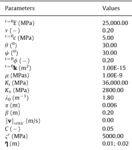
In order to evaluate the proposed procedure in this work and to verify the consequences of using Cosserat continua in the analysis of sand/solids production, the analysis of a hypothetical vertical borehole is carried out. The geometry of the model is represented by a square of size 6.0 m6.0 m, with a circular hole of the 0.20 m diameter located in the center of the square. The initial conditions in terms of stresses considered equal values in both directions, these correspond to 30.0 MPa. An isotropic state of stress was considered as the result of experimental work is available for these conditions and at least qualitative comparisons can be made between numerical and experimental results. The initial pore pressure in rock formation has a magnitude of 22.0 MPa. The mechanical and hydraulic properties necessary for the simulation are presented in Table 1. The simulation process is carried out in stages beginning with the excavation stage. The excavation stage is considered as instantaneous in time. So, there is no sand/solids production in this state. After this stage, a fluid pressure drawdown of 15 MPa is considered, so a mechanical loading of 7.0 MPa is applied at the borehole wall. The simulation time is five days. For the numerical analysis, a finite element mesh composed by 2800 quadrilateral elements and 2880 nodes was used as shown inFig. 1.
a bending modulus (the one relating couple stresses to curva-tures) as shown in[23]. This way, this characteristic length should be related to an assemblage of grains, which would possess a certain bending stiffness as well as introducing a rotational gradient in the medium. In other words, the characteristic length does not represent the dimensions of an individual grain but, necessarily, that of an assemblage of grains. This assemblage
defines a sort of representative elementary volume for the continuum one wishes to model. Experimental evidences show as well that not individual but assemblages of grains detach during sand/solids production[3].
The presentation of results starts with the depiction of the plastic zone in the analyzed model after the excavation stage obtained both with Cosserat continua and with standard con-tinua. As seen inFig. 2, the differences are striking for different values of characteristic length and even more prominent when compared with the results obtained in a standard continuum. After the excavation stage, the plastic zone in the standard continua occupies an area of 0.02689 m2. By assuming a Cosserat continua and a characteristic length of 0.01 m, this value increases to 0.03669 m2, and for a characteristic length of 0.02 m, this increases to 0.04290 m2.Fig. 2shows the deformed geometry with a scaling factor equal to 40 and not damaged zone is represented in blue. One is able to notice that in the case of standard continua, the borehole deformation occurs uniformly and radially, whereas in the Cosserat continua, a localization of deformation occurs around the borehole. This behavior has been found in laboratory tests, as shown in[41]for example. One can associate this mode of deformation with the rotations of the micro-structure, introduced by the anti-symmetric part of shear stress and also to the effect generated by the characteristic length, present in the second set of plastic flow and potential plastic functions (f2 and g2; Eq. (17)), since both are triggered in this analysis. At this point, it should be observed that other authors have demonstrated a capability to numerically represent the behavior observed the laboratory without using specialized con-tinua such as Cosserat concon-tinua. This is, for example, the case of analyses presented in [42]. These authors have analyzed similar cases as the ones presented here by using standard continua procedures. However, in order to achieve localization of deforma-tion as shown here, Detournay[42]needed to add imperfections in the geometry and to impose conditions to the constitutive models adopted, such as the inclusion of softening or non-associated plasticity in the case of hardening. Cosserat continua presents an alternative to standard continua in the sense that it does not need to introduce any of the above for localization. It is however true that Cosserat continua introduces additional para-meters, which would have to be estimated or determined. Although not the main focus of the present work, another favorable aspect for the use of Cosserat continua in the analysis of elastoplastic problems or localization problems has to do with mesh dependency. According, for example to Sharbati and Nagh-dabadi [35]and Iordache and Willam [43], the introduction of Cosserat continua makes localization problems less dependent or even independent from the finite element meshes used. This is particularly important in the case of sand/solids production problems.
Table 1 Dada for example.
Parameters Values
t¼0E(MPa) 25,000.00
n() 0.20
t¼0c(MPa) 5.00
y(0) 30.00
c(0) 30.00
t¼0f() 0.20
t¼0k(m2) 1.00E-15
m(MPas) 1.00E-9
Ks(MPa) 36,000.00
Kp(MPa) 2800.00
l0(m1) 1.80
a(m) 0.006
b(m) 0.20
:v:critic(m/s) 0.00
C() 0.05
Bc(MPa) 5000.00
(m) 0.01; 0.02
Fig. 1.Finite element mesh of borehole geometry.
The characteristics shown in plastic zone after excavation phase had no interference from the sand/solids production process, showing only the importance of considering the Cosserat continua in this type of analysis.
Fig. 3 shows results corresponding to normalized deviatoric plastic strains after the excavation phase, together with the medium deformed geometry using a scale factor of 40. These results show significant differences when considering Cosserat continua as compared to standard continua. In the former, as the characteristic length increases, the effect of localization of plastic deformations is accentuated.
Fig. 4shows the results for the porosity for a time of 41 h. Observe that in standard continua, the porosity presents a more homogeneous pattern than the ones obtained for Cosserat con-tinua. One notes as well, in the case of Cosserat continua, more localized zones of porosity changes, their extension being larger with higher characteristic lengths. In Cosserat continua, porosity
of the order of 87% are encountered, whereas in standard continua, these values are around 72%.
The porosity field obtained after five days after excavation stage shown inFig. 5, also shows different patterns. The results for the standard continua behave uniformly and radially. For the Cosserat continua, the porosity shows a less uniform behavior for a larger characteristic length. According to these results, the model studied tends to stabilize in this configuration, and can be considered that the region with a porosity of 98% was removed from the model.
Considering the zone that produced sand/solids and that after five days was completely removed from the model, one could expect that the pore pressures on the wall of the borehole also show and exhibit a consistent behavior with these results.Fig. 6
shows a plot of pore pressures extending radially away. One is able to notice that the radial variation in pore pressures depends on the type of continua being considered.
Fig. 3.Norm of deviatoric plastic strains and deformed geometry after excavation stage, scaling factor equal to 40, (a) standard continuum, (b) Cosserat continuum with ¼0.01 m and (c) Cosserat continuum with ¼0.02 m.
Fig. 4.Porosity 41 h after excavation stage, (a) standard continua, (b) Cosserat continuum with ¼0.01 m and (c) Cosserat continuum with ¼0.02 m.
Another quantity, which is important in the calculation of sand/solids production according to the production model used in this work, is fluid velocity. Fig. 7 presents the results of the normalized fluid velocity five days after excavation stage. Note the higher values of velocity were obtained when consider-ing the Cosserat continua and a characteristic length of 0.02 m. Perhaps, more significant than the values obtained, is the pattern exhibited by the velocities around the borehole. Velocities present
a uniform and radial behavior in the case of standard continua. In the case of Cosserat continua, the pattern of velocities is rather more heterogeneous and localized. This is most certainly the consequence of strain localization in these models, which as a consequence produce localized changes in porosities and permeabilities.
Fig. 8 shows the behavior of maximum principal effective stresses around the borehole 41 h after excavation stage. The general picture is the same as observed with deformations shown previously. In the case of Cosserat continua, regions of stress concentration appear in a spiral form.
Fig. 9 presents the time evolution of sand/solids production volume being produced. Production volumes appear to be larger for Cosserat continua in comparison to standard continua. Pro-duction rates also appear to be slightly larger for the larger characteristic lengths Cosserat continua.
Figs. 3c and4c present, respectively, localization patterns and porosities for the analyzed case. One is able to notice that the localization zones are located in eight diametrically opposed radial regions. The literature presents[44,45] reports of experi-mental work where patterns such as the ones presented here were found. In other experimental works however, the localiza-tion patterns are restricted to two diametrically opposed radial regions as shown in Fig. 10 of[45].
This localization mode has been referred to as the slit type mode. A study was carried out in order to verify the possibilities of modeling this mode with the Cosserat implementation of the present work. The objective is therefore one of reducing the eight localized regions to two in a natural form, without significant perturbations of the model geometry and material parameters. For that purpose, a characteristic length of 0.02 m was considered. The characteristic lengths of two diametrically opposed finite elements were slightly decreased. This decrease had the effect of activating sooner at these points the second yield surface of Fig. 6.Pore pressure vs. distance.
Fig. 7.Fluid velocity five days after excavation stage, scale in (m/s), (a) standard continua, (b) Cosserat continuum with ¼0.01 m and (c) Cosserat continuum with ¼0.02 m.
Bogdanova-Bontcheva & Lippmann’s model presented in Eq. (17), the one related to couple stresses as mentioned above. However, the evolution of plastic zones and porosities continue to occur around the borehole surface as in the previously analyzed cases. In order to establish a preference zone for the evolution of porosities, a critical velocity :v:critic¼2:00E5m=s was estab-lished (instead of:v:critic¼0 as in the previously analyzed cases). The impact of setting this threshold was to concentrate sand/ solids production in the zone around the points where failure by
couple stresses started. Results for the norm of deviatoric plastic strains (defined inSection 2) and porosity 41 h after excavation stage are presented inFig. 11. One is able to notice the localiza-tion of such quantities in a narrow zone characterizing what is called a slit type mechanism as shown inFig. 10.
Fig. 12 presents sand/solids volume being produced for the analyzed case. One notes that the rate of sand/solids production is approximately constant up to a limit when the rock formation stops producing.
Fig. 10. States of development of slit type mode, from[40].
A further exercise was made in order to understand the formation of the slit mechanism. This time, instead of decreasing the characteristic length of two diametrically opposed elements, this was done only at one element around the borehole. The obtained results are shown inFigs. 13–15. What happened in this
case was that deformations started localizing at this point as shown in Fig. 13, but soon enough and naturally started to localize at the diametrically opposed element as well. It appears therefore that, in order for this mechanism to start, one needs localization at one point around the borehole. The heterogeneous nature of real rocks could provide this condition. The sand/solids production volumes as shown inFig. 15are basically the same as in the previous case shown inFig. 12. It is important to emphasize the relevance of this result. In the rock mechanics literature, it has been proposed that such mechanisms could be attributed to the formation of compaction bands, perpendicular to the in-situ maximum principal stresses. This hypotheses, however, does not apply to the situations analyzed in the present paper, that is, under a hydrostatic state of stresses. The results shown in
Figs. 13 and 14 suggest that the appearance of plastic zones associated to micro-rotations could indeed be the real cause of these mechanisms. To the authors’ knowledge, this suggestion for origin of slit type mechanisms had not yet appeared in the literature.
6. Conclusions
The development and application of finite element method for simulating the process of sand/solids production in boreholes considering the fluid-mechanic coupling and the use of an elasto-plastic Cosserat continuum was presented. In order to model elasto-plastic behavior, the Bognanova-Bontcheva & Lippmann’s constitutive model was used. In order to evaluate the level of importance of Cosserat continua in sand/solids production Fig. 13.(a) Normalized fluid velocity 1.5 h after excavation stage, scale in (m/s). (b) Norm of deviatoric plastic strains 1.5 h after excavation stage.
Fig. 14.(a) Normalized fluid velocity 5 days after excavation stage, scale in (m/s). (b) Porosity 5 days after excavation stage.
prediction studies, different characteristic lengths of the rocks were considered. A hypothetical borehole was used as an example in order to illustrate the implemented procedures. The initial state of stress in the example was isotropic, which allowed qualitative comparisons with experimental work available for these conditions. As shown by other authors, the use of Cosserat continua provides a framework in order to model strain localiza-tion problems. Furthermore and also shown in the literature, sand/solids prediction can be extremely dependent on the failure/ deformational modes happening in the vicinity of boreholes. Obtained results in the present paper showed that this is indeed the case. The paper also presented a successful attempt to model in a natural way slit type failure around the borehole using the implemented models and the consequent prediction of sand/ solids being produced. Work to compare the numerical results using the proposed models with experimental results will be crucial for its validation. The paper showed that the consideration of Cosserat continua can indeed provide an appropriate frame-work for the numerical prediction of sand/solids prediction.
Acknowledgements
The authors thank Petrobras (Petro´leo Brasileiro S/A) for funding the research reported in the present paper and Erling Fjaer for his critical comments and careful review of the paper.
References
[1] Dusseault MB, Santarelli FJ A conceptual model for massive solids production in poorly-consolidated sandstones. Rock at great depth, vol. 2; 1989. p. 789–97.
[2] Fjaer E, Holt RM, Horsrud P, Raaen AM, Risnes R. Petroleum related rock mechanics. Amsterdam: Elsevier; 1992.
[3] Bianco LC. Phenomena of sand production in non-consolidated sandstones. PhD thesis. Penn State University, University Park, Penn; 1999.
[4] Toma P, Harris B, Korpany G, Bohun D, George A. Experimental investigations for reducing the risk of sand inflow in slotted horizontal wells. In: Proceed-ings of the ASME energy source technical conference and exhibition, New Orleans; 1994. p. 1–10.
[5] Geilikman MB, Dusseault MB. Dynamics of wormholes and enhancement of fluid production. In: Proceedings of the 48th annual technical meeting of the petroleum society, Calgary; 1997. p. 8–11.
[6] Unander TE, Papamichos E, Trovoll J, Skjaerstein A. Flow geometry effects on sand production from an oil producing perforation cavity. Int J Rock Mech Min Sci 1997;34:293E1–15.
[7] Morita N Field and laboratory verification of sand production models. In: Proceedings of the technical conference of the society of petroleum engineering, paper SPE 27341; 1994.
[8] Tronvoll J, Skjaerstein A, Papamichos E. Sand production: mechanical failure or hydrodynamic erosion? Int J Rock Mech Min Sci 1997;34:291E1–17. [9] Papamichos E, Tronvoll J, Skjærstein A, Unander TE. Hole stability of Red
Wildmoor sandstone under anisotropic stresses and sand production criter-ion. J Petrol Sci Eng 2010;72:78–92.
[10] Stavropoulou M, Papanastasiou P, Vardoulakis I. Int J Numer Anal Meth Geomech 1998;22:749–69.
[11] Papamichos E, Vardoulakis I. Comput Geotech 2005;32:47–58.
[12] Wang J, Wan RG, Settari A, Walters D. Prediction of volumetric sand production and wellbore stability analysis of a well at different completion schemes. In: Proceedings of the 40th US rock mechanics symposium, Anchorage; 2005.
[13] Liu Y, Wan RG. Computing sand production under foamy oil flow in porous media via least-squares finite elements. Finite Elem Anal Des 2006;42: 592–601.
[14] Detournay C, Tan C, Wu B. Modeling the mechanism and rate of sand production using FLAC. In: Proceedings of the 4th international FLAC symposium on numerical modelling in geomechanics, Minneapolis; 2006.
[15] Detournay C. Numerical modeling of the slit model of cavity evolution associated with sand production. SPE J 2008;14(4):797–804.
[16] Papamichos E. Erosion and multiphase flow in porous media: Application to sand production. Eur J Environ Civ Eng 2010;14:1129–54.
[17] Papamichos E, Vardoulakis I, Tronvoll J, Skjærstein A. Volumetric sand production model and experiment. Int J Numer Anal Meth Geomech 2001;25:789–808.
[18] Papamichos E, Malmanger EMA. sand erosion model for volumetric sand predictions in a North Sea reservoir. SPE Reser Eval Eng 2001;4:44–50. [19] O’Connor RM, Torczynski JR, Preece DS, Klosek JT, Williams JR. Discrete
element modeling of sand production. Int J Rock Mech Min Sci 1997;34: 231E1–15.
[20] Cook BK, Lee MY, DiGiovanni AA, Bronowski DR, Perkins ED, Williams JR. Discrete element modeling applied to laboratory simulation of near-wellbore mechanics. Int J Geomech 2004;4:9–27.
[21] Li L, Papamichos E, Cerasi P. A study of mechanisms of sand production using DEM with fluid flow. In: Cotthem AV, editor. Proceedings of the Eurock 06, Liege; 2006, pp. 241–247.
[22] Cosserat E, Cosserat F. Theorie des Corps Deformables. Paris: A Hermann et Fils; 1909.
[23] Mindlin RD. Stress functions for a Cosserat continuum. Int J Solid Struct 1965;1:265–71.
[24] Bogdanova-Bontcheva N, Lippmann H. Rotationssymmetrisches ebenes Flie\ssen eines granularen Modellmaterials. Acta Mech 1975;21:93–113. [25] Kanatani K. A micro-polar continuum theory for the flow of granular
materials. Int J Eng Sci 1979;17:419–32.
[26] M ¨uhlhaus HB, Vardoulakis I. The thickness of shear bands in granular materials. Ge´otechnique 1987;37:271–83.
[27] Chang CS, Ma L. A micromechanical-based micropolar theory for deformation of granular solids. Int J Solid Struct 1991;28:67–86.
[28] Bardet JP, Vardoulakis I. The asymmetry of stress in granular media. Int J Solid Struct 2001;38:353–67.
[29] Muller AL, Vargas EA, Vaz LE, Gonc-alves CJ. Borehole stability analysis considering spatial variability and poroelastoplasticity. Int J Rock Mech Min Sci 2009;46:90–6.
[30] Muller AL, Vargas EA, Vaz LE, Gonc-alves CJ. Three-dimensional analysis of boreholes considering spatial variability of properties and poroelastoplasti-city. J Petrol Sci Eng 2009;68:268–76.
[31] Lewis RW, Schrefler BA. The finite element method in the deformation and consolidation of porous media. London: Wiley; 1998.
[32] Providas E, Kattis MA. Finite element method in plane Cosserat elasticity. Comp Struct 2002;80:2059–69.
[33] Hongwu Z, Hui W, Guozhen L. Quadrilateral isoparametric finite elements for plane elastic Cosserat bodies. Acta Mech Sinica 2005;21:388–94.
[34] Vardoulakis I, Stavropoulou M, Papanastasiou P. Hydromechanical aspects of the sand production problem. Transp Porous Media 1996;22:225–44. [35] Sharbati E, Naghdabadi R. Computational aspects of the Cosserat finite
element analysis of localization phenomena. Comp Mater Sci 2006;38: 303–15.
[36] Hughes TJR. Unconditionally stable algorithms for nonlinear heat conduction. Comp Meth Appl Mech Eng 1977;10:135–9.
[37] Unterreiner P. Contributiona l e´tude eta la dode´lisation nume´rique des sols cloue´s: application au calcul en deformation des ouvrages de soutenement. Phd these, E´cole Nationale des Ponts et Chausse´es, Paris; 1995.
[38] Lippmann H. Eine Cosserat-Theorie dˆes plastischen Flie\ssen. Acta Mech 1969;8:255–84.
[39] Bendsøe MP, Kikuchi N. Generating optimal topologies in structural design using homogenization method. Comp Meth Appl Mech Eng 1988;71: 197–224.
[40] Bendsøe MP. Optimal shape design as a material distribution problem. Struct Optim 1989;1:193–202.
[41] Van Den Hoek PJ. Prediction of different types of cavity failure using bifurcation theory. In: Proceedings of the 38th US rock mechanics sympo-sium, Washington DC, Paper ARMA 01-0045; 7–10 July 2001.
[42] Detournay C, Wu B, Tan C. Hydro-mechanical modeling of damage around borehole in laboratory experiments. In: Proceedings of the 6th North American rock mechanics symposium, Houston, paper ARMA 04-590; 5–9 June 2004.
[43] Iordache M, Willam K. Localized failure analysis in elastoplastic Cosserat continua. Comput Meth Appl Mech Eng 1998;151:559–86.
[44] Papamichos E. Sand production. Physical and experimental evidence. Geomech. Energy Prod. 2006:803–16.


![Fig. 10. States of development of slit type mode, from [40].](https://thumb-eu.123doks.com/thumbv2/123dok_br/15713951.631199/8.892.169.709.860.1094/fig-states-development-slit-type-mode.webp)

