Corrosion Mechanism Suggested Based on Electrochemical Analysis and SVET for
Uncoated Tinplate and Post Coated With a Hybrid Film
Sandra Raquel Kunsta*, Lilian Vanessa Rossa Beltramib, Rosiana Boniattic, Marcela C. Quevedod,
Alexandre C. Bastosd, Cláudia Trindade Oliveiraa, Mário Ferreirad, Tiago L. Menezese, Célia F. Malfattie
Received: August 29, 2016; Revised: July 10, 2017; Accepted: September 04, 2017
The tinplate, used in the packaging sector and formed from a metal substrate, comprises a steel base which has undergone a surface treatment to produce a thin layer of FeSn2, a tin layer and an oxide tin layer. Currently, packaging using surface treatment is based on the use of chromates because these metals provide an excellent corrosion resistance. Nontoxic alternatives to pre-treatments have been developed in recent years to replace the chromate process. The aim of this work is to analyze the
performance of a new hybrid organic-inorganic ilm obtained from sol-gel consisting of the alkoxide
precursors 3-(Trimethoxysilylpropyl)methacrylate (TMSM) and tetraethoxysilane (TEOS) with the addition of cerium nitrate with the scanning vibrating electrode technique (SVET), and electrochemical and morphological characterizations. Moreover, the evolution of the corrosion of the substrate was evaluated to propose a mechanism of corrosion. The results showed a galvanic coupling between the Sn/SnO2 coat (cathode) and the defects exposed at the ferrous base (anode). The organic-inorganic
hybrid ilm containing a cathodic corrosion inhibitor was able to retard the corrosion of the tinplate.
Keywords: tinplate, corrosion, SVET, hybrid ilms
*e-mail: [email protected]
1. Introduction
Tinplate is a thin low-carbon mild steel sheet, cold reduced, coated on both sides with pure electrolytic tin, linking the strength and formability of the steel with the corrosion resistance and weldability of the tin1,2. Tinplate is largely used in food packaging, being ideally suited for this purpose since it is non-toxic, light strong, and resistant to corrosion3. Tinplate consists of a steel sheet with a typical thickness of 0.1- 0.5 mm coated with a thin layer of electrolytically deposited tin.
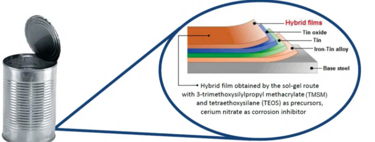
This combination renders the material a non-corrosive characteristic. Further protection was achieved by including an organic top layer. Figure 1 shows the obtained layers from the iron base to the top-coat.
The resulting coating has the following stratiied
structure from bottom to top: a FeSn2 alloy developed from
low-brightening which protects the steel against galvanic
corrosion by oxidant species4.
The thickness of the metal sheet significantly influences the mechanical properties of the material. Along the
years, researchers have been working on modifying the thickness of these materials, aiming, among other things, to reduce costs. Steel represents up to 80% of the cost of packaging and any reduction in thickness of the plate is economics5,6.
Regarding the quality of tinplate, it is worth mentioning the presence of tin oxide on the surface and the passivation layer. Typically, the tinplate has a full or partial coverage of tin oxides (SnOX), which may contain stannous oxide (SnO) or stannic oxide, including its hydrated forms. The presence of excessive amounts of these oxides can change the appearance, the weldability of the metal sheet and the ability to receive organic coatings6,7.
A critical point is observed in the welded region, where the tinplate steel is more exposed due to the partial removal of the tin by the copper wire and its detachment from the surroundings due to the temperature and pressure applied in the welding process. This step removes much of the tin from the tinplate. Moreover, the welding structure, which
has an uneven thickness, becomes diicult to be completely
coated with organic coatings7,8.
aInstituto de Ciências Exatas e Tecnologias - ICET, Universidade Feevale, Novo Hamburgo, RS, Brazil
bPrograma de Pós-Graduação em Engenharia de Processos e Tecnologias - PGEPROTEC,
Universidade de Caxias do Sul - UCS, Caxias do Sul, RS, Brazil
cLaboratório de Corrosão - LACOR, Universidade Federal do Rio Grande do Sul - UFRGS, Porto
Alegre, RS, Brazil
dDepartamento de Engenharia de Materiais e Cerâmica - DEMAC, Universidade de Aveiro, Campus
Santiago, Aveiro, Portugal
eLaboratório de Pesquisa em Corrosão - LAPEC, Universidade Federal do Rio Grande do Sul -
Figure 1. Illustrates system showing the layers obtained from the iron-base to the top coating.
The corrosion rate of a metal protected by an organic coating is related to several aspects, such as the transport of ionic species through the coating, the charge transfer processes in the metal-coating interface, delamination, and changes in the composition of the organic matrix. The performance of a coated metal depends on the polymeric material, porosity, interfacial adhesion, the environment, as well as the integrity of the coating thickness and composition. In a metal-coated polymer system, the formed corrosion products exert tension
in the ilm coating, causing it to break, increasing the number
of defects, with a consequent decrease in the pore resistance of the coating9,10.
Currently, packaging is submitted to a
chromate-based surface treatment, for it ofers excellent corrosion
resistance11,12. Chromates, one of the most eicient types of pretreatments, have been extensively used for a long time. However, the same properties that contribute to a superior corrosion resistance of the thin layers also make them environmentally hazardous. Owing to increasing concerns regarding environmental protection and potential health hazards associated with chromates, their use is being heavily restricted13,14.
Nevertheless, non-toxic pre-treatments have been developed to substitute the chromatization process15,16. For
this reason, the hybrid ilms have been proposed, since
they are associated as part of a same matrix, with organic and inorganic components and combine the most important properties of each constituent17,18. Because they are compatible with overlying organic top-coats, eco-friendly sol-gel derived coatings can also present good adhesion to metallic surfaces via chemical bonding19.
Furthermore, due the numerous application parameters
and curing of hybrid ilms, an enhanced adhesion might be
expected, as metallosiloxane bonds are formed during the condensation reaction. Formation of siloxane chains through the condensation of silanol groups in excess could also yield
a dense network layer acting as an efective barrier against
aggressive species18-20.
The scanning vibrating electrode technique (SVET) has been applied to characterize a great variety of corrosion systems21-24. The visualization of the corrosion progression
is given in terms of the identiication of anodic and cathodic
regions with an estimation of the respective currents and their evolution25.
The objective of this work is to analyze the corrosion mechanism of tinplate with and without a hybrid
organic-inorganic ilm. The hybrid organic-organic-inorganic ilm was
obtained from sol consisting of the alkoxide precursors 3-(Trimethoxysilylpropyl) methacrylate (TMSM) and tetraethoxysilane (TEOS) with the addition of cerium nitrate. The corrosion was evaluated by electrochemical and morphological characterizations.
2. Experimental Procedures
2.1 Surface preparation
Tinplate sheets with dimensions of 20 x 40 mm were obtained from an industrial sheet provided by CSN Company, rinsed with acetone and dried. Then, the plates were degreased by using the neutral detergent from Klintex Insumos, by immersion for 10 min at 70°C, washed and dried. Table 1 shows the composition of the steel sheet before receiving the tin electrodeposition used in this work.
2.2 Elaboration of hybrid ilms
Hydrolysis reactions were conducted with the silane precursors (TEOS) tetraethoxysilane (C8H20SiO4) and (TMSM) 3-(trimethoxysilyl)propylmethacrylate (C10H20SiO5), which were obtained from Aldrich. Reactions were conducted in TEOS/TMSM/alcohol/water solutions in the molar ratio 1/0.125/10.327/7.875 M, respectively, with the addition of 0.01 M cerium nitrate26. After 24 hours of hydrolysis, there
were no signiicant diferences in the pH values, which were
Table 1. Speciication obtained by the provider of the steel sheet before receiving the tin electrodeposition.
Element (%) Cmáx. Mnmáx. Pmáx. Smáx. Simáx. Al Nmáx.
0.06 0.2 0.02 0.02 0.02 0.02-0.06 0.005
Hydrolyzed hybrid solutions were applied by dip coating with an immersion time of 5 minutes and a removal rate of 10 cm.min-1. After the dip coating process the samples were cured at 60 °C for 20 minutes27,28. A description of the samples is presented on Table 2, and the protocol for the sol preparation as well as for the coatings is detailed on the
low chart (Figure 2).
2.3 Experimental techniques
The morphological characterization was carried out by scanning electron microscopy (SEM), performed in a JEOL 6060 device, with an acceleration voltage of 20 kV. The samples were observed in top view and in cross-section to determine the layer thickness.
Sample surface roughness was determined by the
CETR-PRO5003D proilometer. Three areas were analyzed in
each sample to determine the average roughness (Ra). For this kind of analysis, some geometric parameters should
be speciied, as sample size. These values were determined
by the expected roughness as recommended by ISO 4288 standard (ISO 4288:1996, 1996).
The corrosion performance of the coatings was evaluated by open circuit potential (Ecor) monitoring and electrochemical impedance spectroscopy (EIS) measurements
in a 0.05 M NaCl solution. This concentration is suiciently
high to activate corrosion in a relatively short exposure
time, but low enough to enable the efects of various acids
to be determined, and allows the observation of corrosion
inhibitor efects. A three-electrode cell was used to perform
the analysis, with a platinum wire as the counter electrode and SCE as the reference electrode. The working electrode
Table 2. Description of the samples used.
Sample Description
TP-R Tinplate without coating - reference
TP-HF Tinplate coated with a hybrid ilm
Figure 2. Flowchart of the experimental process.
area was 0.626 cm². For the EIS measurements, the systems were previously monitored for up to 96 hours. The amplitude of the EIS perturbation signal was 10 mV, and the frequency ranged from 100 kHz to 10 mHz using a NOVA frequency response analyzer system and an AUTOLAB PGSTAT 30 potentiostat.
The SVET tests were carried out in the Materials and Ceramic Engineering Department at the University of Aveiro, Portugal, using equipment from Microprobes(r) Inc. (USA) and controlled by the ASET ScienceWares software (USA). The electrolyte used in this analysis was 0.05 M NaCl solution. The vibrating electrode was made of platinum-iridium alloy covered with polymer, with the tip uncovered, with a diameter of 10 - 20 mm. The signals considered in this study
were only the ones from the normal ield. The frequency was
162 Hz and the vibration amplitude was twice the diameter
of the tip. The measured potential diferences are converted
into ionic currents after a calibration routine performed with a current source point (microelectrode with a tip ~ 3 mm) conducting a current of 60 nA to 150 mm from the vibration sensor. The calibration is valid for a new solution, since the system was updated with its resistivity. Maps were obtained to a 100 mm plane above the sample surface.
3. Results and Discussion
3.1 Morphological characterization
Figure 3 shows a cross-section analyzed by SEM/ EDS of the tinplate sheets that were received as well as the thickness of the tin layer.
Figure 4 shows SEM micrographs for the hybrid ilm
before the electrochemical tests as well as the thickness of the
layer of the hybrid ilms as determined by the SEM analysis of
Figure 3. Cross section analyzed by SEM / EDS tinplate as received.
Figure 4. Micrographs obtained by SEM (top and cross section)
for the hybrid ilm obtained.
reaction of the ilm due to the precipitation of agglomerates
with a higher concentration of Si due to the addition of TEOS
which provides more silicon groups to this ilm. Besides, a higher densiication of this ilm was observed29, which is due to the covalent bonds of the organic and inorganic precursors. This demonstrates the perfect interaction of TMSM and TEOS
precursors present in the hybrid ilm.
The obtained layer is 0.63 mm (0.11 mm) thick. The layer formation can be associated with the fact that the presence
of TEOS in the ilm increases the number of silanol groups
and, consequently, the inorganic phase amount (siloxane)
increases. This proportion of TEOS was suicient to produce the synergistic efect of the presence of TMSM and TEOS precursors in the hybrid ilm30. Other studies by Si NMR for
these unsupported ilms showed an increase the condensation
degree as a function of TEOS/TMSM ratio increase, obtaining values from 78% to 85%. This increase is manly due to the heterocondensation that occurs between the TEOS and the TMSM which results in siloxane crosslinking reactions and, consequently, in the formation of a dense hybrid network
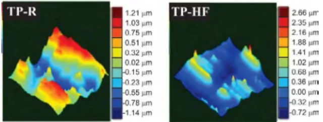
contributing to the thickness and adhesion of the ilms31. Figure 5 shows three-dimensional images obtained
by proilometry and the determined roughness values are
shown in Table 3. The average roughness (Ra) of TP-R and TP-HF samples are very similar. However, the peak to peak roughness of TP-HF sample was higher when compared to sample TP-R. This can be occurred due to irregularities and clusters on the surface of the TP-HF sample.
3.2 Electrochemical characterization
3.2.1 Open circuit potential monitoring
The open circuit potential (OCP) was conducted in an 0.05 M NaCl solution, to check the potential variation with time. The results of the OCP monitoring are shown in Figure
6. It was found that the TP-HF hybrid ilms had their potential
Figure 5. 3D images proilometry obtained by the samples.
Table 3. Samples roughness values , determined by proilometry analysis.
Sample Surface roughness
Ra (µm) Rms (µm) Peak to peak (µm)
TP-R 0.43 ±
0.27 0.51 ± 0.31 2.40 ± 0.83
TP-HF 0.40 ±
0.31 0.50 ± 0.33 3.53 ± 0.37
Figure 6. Open circuit potential curves for the ilmed substrate
(hybrid ilm) and for tinplate without coating.
shifted toward positive values compared with the uncoated tinplate (TR). This behavior is related to the presence of
the barrier layer (hybrid ilm) between the substrate and the
electrolyte, indicating an improved corrosion resistance32. Results reported in the literature show that the hybrid coatings present a higher anti-corrosion resistance than silane ones32.
However, this parameter experiences a small drop between around 1500 at 2200 second of the immersion in an aqueous 0.05 M NaCl solution, indicating that the Si-O-Si is not stable33,34. Consequently, the Si-O-Si reactions
can sufer hydrolysis, forming again the Si-OH hydrophilic
groups so that electrolyte and ions can penetrate and react with the interface35.
3.2.2 Electrochemical impedance spectroscopy
Figure 7 and Figure 8 show, respectively, the Nyquist and Bode diagrams for samples with and without coating, 24 and 96 hours immersion in a 0.05 M NaCl solution.
Figure 7. Nyquist diagrams for tinplate uncoated and tinplate
coated with the hybrid ilms for 24 and 96 hours of immersion in
0.05 M NaCl.
period as compared to the uncoated tinplate. This sample showed resistance values 3 times higher at 24 and 96 hours of immersion when compared to the uncoated substrate (TP-R) (Figure 8). This behavior demonstrates the protective
action of hybrid ilms against corrosion and presented a more
compact, even and probably denser layer. These results are consonance with other researchers35,36, in regards to the fact that the crack-free silane layer improves the barrier properties through its dense reticulation, which forms a less porous layer, thus enhancing the corrosion protection.
However, the resistance of the TP-HF system dropped 6 times from 24 to 96 hours of immersion. This behavior indicates that this system does not withstand long immersion times due to the fact that during the curing process, hydrophobic
siloxane bonds are formed in the ilm network, which hinders
water penetration. However, neither the precursor hydrolysis
nor the cross-linking reactions (polycondensation) during curing are completed. Thus, non-hydrolyzed ester and
hydrophilic OH groups are present in the ilms structures.
These groups, ester and OH, favor the uptake of water, while
the siloxane can be hydrolyzed when the ilms are exposed
to the electrolyte37.
The uncoated tinplate (TP-R) also shows a decrease in resistance of 5 times from 24 to 96 hours of immersion in an 0.05 M NaCl solution. At 24 hours of immersion, the protection is attributed to the tin oxides passivating top layer. However, this oxide does not withstand long immersion times and in 96 hours indicates an acceleration of the interfacial process associated with the tin oxides on the substrate surface38.
Figure 8 shows Bode diagrams obtained for 24 hours of
immersion in the NaCl solution for the hybrid ilm (TP-HF)
and for tin plate substrates. The time constant observed for tin plate in 24 hours was shifted to medium frequencies. This was attributed to the tin oxides passivating top layer 39. The
hybrid ilms showed a time constant in the high frequency
range and a time constant in the medium to low frequency range (Figure 8). This phenomenon in the high frequency range
is associated with the barrier properties of the hybrid ilm.
On the other hand, the phenomenon observed at the medium to low frequency, indicates an acceleration of the interfacial process associated with the tin oxides on the substrate surface.
In 96 hours of immersion (Figure 8) the hybrid ilm
presents one time constant at medium frequency, associated
with the permeation of electrolyte through the hybrid ilm
and reaching the tin oxides indicating an acceleration of the interfacial process associated with the tin oxides on the substrate surface. This could be explained by the non complete curing process and consequently not resistant to longs periods of immersion in the 0.05 M NaCl solution. In 96 hours of immersion the tinplate presented two overlapped time constants, indicating the degradation of the tin oxides. At the end of the experiment, red corrosion products were observed on the electrode surface, indicating that during the
experiment, iron was dissolved and difused to the surface,
thus forming iron oxides.
Tables 4 and 5 show the values of the electric parameters
obtained by the equivalent electric circuit itted to the
electrochemical impedance experimental data for the hybrid
ilm (TP-HF) and the substrate (TP-R), respectively, up to
96 h of immersion by 0.05 M NaCl solution. Errors (%) are shown in parentheses and were lower than 5% in most cases, which demonstrate the suitability of the circuit. These models use a combination of resistances, capacitances and other electrical components, which have a clear physical meaning related to the response of the electrochemical system 37. In this work, we used only one electrical equivalent circuit model for the coated tinplate (TP-HF), which is shown in Figure 7.
Figure 8. Bode diagrams for tinplate uncoated and tinplate coated with the hybrid ilms for (a) 24 and (b) 96 hours of immersion in 0.05 M NaCl.
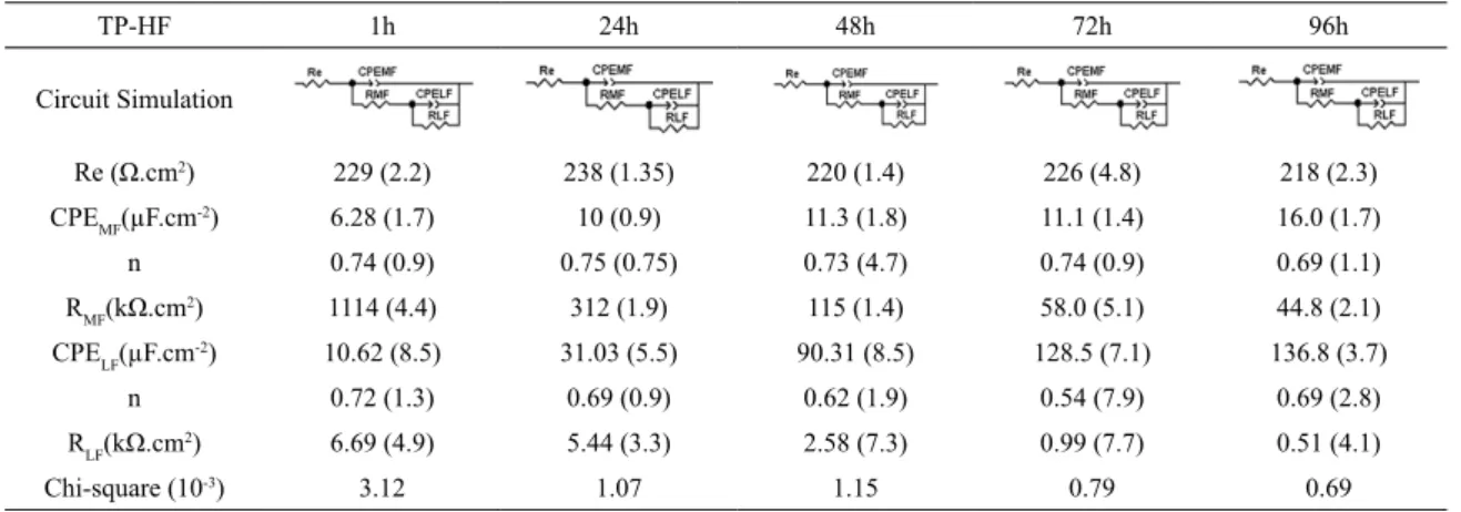
Table 4. Equivalent circuits for the TP-HF sample. The error percentage is in parentheses.
TP-HF 1h 24h 48h 72h 96h
Circuit Simulation
Re (Ω.cm2) 229 (2.2) 238 (1.35) 220 (1.4) 226 (4.8) 218 (2.3)
CPEMF(µF.cm
-2) 6.28 (1.7) 10 (0.9) 11.3 (1.8) 11.1 (1.4) 16.0 (1.7)
n 0.74 (0.9) 0.75 (0.75) 0.73 (4.7) 0.74 (0.9) 0.69 (1.1)
RMF(kΩ.cm2) 1114 (4.4) 312 (1.9) 115 (1.4) 58.0 (5.1) 44.8 (2.1)
CPELF(µF.cm
-2) 10.62 (8.5) 31.03 (5.5) 90.31 (8.5) 128.5 (7.1) 136.8 (3.7)
n 0.72 (1.3) 0.69 (0.9) 0.62 (1.9) 0.54 (7.9) 0.69 (2.8)
RLF(kΩ.cm2) 6.69 (4.9) 5.44 (3.3) 2.58 (7.3) 0.99 (7.7) 0.51 (4.1)
Chi-square (10-3) 3.12 1.07 1.15 0.79 0.69
tinplate and hybrid ilms. A value of n=1 corresponds to a
smooth surface, and therefore the CPE should be substituted
by an ideal capacitor C. A parameter of n=0.5 suggests a response of difusion or porous material, and 0.5<n<1 was
associated to heterogeneous, rough or non-homogeneous current distribution40,41. In the circuit, Re is the electrolyte resistance. The capacitors have been replaced by a constant phase element (CPE).
The corresponding circuit in Table 4 shows the best representation of the samples TP-HF for all immersion times
studied. In these cases, we observed two time constants. A high to medium frequency constant (RMF and CPEMF) shows
a phenomenon associated with the hybrid ilm barrier efect
and also the presence of tin oxides on the metal surface. This behavior was also observed by other authors40,41, indicating
that the hybrid ilms retard the process of corrosion of the
metal substrate. The low frequency time constant (RBF and CPEBF) may be associated with the corrosion of the electrode
produced by permeation through the ilm, which happens
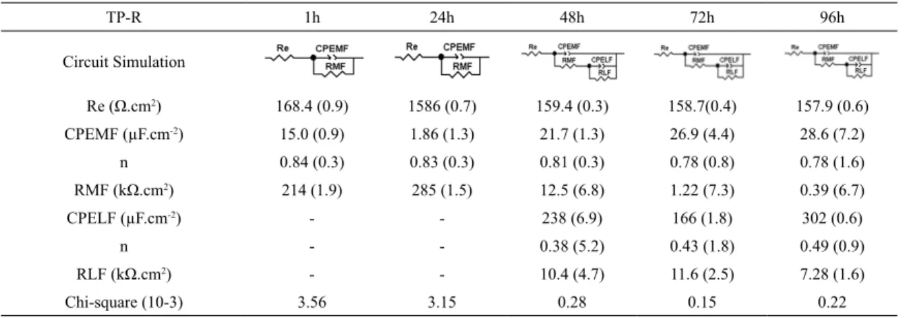
Table 5. Equivalent circuits for the TP-R sample. The error percentage is in parentheses.
TP-R 1h 24h 48h 72h 96h
Circuit Simulation
Re (Ω.cm2) 168.4 (0.9) 1586 (0.7) 159.4 (0.3) 158.7(0.4) 157.9 (0.6)
CPEMF (µF.cm-2) 15.0 (0.9) 1.86 (1.3) 21.7 (1.3) 26.9 (4.4) 28.6 (7.2)
n 0.84 (0.3) 0.83 (0.3) 0.81 (0.3) 0.78 (0.8) 0.78 (1.6)
RMF (kΩ.cm2) 214 (1.9) 285 (1.5) 12.5 (6.8) 1.22 (7.3) 0.39 (6.7)
CPELF (µF.cm-2) - - 238 (6.9) 166 (1.8) 302 (0.6)
n - - 0.38 (5.2) 0.43 (1.8) 0.49 (0.9)
RLF (kΩ.cm2) - - 10.4 (4.7) 11.6 (2.5) 7.28 (1.6)
Chi-square (10-3) 3.56 3.15 0.28 0.15 0.22
hybrid ilm. With an increase in the immersion time, there
is an increase of the pore size. This indicates the transition
period between the electrode behavior of lat and porous ilms, which allows the co-existence of lat and porous ilms42.
For the uncoated tinplate (Table 5), only one time constant is observed for 1 and 24 hours of immersion, and this time constant was attributed to the tin oxides. After 48 hours of immersion, tinplate exhibited two overlapping time constants. A similar result as has been observed by other authors6, which indicates the degradation of the tin oxides and probably the metal corrosion, as a new process governed
by difusion apparently begins as indicated by the low value
of n. This explanation is corroborated by the fact that there is, initially, a high and medium resistance, which declines drastically and that red corrosion products were observed on the electrode surface at the end of the experiment, indicating the formation of iron oxides (Figure 8-a).
Figure 9 shows a representation of the interface between the sample/electrolyte, equivalent to an electric circuit simulation of the data obtained after 96 hours of EIS. The corrosion process involves several simultaneous physical processes and thus, the corresponding equivalent circuit can be composed of various circuit elements. After 96 hours of EIS the equivalent circuit associated with the behavior of both
Figure 9. Physical model of the studied samples, presenting the general equivalent circuit after 96 hours of EIS.
samples (TP-R and TP-HF) is identical. In the TP-R sample the medium frequency constant (RMF and CPEMF) is related to the presence of tin oxide on the metal surface. As to the TP-HF sample, the medium frequency constant (RMF and CPEMF) is
related to the association of the hybrid ilm and the tin oxide.
Tables 4 and 5 show that the RMF after 96 hours of
immersion for the TP-HF sample is 44.8 kΩ.cm2, while for
the TP-R sample is 0.39 kΩ.cm2. This result indicates that
the hybrid ilm associated with the tin oxide (TP-HF sample) has an efective protective action (barrier efect) even after
96 hours of immersion, being far superior to the protection exerted by tin oxide alone (TP-R sample). The painting
may undergo performance issues depending on the speciic
situation to which it was submitted. Therefore, the hybrid
ilm acts as an efective temporary barrier, preventing the
action of corrosive species on the substrate. Thus, temporary minimal protection is guaranteed to the system until the fault in the organic coating is resolved, ensuring product integrity.
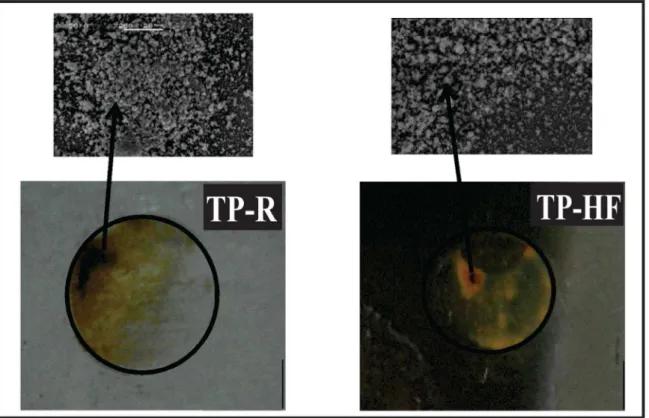
Figure 10 shows the images of the hybrid ilms
(TP-HF) and uncoated tinplate (TP-R) studied after 96 hours of immersion in the electrochemical impedance test. The TP-R samples showed more corrosion products in relation to the
hybrid ilm. This was expected and conirms the results
Figure 10. Images obtained after 96 hours of EIS of the samples.
TP-HF sample also had a good electrochemical performance due to its compact structure, as seen in SEM micrographs in Figure 4. In this system, the permeation of the electrolyte
was prevented by the presence of this ilm on the substrate,
which is in accordance with the results obtained from the open circuit potential (Figure 6).
3.2.3 Immersion test
3.2.3.1 Tinplate corrosion
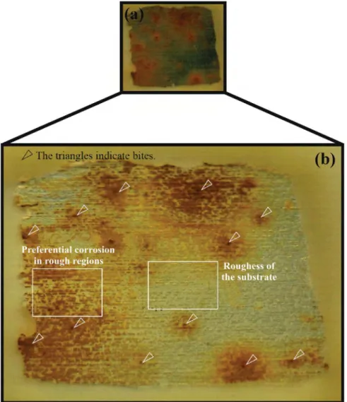
Figure 11 shows the tinplate after 48 hours of immersion in 0.05 M NaCl. In Figure 11-a, preferential points can be easily observed which created corrosion and corrosion products around them. The diluted electrolyte caused very
signiicant attacks on tinplate. However, the tin layer is about 1 μm, and if it was uniform and without defects should
protect iron longer, but it is observed red corrosion of the iron, for possibly tin layer has discontinuities and defects. The immersion assay (Figure 11) shows that part of the tin coating was corroded and the carbon steel was exposed to the electrolyte and so began to corrode1,2,9, releasing iron ions (Equation 1). The dissolved oxygen (Equation 2) react with iron ions, yielding the ferrous hydroxide (Equation 3), which is then oxidized and converted to ferric hydroxide (Fe3O2. H2O) of reddish color (Equations 4 and 5).
(1)
(2)
(3)
(4)
(5)
Figure 11-b shows tinplate roughness and corrosion embossing/roughness of the sample. Therefore, deposits of corrosion can be observed in individual regions that will corrode, which is related to the roughness of the sample. The most rugged regions will corrode preferentially.
By increasing the exposition time, the electrolyte permeated the tinplate substrate through cracks and/or imperfections in the tin and starting the corrosion because of the exposed metal. In the electrolyte NaCl solution (Equation 6), the movement of ions increased the electrical conductivity of the solution and the chloride ions propitiate the beginning of the metal corrosion process.
(6)
Fe
Fe
22
e"
+
+
-O
H O
2
e2
OH
1
2 2
+
2+
"
-
-Q
V
Fe
22
OH
Fe OH
2
"
+
+
-Q
V
Fe OH
2+
OH
"
Fe OH
3
-Q
V
Q
V
Q
V
Fe OH
Fe O H O
H O
2
Q
V
3"
2 3 2+
2
2NaCl
+
H O
2"
Na
+
Cl
+
H O
2-Figure 11. Tinplate after 48 hours immersion in 0.05 M NaCl.
Subsequently, the protective performance of the tin layer was deteriorated and the ions Sn2+ (Equation 7) lowed from the tin.
(7)
3.2.3.2 Corrosion of tinplate coated with hybrid ilm
Further analysis of the immersion test was proposed to verify the mechanism of corrosion of the tinplate coated
with hybrid ilm (TP-HF). The sample with hybrid ilm
(PD-HF) underwent the same form of corrosive attack observed on the uncoated sample (TP-R), yet the process is
slower. This diference was observed in the electrochemical
impedance tests.
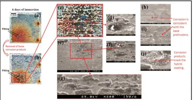
Figure 12 shows a selection of micrographs that illustrates the behavior of the TP-HF sample after 6 days of immersion in 0.05 M NaCl solution. As Figure 11-a depicts, there is the formation of corrosion products isolated on the surface of the sample. This indicates that the corrosion product was
Sn
Sn
22
e
"
+
+
-generated at points and/or individual regions that will corrode preferentially, related to the roughness of the tinplate substrate. Figure 12-b shows that corrosion products accumulate
under the hybrid ilm, i.e., corrosion starts due to failure or
discontinuities in the coating and begins to corrode, then it
spreads and accumulates underneath the hybrid ilm until
reaching a moment when the quantity of corrosion products is great enough to break the sol-gel coating. The products begin to appear on the top of the coating (Figure 12-c) where there is sol-gel broken up by the corrosion products.
The most rugged regions will corrode preferentially, and these defects were observed in the uncoated tinplate (Figure 11-b). This form of corrosion also happens with the
application of the hybrid ilm. The red color arises because
Figure 12. Selection of images obtained from the TP-HF sample after 6 days immersion in 0.05 M NaCl.
Figure 13. Corrosion mechanism for the tinplate coated with hybrid
ilm in the electrolyte NaCl solution.
Figure 12-e shows, in more detail, the corrosion formed on the surface of the TP-HF sample. A detailed analysis of the SEM image of the sample shows that corrosion occurs
at speciic points (Figures 12-f-g). Moreover, it is noted
that the corrosion products appear mainly in the hybrid
ilm irregularities, which are shaped irregularities and/
or the roughness of the tinplate. Those areas in which the
corrosion starts preferentially, are defects of the ilm and
the tin layer reaching the iron, producing a reddish color in the corrosion product.
Figure 12-h indicates that corrosion occurs by irregularities,
where there is a degradation of the hybrid ilm forming
clusters and under these clusters there are corrosion products resulting from the defects in the substrate. Furthermore, the microscopic image showed abundant dark corrosion products indicating the degradation of the tin oxides.
Figure 13 shows the corrosion mechanism for tinplate
coated with hybrid ilm in the NaCl electrolyte solution. In
this scheme, the spot corrosion was omitted, that is, pitting occurred. In this case, another form of corrosion will be highlighted.
3.3 Scanning vibrating electrode test
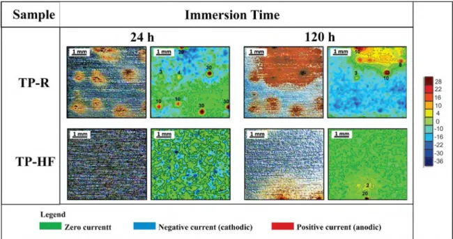
Figure 14 shows the images of the surface and SVET maps of the uncoated tinplate (TP-R). The green color corresponds to zero current, the blue color corresponds to negative currents (cathode) and red color is related to the positive current (anode).
The tinplate corrosion (TP-R) was detected from the beginning of the immersion, with localized anodic and cathodic spots being the remaining area. In 24 hours of immersion 8 pits were observed in an area of 16 mm2. After 120 hours, some original pits were gone and the corrosion migrated to other regions of the sample. The anodic activity was
signiicantly located in a region with abundant accumulation
of corrosion products. The rest of the surface presented
Figure 14. SVET micrographs of the samples, after 24 h and 120 h of immersion in 0.05 M NaCl.
pits. This may be due to the deposition of corrosion products from iron, which can increase the cathodic activity through an increased surface area site or improving the catalytic oxygen reduction reaction.
The hybrid ilm sample (TP-HF) showed an eicient protective efect, as corrosion was detected only on the
second day of immersion with a small pit. After 120 hours of immersion, this sample showed only two small points of corrosion, and only one of them was active.
4. Conclusions
The results showed a galvanic coupling between the Sn/SnO2 coat (cathode) and the ferrous base exposed at the
defects (anode). The organic-inorganic hybrid ilm was able
to retard the corrosion of the tinplate.
Furthermore, the corrosion products of the hybrid ilms
showed that the corrosion occurs at the irregularities arising from defects in the substrate. First, corrosion occurs in the
areas of protruding roughness under the irst hybrid ilm but then corrosion products break the ilm and are visible
directly. Similarly to the tinplate without coating, but at a higher speed in the beginning, there are corrosion deposits that are, in fact, isolated regions that will corrode, related to the roughness of the sample. Thus, the most rugged regions will corrode preferentially.
The results obtained by the SVET showed that the TP-HF sample had a good performance when immersed in the NaCl solution. The corrosion was detected only at the second day of immersion with a small pit. After 120 hours this system displayed just two small points of corrosion, indicating the
efective barrier efect of the ilm.
Based on the results, we found that the hybrid ilm that was developed on a TMSM and TEOS base is efective as
a protective coating when applied on tinplate. The presence
of the hybrid ilm retards the action of corrosion and ensures
the integrity of the tinplate for longer when exposed to aggressive media.
5. Acknowledgments
The authors would like to express their gratitude for the
inancial support of CAPES (a Brazilian Governmental agency
for the development of human resources) and CNPq (the
Brazilian National Council for Scientiic and Technological
Development).
6. References
1. Xia D, Wang J, Song S, Zhong B, Han Z. The Corrosion Behavior of Lacquered Tinplate in Functional Beverage.
Advanced Materials Research. 2011;233-235:1747-1751.
2. Zumelzu E, Cabezas C. Observations on the inluence of
microstructure on electrolytic tinplate corrosion. Materials
Characterization. 1995;34(2):143-148.
3. Chen S, Xie L, Xue F. X-ray photoelectron spectroscopy investigation of commercial passivated tinplate surface layer.
Applied Surface Science. 2013;276:454-457.
4. Álvarez D, Collazo A, Pérez C. The use of sol-gel ilm as
pre-treatment for tinplate used in the canning industry. Progress in Organic Coatings. 2013;76(12):1819-1826.
5. Álvarez D, Collazo A, Nóvoa XR, Pérez C. The anticorrosive
properties of sol-gel ilms doped with hydrotalcite nanoparticles
Society of China. 2012;22(3):717-724.
8. Martins JI. Corrosion problems in tinplate cans for storing contact glues for shoes. Engineering Failure Analysis. 2012;26:258-265.
9. Carbonini P, Monetta T, Nicodemo L, Mastronardi P, Scatteia B, Belluci F. Electrochemical characterization of multilayer organic coatings. Progress in Organic Coatings. 1996;29(1-4):13-20.
10. Murillo-Gutiérrez NV, Ansart F, Bonino JP, Kunst SR, Malfatti CF. Architectural optimization of an epoxy-based hybrid sol-gel coating for the corrosion protection of a cast Elektron21 magnesium alloy. Applied Surface Science. 2014;309:62-73.
11. Rosalbino F, Scavino G, Mortarino G, Angelini E, Lunazzi G. EIS study on the corrosion performance of a Cr(III)-based conversion coating on zinc galvanized steel for the automotive industry. Journal of Solid State Electrochemistry. 2010;15(4):703-709.
12. Huang X, Li N, Wang H, Sun H, Sun S, Zheng J. Electrodeposited
cerium ilm as chromate replacement for tinplate. Thin Solid Films. 2008;516(6):1037-1043.
13. Brusciotti F, Batan A, De Graeve I, Wenkin M, Biessemans M, Willem R, et al. Characterization of thin water-based silane pre-treatments on aluminium with the incorporation of nano-dispersed CeO2 particles. Surface and Coatings Technology.
2010;205(2):603-613.
14. Shi H, Liu F, Han E. Corrosion behaviour of sol-gel coatings doped with cerium salts on 2024-T3 aluminum alloy. Materials
Chemistry and Physics. 2010;124(1):291-297.
15. Nincević Grassino A, Grabarić Z, Pezzani A, Fasanaro G, Lo Voi A. Inluence of essential onion oil on tin and chromium
dissolution from tinplate. Food and Chemical Toxicology. 2009;47(7):1556-1561.
16. Hu H, Li N, Cheng J, Chen L. Corrosion behavior of chromium-free dacromet coating in seawater. Journal of Alloys and
Compounds. 2009;472(1-2):219-224.
17. Palomino LM, Suegama PH, Aoki IV, Montemor MF, de
Melo HG. Electrochemical study of modiied non-functional
bis-silane layers on Al alloy 2024-T3. Corrosion Science.
2008;50(5):1258-1266.
18. Naderi R, Fedel M, Delorian F, Poelman M, Olivier M. Synergistic efect of clay nanoparticles and cerium component
on the corrosion behavior of eco-friendly silane sol-gel layer applied on pure aluminum. Surface and Coatings Technology.
2013;224:93-100.
19. Kunst SR, Beltrami LVR, Cardoso HRP, Vega MRO, Baldin
EKK, Menezes TL, et al. Efect of curing temperature and architectural (monolayer and bilayer) of hybrid ilms modiied
with polyethylene glycol for the corrosion protection on tinplate.
Materials Research. 2014;17(4):1071-1081.
Corrosion Science. 1988;28(6):547-558.
22. Aldykiewicz AJ Jr., Isaacs HS. Dissolution characteristics of duplex stainless steels in acidic environments. Corrosion
Science. 1998;40(10):1627-1646.
23. Ogle K, Baudu L, Garrigues T, Philippe X. Localized Electrochemical Methods Applied to Cut Edge Corrosion. Journal of the Electrochemical Society. 2000;147(10):3654-3660.
24. Vuillemin B, Philippe X, Oltra R, Vignal V, Coudreuse L, Dufour LC, et al. SVET, AFM and AES study of pitting corrosion initiated on MnS inclusions by microinjection. Corrosion
Science. 2003;45(6):1143-1159.
25. Bastos AC, Karavai OV, Zheludkevich ML, Yasakau KA, Ferreira MGS. Localised Measurements of pH and Dissolved Oxygen as Complements to SVET in the Investigation of Corrosion at Defects in Coated Aluminum Alloy. Electroanalysis.
2010;22(17-18):2009-2016.
26. Malfatti CF, Menezes TL, Radtke C, Esteban J, Ansart F,
Bonino JP. The inluence of cerium ion concentrations on the characteristics of hybrid ilms obtained on AA2024-T3 aluminum
alloy. Materials and Corrosion. 2012;63(9):819-827.
27. Kunst SR, Cardoso HRP, Ortega MR, Beltrami LVR, Menezes
TL, Malfatti CF. The efects of curing temperature on bilayer and monolayer hybrid ilms: mechanical and electrochemical
properties. Journal of Applied Electrochemistry. 2014;44(7):759-771.
28. Kunst SR, Beltrami LVR, Cardoso HRP, Menezes TL, Malfatti
CF. UV Curing Paint on Hybrid Films Modiied with Plasticizer Diisodecyl Adipate Applied on Tinplate: The Efects of Curing
Temperature and the Double Layer. Industrial and Engineering Chemistry Research. 2014;53(49):19216-19227.
29. Marcolin P, Beltrami LVR, Souza JM, Boniatti R, Menezes TL, Correa CA, Quevedo MC, Bastos AC, Ferreira MGS, Oliveira CT, Moura ABD, Fuhr LT, Schneider EL, Malfatti CF, Kunst
SR. Inluence of the Polyethyleneglycol Plasticizer on the on
the Mechanical and Electrochemical Properties of Siloxane Hybrid Films Applied on Tinplate. International Journal of Electrochemical Science. 2017; 12:943-958.
30. Wang M, He D, Xie H, Fu L, Yu Y, Zhang Q. Characterization
of bis-[triethoxysilylpropyl] tetrasulide layers on aluminum
based on water-based silanization solution. Thin Solid Films. 2012;520(17):5610-5615.
31. Sakai RT, Cruz FMDL, Melo HG, Benedetti AV, Santilli CV, Suegama PH. Electrochemical study of TEOS, TEOS/MPTS, MPTS/MMA
and TEOS/MPTS/MMA ilms on tin coated steel in 3.5% NaCl
solution. Progress in Organic Coatings. 2012;74(2):288-301.
32. Sarmento VHV, Schiavetto MG, Hammer P, Benedetti AV, Fugivara CS, Suegama PH, et al. Corrosion protection of stainless steel by polysiloxane hybrid coatings prepared using the sol-gel process. Surface and Coatings Technology.
33. Behzadnasab M, Mirabedini SM, Kabiri K, Jamali S. Corrosion performance of epoxy coatings containing silane treated ZrO2 nanoparticles on mild steel in 3.5% NaCl solution. Corrosion
Science. 2011;53(1):89-98.
34. van Ooij WJ, Zhu D, Stacy M, Seth A, Mugada T, Gandhi J, et al. Corrosion Protection Properties of Organofunctional Silanes-An Overview. Tsinghua Science & Technology. 2005;10(6):639-664.
35. van Ooij WJ, Zhu D. Electrochemical Impedance Spectroscopy of
Bis-[Triethoxysilypropyl]Tetrasulide on Al 2024-T3 Substrates.
Corrosion. 2001;57(5):413-427.
36. Zhu D. Corrosion Protection of Metals by Silane Surface
Treatment. [Thesis]. Cincinnati: University of Cincinnati; 2005. 37. Suegama PH, Sarmento VHV, Montemor MF, Benedetti AV,
Melo HG, Aoki IV, et al. Efect of cerium (IV) ions on the
anticorrosion properties of siloxane-poly(methyl methacrylate)
based ilm applied on tin coated steel. Electrochimica Acta.
2010;55(18):5100-5109.
38. Souza MEP, Ariza E, Ballester M, Yoshida IVP, Rocha LA, Freire CMA. Characterization of organic-inorganic hybrid coatings for corrosion protection of galvanized steel and electroplated ZnFe steel. Materials Research. 2006;9(1):59-64.
39. Jayaraj B, Desai VH, Lee CK, Sohn YH. Electrochemical impedance spectroscopy of porous ZrO2-8 wt.% Y2O3 and thermally grown oxide on nickel aluminide. Materials Science
and Engineering: A. 2004;372(1-2):278-286.
40. Conde A, Damborenea JJ. Electrochemical impedance spectroscopy for studying the degradation of enamel coatings.
Corrosion Science. 2002;44(7):1555-1567.
41. Bajat JB, Milošev I, Jovanović Ž, Jančić-Heinemann RM, Dimitrijević M, Mišković-Stanković VB. Corrosion protection
of aluminium pretreated by vinyltriethoxysilane in sodium chloride solution. Corrosion Science. 2010;52(3):1060-1069.
42. Varma PCR, Colreavy J, Cassidy J, Oubaha M, McDonagh
C, Dufy B. Corrosion protection of AA 2024-T3 aluminium