ISSN 1517-7076 artigo e11858, 2017
Autor Responsável: Marcio Ferreira Hupalo Data de envio: 12/08/2016 Data de aceite: 20/12/2016
10.1590/S1517-707620170003.0192
Influence of casting heterogeneities
on microstructure and mechanical
properties of austempered
ductile iron (ADI)
Ludiere Lucas Toldo Boneti, Marcio Ferreira Hupalo, Selauco Vurobi Junior, Adriano Murilo Rosário.
Universidade Estadual de Ponta Grossa, Departamento de Engenharia de Materiais, CIPP, 84030-900, Ponta Grossa, PR e-mail: [email protected]
e-mail: [email protected]; [email protected]; [email protected]
ABSTRACT
An investigation was carried out to examine the influence of as-cast heterogeneities on the resulting micro-structure and mechanical properties of an austempered ductile cast iron (ADI). A commercial hypereutectic ductile iron alloy with 3.59% C, 2.68% Si, 0.24% Mn and 0.46% Cu (in wt. %) was produced in a coreless induction furnace. The specimens were obtained by casting the alloy into Y-block molds. The austempering heat treatments consisted of pre-heating at 500°C, followed by austenitizing step at 900°C and 930°C during 60 minutes. Austempering was carried out in molten metal baths at temperatures of 300°C and 370°C for 30 minutes. Microstructural characterization was carried out by light optical microscopy (LOM) with image analysis, scanning electron microscopy (SEM-FEG) and X-ray diffraction with Rietveld refinement. The me-chanical properties were evaluated by tensile and Vickers hardness tests. The results of this investigation in-dicate that as-cast heterogeneities have a detrimental effect on the transformed microstructure and mechani-cal properties of ADI. During austempering, non uniform distribution of graphite nodules and segregation of alloying elements at cell boundaries resulted in transformation gradients throughout the metallic matrix. In-tercellular regions displayed inhomogeneous microstructures containing eutectic carbides and martensite. Yield strength, tensile strength and hardness decrease for increasing austempering temperature. Fracture sur-faces showed a rapid transition from ductile to cleavage mode at intercellular regions, containing solidifica-tion carbides.
Keywords: Austempered ductile iron (ADI), casting heterogeneities, bainitic ferrite, retained austenite, me-chanical properties.
1. INTRODUCTION
Austempered Ductile cast Iron (ADI) continues to attract considerable interest because of its remarkable combination of properties such as high strength and ductility, high fracture toughness and good wear re-sistance. ADI has been considered an economical substitute for forged steels in many structural components due to its lower fabrication cost and higher specific strength. Moreover, the strength-to-weight ratio of the material is among the highest and its relative cost per unit of yield strength among the lowest of all engineer-ing materials, includengineer-ing aluminum. Typical examples of application include pieces for earthmovengineer-ing machin-ery and mining, agricultural equipment, transmission gears, crankshafts and suspension parts for vehicles [1,2,3,4,5].
obtained within the PW. A more detailed description of the austempering reaction is available in other refer-ences [3,7,8,9].
Mechanical properties can be controlled in ADI by changing the heat treatment conditions and hence, the microstructure. When discussing the microstructure, it is necessary to distinguish between residual aus-tenite, which exists at the austempering temperature () and retained austenite (R), which remains untrans-formed at room temperature. A mixture of bainitic ferrite (αB) and retained austenite (R), with graphite nod-ules homogeneously dispersed in it, is the most desirable combination of phases in ADI [1,3]. This micro-structure is often termed as “ausferrite” rather than bainite as in austempered steels where the microstructure consists of ferrite, retained austenite and carbides [2,5]. However, undesirable phases such as martensite and eutectic carbides may also be present in the microstructure of ADI. The response of a ductile iron to austem-pering depends on the complex interaction between different factors such as alloy chemistry, segregation, austenitizing temperature, austempering time and temperature [5,10]. The austenitizing temperature deter-mines the initial carbon content of the austenite matrix prior to transformation, and the austempering temper-ature determines the carbon content of the stabilized austenite upon transformation. The ntemper-ature of the bainitic microstructure also depends on the austempering temperature and time. Higher austempering temperatures, e.g. 370°C, produce a coarser ferrite but in a lower volume fraction. This is accompanied by a reduction in yield strength and hardness. Lower austempering temperatures, e.g. 280°C, result in finer and greater volume fractions of ferrite, and higher yield strength. So, the combination of austenitizing and austempering tempera-ture determines the refinement degree and amount of stabilized austenite present in the transformed structempera-ture, which in turn controls properties [3,5,9].
Because of the combination of high strength and high toughness that can be achieved in an austem-pered matrix it is expected that degradation in properties due to casting quality such as poor nodularity, low nodule count, undissolved carbides or porosity will be more severe for ADI than for ductile irons with other matrix structures [4,5,11]. Nodule count and nodularity are the most sensitive indicators of ductile iron quali-ty. High nodule counts tend to promote nodularity and minimize segregation and carbide formation in the intercellular regions. There are many variables affecting the nodule count, including charge materials, melt-ing practice, inoculation and nodulization treatments, pourmelt-ing temperature and section size [12]. Most of the literature reports the processing of ADI with regard to aspects associated to the influence of heat treatment parameters on its microstructure and mechanical properties. However, the effects of ductile iron quality on the microstructure and properties of ADI have received little attention.
The primary objective of this study was to investigate the influence of as-cast structure heterogeneities on microstructure and mechanical properties of a commercial ductile cast iron submitted to austempering heat treatments. The secondary objective was to evaluate the effect of austenitizing and austempering tem-peratures on microstructure and properties of ADI. The microstructures of as-cast and austempered samples were characterized by light optical microscopy (LOM), scanning electron microscopy (SEM-FEG) and X-ray diffraction (XRD). Mechanical properties were evaluated by tensile and Vickers hardness tests. The fracture surfaces of tensile specimens were also investigated using SEM. The main results of this characterization will be presented and discussed.
2. MATERIALS AND METHODS
A commercial hypereutectic ductile cast iron alloy, with the chemical composition given in Table 1, was pro-duced in a 2,000 kg capacity coreless induction furnace. Steel scrap, low phosphorous pig iron and ductile iron return were used as raw materials. The nodulization step was carried out using the sandwich method and 1.4% of FeSiMg7. The cast was then inoculated with 0.6% of FeSi75 and poured into standard 25.4 mm Y-blocks.
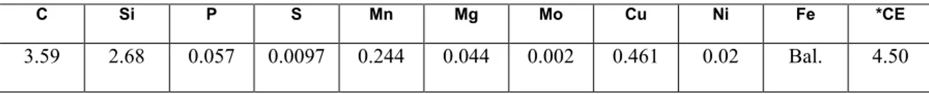
Table 1: Chemical composition of ductile cast iron used in the present study (in wt. %)
*Carbon equivalent, CE = %C + 0.333 (%Si + %P), [12].
Two types of specimens were cut from the bottom half of Y-blocks: a rectangular specimen (15x6x6 mm) for purposes of microstructural characterization and cylindrical specimens with 12 mm diameter used to produce mechanical test samples according to standard DIN 50125. Metallographic and mechanical test
spec-C Si P S Mn Mg Mo Cu Ni Fe *CE
imens were pre-heated at 500ºC for 15 minutes and then austenitized at 900°C and 930°C for 60 minutes pri-or to isothermal heat treatment (austempering) at 300°C and 370°C fpri-or 90 minutes. Austenitization step was performed in a tubular furnace with capacity to 1200°C. Austempering heat treatment was performed in an isothermal metallic bath consisting of a 60%Sn-40%Pb alloy, which has a melting point below 200°C. A K-type thermocouple was inserted into the bath to control the temperature throughout heat treatment. After the isothermal heat treatment the specimens were air-cooled to room temperature.
The metallographic preparation followed standard techniques. Metallographic etching was performed employing 2% Nital and LePera etchant, which allows the differentiation of bainite from martensite. Micro-structural characterization was performed by light optical microscopy (LOM), scanning electron microscopy (SEM-FEG, Tescan-Mira 3) and X-ray diffraction (XRD, Shimadzu-XRD 6000). Nodularity and nodule count values were measured by Image-Pro Plus software. The XRD spectrum of each sample was obtained in the 2 range from 40° to 110° by using the graphite monochromated Cu-K radiation, at a rate of 0.02°/min and a delay time of 6 s. The profiles were analyzed using GSAS [13] software to obtain the peak positions and the integrated intensities of {111}, {200}, {220} and {311} planes of austenite and {110}, {200}, {211} and {220} planes of ferrite. The volume fractions of ferrite (αB) and retained austenite (R) were determined by the direct comparison method using the integrated intensities of the above planes. Tensile tests were con-ducted in agreement with the ASTM E8-M standard using a universal testing machine (Emic DL 30kN). The values of all the properties reported are the average of testing three specimens. Vickers hardness tests were performed in austempered samples using a Leica VMHT MOT indenter with a load of 500 gf and 15 meas-urements per sample.
3. RESULTS AND DISCUSSION
3.1 As-cast material
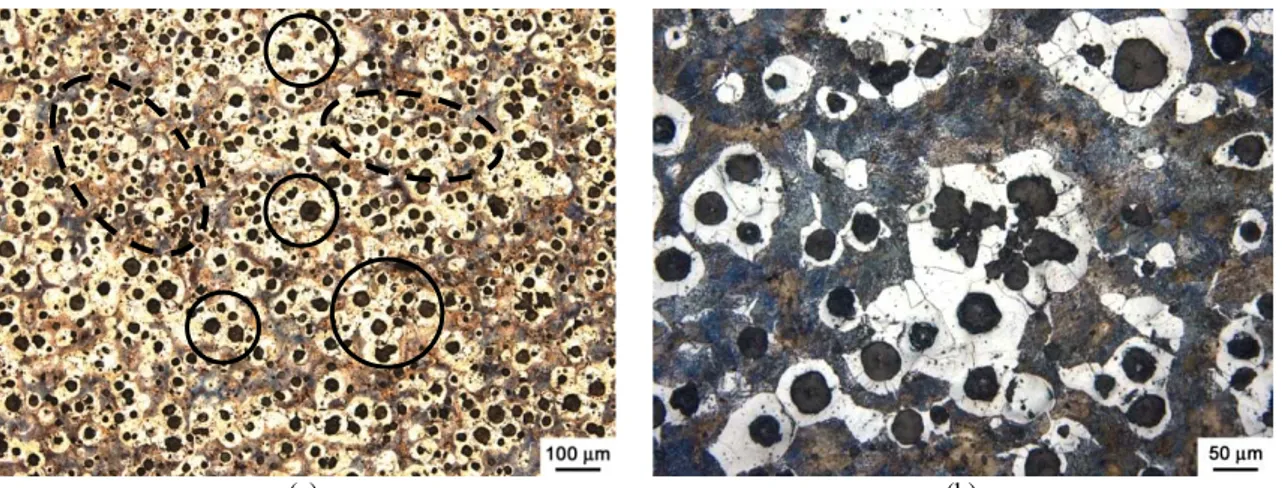
Figure 1 shows optical micrographs of the as-cast ductile iron alloy. The microstructure was composed of 14% graphite, 52% ferrite and 34% perlite. The measured nodule counting was 197 nodules per mm2 with 85% nodularity. As shown in Figure 1a the graphite nodules in the as-cast material were not uniform in size and distribution. The nodule size varied between 10 and 70 m. Figure 1 also reveals the presence of primary graphite nodules (marked in solid black line circles) surrounded by clusters of smaller nodules (highlighted in dashed black line ellipses). This heterogeneous distribution can be related to graphite floatation and/or ineffi-cient inoculation. Graphite floatation is caused by excessive growth of some nodules, which incorporate car-bon directly from the liquid. Due to the lower density of graphite these nodules tend to float and cluster. This phenomenon is observed during the solidification of thick sections or in the presence of slow cooling rates [5,12]. It is worthwhile mentioning the thick sections of Y-blocks used in this work, of 25.4 mm.
(a) (b)
Figure 1:Light optical micrographs of as-cast material: a) heterogeneous distribution of graphite nodules showing prima-ry graphites (solid black line circles) and clustered nodules (dashed black line ellipses); b) detail of microstructure con-sisting of ferrite and perlite. Etching with 2% Nital.
Fig-ure 1a) have been formed very early during the solidification process [5,8,12]. It is generally accepted that one should produce castings with consistent graphite characteristics and then control the mechanical proper-ties by the microstructure of the matrix. In the as-cast condition, the properproper-ties of a defect-free unalloyed casting will be governed by the ferrite/perlite ratio [3,5,8].
During cooling, as the cast iron alloy is hypereutectic (CE = 4.50, see Table 1) graphite will be the first phase to form. Thus, the first regions to solidify contain the graphite nodules and the last regions to so-lidify are those remote from the nodules. As undercooling progresses below the eutectic temperature, graph-ite and austengraph-ite grow simultaneously as a divorced eutectic, with the austengraph-ite forming in shells surrounding the graphite. Growth of the graphite proceeds by diffusion of carbon through the austenite. As cooling pro-gresses, solute atoms partition between the solid and liquid, so that the composition of the solid changes and a chemical segregation profile is produced [12]. This segregation profile leads to the formation of ferrite close to the nodule and perlite remote from the nodule; this is termed a “bull's-eye” microstructure and can be seen in Figure 1b. The presence of segregation in the as-cast matrix leads to inhomogeneity in volume frac-tions of the various phases which make up the microstructure of ADI, as will be discussed in the results of characterization of austempered samples.
3.2 Characterization of austempered samples
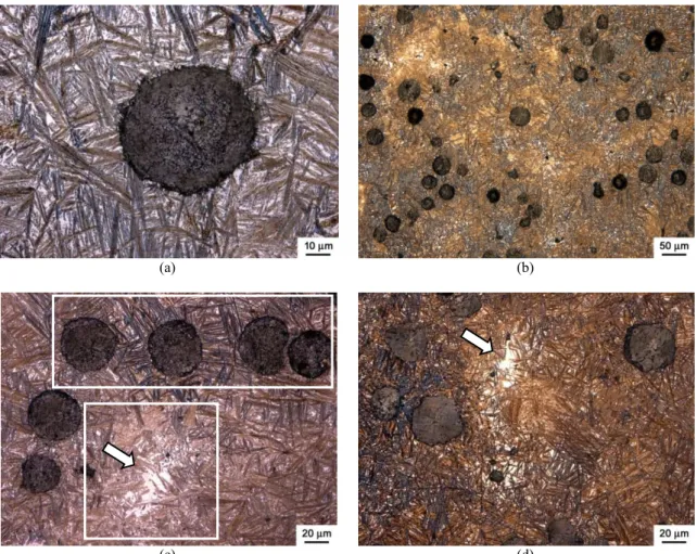
Microstructures of the austempered samples were examined by optical and scanning electron microscopy after etching with 2% Nital and LePera etchant. Some representative microstructures are presented in Figures 2-4. As shown in Figure 2a, the austempered microstructure shows a matrix consisting of a two-phase mix-ture of a dark etching bainitic ferrite which is needle shaped and the bright etching austenite with graphite nodules dispersed in it.
(a) (b)
(c) (d)
Figure 2: Set of light optical micrographs for a sample austenitized at 900°C and austempered at 370°C showing: a) typi-cal microstructure of ADI; b) segregation at intercellular regions (lighter brown areas); c) and d) transformation gradients after austempering and eutectic carbides. Etching with 2% Nital.
“sheaves”; in fact consist of groups of sheaves which form with specific orientation relationships to each ot h-er, these groups have been referred to as “bundles”. The sheaves themselves are composed of sub-units of ferrite [14,15,16]. Initially ferrite nucleates on the graphite/austenite interface or at austenite grain boundaries and then grows, by the sympathetic nucleation of further plates, into the austenite producing the characteristic sheaf structure. During this transformation carbon is rejected by the growing bainitic ferrite and diffuses into the austenite or, at lower austempering temperatures, forms carbides with the bainitic ferrite, the degree to which these carbides can form decreases as Si content increases [16,17].
The effect of heterogeneous distribution of graphite nodules on ADI microstructure is clearly demon-strated in Figures 2b-d. These micrographs were taken from a sample austenitized at 900°C and austempered at 370°C. They reveal the presence of transformation gradients between the intercellular regions (highlighted in white square at Figure 2c) and regions richer in graphite nodules (marked in white rectangle at Figure 2c). Alloying elements like molybdenum and manganese segregate strongly into the intercellular region stimulat-ing carbide formation and thus delaystimulat-ing the austemperstimulat-ing reactions in these areas [2,8,11]. The precipitates which form during the solidification of ductile iron castings can easily be identified by the white arrows in Figures 2c–d (after austempering), detached from the light background of retained austenite. It can be seen that these regions display heterogeneous microstructures, in contrast with higher homogeneity observed near the graphite nodules. It is suggested that, if these particles are carbides, they might begin to dissolve during austenitization increasing the local carbon content and delaying the formation of bainite, producing a “halo” effect around the eutectic carbides [3,7,17].
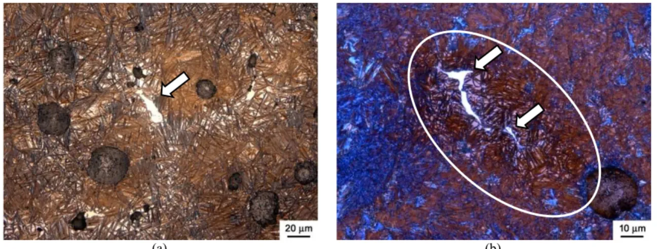
In castings solidifying at an intermediate or slow rate, manganese segregates at cell boundaries caus-ing the precipitation of intercellular complex Fe-Mn carbides [1,12], as illustrated in the micrographs of Fig-ure 3 (marked in white ellipse), obtained for a sample austenitized at 900°C and austempered at 300°C. These manganese stabilized carbides usually remain as a highly brittle phase in the structure after the austempering treatment. Segregation of manganese at cell boundaries also results in a heterogeneous hardenability of the matrix by increasing the stability of the intercellular austenite.
(a) (b)
Figure 3: Light optical micrographs of a sample austenitized at 900°C and austempered at 300°C showing the presence of eutectic carbides at intercellular regions: a) etching with 2% Nital; b) etching with LePera reagent.
Segregated regions may either transform to martensite after cooling from the austempering tempera-ture [2,5,7]. The micrograph of Figure 3b, obtained after etching with LePera reagent, shows a good example of coexistence of bainitic ferrite (dark brown needles) and martensite (dark orange background) nearby an eutectic carbide (white phase, marked by white arrows). During austempering, alloy segregation results in widely different transformation response characteristics throughout the matrix. Within the eutectic cells where the silicon level is high and the concentration of carbide stabilizing elements is low, rapid austemper-ing response is observed. However, in the cell boundary regions that are enriched in alloyaustemper-ing elements that delay transformation of austenite, the transformation response will be considerably slower. This is clearly shown in Figures 2c and 2d where austempering has produced transformation to bainitic ferrite in much of the structure, but large areas of untransformed austenite can be observed in the intercellular regions.
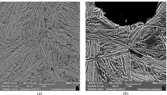
temperature to 300°C favors the formation of a finer microstructure with smaller isolated austenite blocks (Figure 4b). Because a lower austempering temperature results in a large undercooling of the austenite and a slow diffusion rate of carbon, the nucleation of ferrite plates rather than their growth is favored, resulting in a finer structure [15,16]. In Figure 4, for both austempering temperatures, it can be seen that the secondary sheaves are not continuous with the primary sheaves, i.e. they do not form a “branched” network. This corr e-sponds to a mechanism in which platelets, sub-units of ferrite which are not visible individually in micro-graphs of Figure 4, would nucleate close to the primary sheaf and successive platelets would extend the sheaf until it impinges another sheaf [15,17,18]. The primary sheaves tend to be in contact with, or closely ap-proach, the austenite grain boundaries and in some cases span the whole grain.
(a) (b)
Figure 4: SEM micrographs of samples austenitized at 930°C and austempered at: a) 370°C; b) 300°C.
The austempered samples were also analyzed by XRD. As shown in Figure 5, the intensities of the peaks representing the austenite phase increase for higher austenitizing and austempering temperatures. The volume fractions of retained austenite were calculated by the direct comparison method using the integrated intensities of austenite and ferrite peaks. The results are listed in Table 2. As expected, the retained austenite was observed to increase with increasing austenitizing and austempering temperatures.
Table 2: Calculated volume fractions (%) of retained austenite (r) and bainitic ferrite (b) or martensite (αm) in
austem-pered samples.
Phase 900°C/300°C 900°C/370°C 930°C/300°C 930°C/370°C
r (%) 1.7 22.9 18.4 28.1
bor αm (%) 98.3 77.1 81.6 71.9
The volume fraction of retained austenite depends on two competing effects: whereas an increase in the fraction of bainitic ferrite raises the carbon concentration in the austenite, bainitic ferrite also consumes austenite and hence, less remains to be retained. At low temperatures, it is the latter effect which dominates, leading to a fall in the amount of retained austenite. The very low value (1.7%) of retained austenite observed for the sample austenitized at 900°C and austempered at 300°C can be related to martensite formation during cooling from austempering to room temperature, as discussed in the characterization of austempered samples (see Figure 3b).
3.3 Mechanical properties and fractography
The results of mechanical characterization are reported in Table 3 for as-cast and austempered samples. As the austempering temperature was increased from 300°C to 370°C there was a decrease in the yield strength, tensile strength and hardness. This is because of the coarsening of both the austenite and ferrite with the in-crease in austempering temperature, as discussed earlier. Some combinations of strength and elongation found deserve special attention such as the specimen austenitized at 900°C and austempered at 300°C, which combines yield strength of 1173 MPa and tensile strength of 1406 MPa with an elongation until failure of 3%, outperforming the values of mechanical properties of Standard ASTM A897/06 (2011) for 1400-1100-02 class (former Grade 4). On the other hand, it is worth analyzing the low elongation values obtained for the samples austempered at 370°C, whose volume fractions of retained austenite were 22.9% and 28.1% respec-tively for austenitizing temperatures of 900°C and 930°C. There was no significant increase in ductility with increasing volume fractions of retained austenite when compared to samples austempered at 300°C. This result can be attributed to the effect of as-cast heterogeneities in the microstructure of ADI such as eutectic carbides and martensite formation during cooling after austempering [19,20,21]. The fracture surfaces of ten-sile test specimens were analyzed by SEM. Figures 6 and 7 show some typical fracture surfaces of ADI spec-imens.
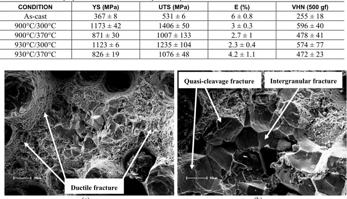
Table 3: Mechanical properties of as-cast and austempered samples.
CONDITION YS (MPa) UTS (MPa) E (%) VHN (500 gf)
As-cast 367 ± 8 531 ± 6 6 ± 0.8 255 ± 18
900°C/300°C 1173 ± 42 1406 ± 50 3 ± 0.3 596 ± 40
900°C/370°C 871 ± 30 1007 ± 133 2.7 ± 1 478 ± 41
930°C/300°C 1123 ± 6 1235 ± 104 2.3 ± 0.4 574 ± 77
930°C/370°C 826 ± 19 1076 ± 48 4.2 ± 1.1 472 ± 23
(a) (b)
Figure 6: Fracture surfaces of a specimen austenitized at 900°C and austempered at 300°C: a) ductile fracture regions; b) quasi-cleavage and intergranular fracture regions.
Ductile fracture
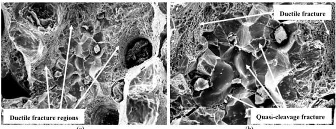
(a) (b)
Figure 7: Fracture surfaces of a specimen austenitized at 930°C and austempered at 370°C: a) ductile fracture regions; b) ductile and quasi-cleavage fracture regions.
As shown in Figure 6b, the fracture mechanism changes to a mode that is mostly brittle (intergranular fracture) in the intercellular regions. Cleavage fractures are transgranular low energy fractures that mainly derive from the separation of atomic bonds at low index atomic planes. In view of the fact that cleavage al-ways occurs along well-defined crystallographic planes within each grain, cleavage fractures change direc-tions when they cross grain or subgrain boundaries, graphite nodules and others, which explains the afore-mentioned river patterns observed. Cleavage fractures occurring commonly in high strength (low plasticity) microstructures tend to begin at the inclusions around the eutectic cell boundary rather than at the graphite nodule–matrix interface [19, 23].
4. CONCLUSIONS
The following main conclusions can be drawn with regard to the microstructural and mechanical characteri-zation of as-cast and austempered samples:
The austempering behavior of the ductile cast iron was strongly influenced by as-cast heterogeneities formed during solidification. Non uniform distribution of graphite nodules on the as-cast structure resulted in transformation gradients between intercellular areas and graphite-rich regions. As the austempering tempera-ture increased, both the ferrite and austenite were found to coarsen significantly. Austempering at 370°C re-sulted in coarser microstructures with large amounts of retained austenite blocks.
The increase in austempering temperature from 300°C to 370°C resulted in a decrease in the yield strength, tensile strength and hardness. Because of as-cast heterogeneities there was no significant increase in ductility for higher volume fractions of retained austenite. The fracture surfaces of tensile specimens showed mixed modes of fracture consisting of ductile fracture nearby graphite nodules and quasi-cleavage and/or intergranular fracture at intercellular regions.
5. BIBLIOGRAPHY
[1] GUNDLACH, R. B, JANOWACK, J. F., “A review of austempered ductile iron”. Proceedings of the 1st. International Conference of Austempered Ductlie Iron, v. I, pp. 65-68, 1984.
[2] TRUDEL, A., GAGNE, M., “Effect of composition and heat treatment parameters on the characteristics of austempered ductile irons”, Canadian Metallurgical Quarterly, v. 36, n. 5, pp. 289-298, 1997.
[3] PUTATUNDA S. K., KESANI, S., TACKETT, R., et al., “Development of austenite free ADI (austem-pered ductile cast iron)”, Materials Science and Engineering, v. 126, n. 7, pp. 435-436, 2006.
[4] KOVACS, B. V., “Development of austempered ductile iron (ADI) for automobile crankshafts”, Journal of Materials Engineering and Performance, v. 22, n.10, pp. 2783-2795, 2013.
[5] VOIGT, R. C., LOPER JR., C. R., “Austempered ductile iron - process control and quality assur-ance” ,Journal of Materials Engineering and Performance, v. 22, n. 10, pp. 2776-2794, 2013.
[6] MEIER, L., HOFMANN, M., SAAL, P., et al., “In-situ measurement of phase transformation kinetics in austempered ductile iron.” Materials Characterization, v. 85, pp. 124-133, 2013.
Quasi-cleavage fracture Ductile fracture regions
[7] PUTATUNDA S. K., “Influence of austempering temperature on microstructure and fracture toughness of a high-carbon, high-silicon and high-manganese cast steel”, Materials Design, p. 24, n. 4, pp. 435-444, 2003.
[8] BONNER, A. A., SHELTON, P. W., “The effect of cooper additions to the mechanical properties of aus-tempered ductile iron (ADI)”, Journal of Materials Processing Technology, v. 173, n. 6, pp. 269-274, 2005. [9] KIM, Y., SHIN, H., PARK, H., LIM, J. D., “Investigation into mechanical properties of austempered duc-tile cast iron (ADI) in accordance with austempering temperature”, Materials Letters, v. 62, n. 5, p. 357-360, 2007.
[10] PUTATUNDA, S. K., BINGI, G. A., “Influence of step-down austempering process on the fracture toughness of austempered ductile iron”, Journal of Materials Science and Engineering with advanced Tech-nology, v. 5, p. 39-70, 2005.
[11] TANAKA, Y., KAGE, H., “Development and application of austempered spheroidal graphite cast iron”, Materials Transactions, v. 33, n. 1, p. 543-557, 1992.
[12] LACAZE, J., “Solidification of spheroidal graphite cast irons: III. Microsegregation related effects”, Acta Materialia, p. 47, n. 14, p. 3779-3792, 1999.
[13] LARSON, A.C., VON DREELE, R.B., “General Structure Analysis System (GSAS), Los Alamos Na-tional Laboratory Report LAUR”, p. 86-748, 1994.
[14] GUO, X. L., SU, H. Q., WU, B. Y., et al., “Characterization of Microstructural Morphology of Aus-tempered Ductile Iron by Electron Microscopy”, Microscopy Research and Technique, v. 40, p. 336-340, 1998.
[15] YESCAS, M. A., BHADESHIA, H. K. D. H., “Model for the maximum fraction of retained austenite in austempered ductile cast iron”, Materials Science and Engineering, v. A333, p. 60-66, 2001.
[16] SPEER, J. G., EDMONDS, D. V., RIZZO, F. C., et al., “Partitioning of carbon from supersaturated plates of ferrite, with application to steel processing and fundamentals of the bainite transformation”, Current Opinion in Solid State and Materials Science, v. 8, p. 219-237, 2004.
[17] CHANG, L. C., “Carbon content of austenite in austempered ductile iron”, Scripta Materialia, v. 39, n. 1, p. 35-38, 1998.
[18] CAMPOS-CAMBRANIS, R. E., NARVÁEZ HERNÁNDEZ, L., CISNEROS-GUERRERO, M. M., et al., “Effect of initial microstructure on the activation energy of second stage during austempering of ductile iron”, Scripta Materialia, v. 38, n. 8, p. 1281–1287, 1998.
[19] YANG, J., PUTATUNDA, S. K., “Improvement in strength and toughness of austempered ductile cast iron by a novel two-step austempering process”, Materials and Design, v. 25, p. 219-230, 2004.
[20] ZHANG, J., ZHANG, N., ZHANG, M., et al., “Microstructure and mechanical properties of austem-pered ductile iron with different strength grades”, Materials Letters, v. 119, p. 47-50, 2014.
[21] BASSO, A., SIKORA, J., MARTÍNEZ, R., “Analysis of mechanical properties and its associated frac-ture surfaces in dual-phase austempered ductile iron”, Fatigue and Fracture of Engineering Materials & Structures, v. 36, p. 650-659, 2013.
[22] DAI, P. Q., HE, Z. R., ZHENG, C. M., et al., “In-situ SEM observation on the fracture of austempered ductile iron”, Materials Science and Engineering, v. A319-321, p. 531-534, 2001.