Evaluating Dynamic Signage for Emergency Evacuation using
an Immersive Video Environment
Roya Olyazadeh
A thesis submitted in fulfillment of the requirements for the award of the
Degree of Master of Science (Geospatial Technologies)
Dissertation supervised by:
Professor Dr. Christian Kray
Co-supervisors:
Professor Roberto Henriques
Associated Professor Oscar Belmonte Fernandez
Institut für Geoinformatik der Universität Münster
I
DECLARATION
I declare that this thesis entitled “Evaluating Dynamic Signage for Emergency
Evacuation using an Immersive Video Environment “is the result of my own research
except as cited in the references. The thesis has not been accepted for any degree and is
not concurrently submitted in candidature of any other degree.
Signature:
Name: Roya Olyazadeh
Place: Muenster, Germany
II
DEDICATION
To my beloved mother and father
مزیزع ردام و ردپ هب یمدقت
هک ولوچوک شاداد و
هم وا
ی
زورک
III
AKNOWLEDGMENT
Firstly I would like deeply to thank to my supervisor of this project, Professor Dr. Christian Kray, for the valuable supervision and advice. I would like to thank him for showing me some examples that related to the topic of my project. His willingness to motivate me contributed tremendously to my project. Besides I would like to thank my Co-supervisors, Professor Roberto Henriques at University of Nova in Lisbon, Portugal and Associated Professor Oscar Belmonte Fernandez at University of Jaime I in Castellon, Spain. Furthermore, I would like to thank the authority of Institute for Geoinformatics (IFGI) and The University of Münster (German: Westfälische Wilhelms-Universität Münster, WWU) for providing me with a good environment and facilities to complete this project.
In Addition thanks and appreciation to the helpful people at SITCOM lab to help me to work with available system called Immersive Video (IVE) specially Mr. Holger Fritze and Mr. Dennis Wilhelm.
IV
ABSTRACT
There are numerous reasons to evacuate a building in case of emergency; generally evacuation runs in case of constraints as fire, earthquake, indoor air pollution incidents, terrorist attacks and so on. There was a fire tragedy reported on January 28, 2013 in a night club in Brazil that many victims confused the exit sign with that for the toilet sign, where 50 bodies were found dead in toilet. It is reported that the victims lost their sense of direction due to the smoke [1]. Consequently the traditional static emergency signs are no longer effective especially in a complex building. They are not intelligent to decide how many people are using different exit, where the fire is and how much it may spread or how the evacuee will decide and think while they are in panic. They are several attempts to simulate the evacuation area and create a better model to dynamically lead the evacuee to exit. However creating such system is difficult because the prediction of behaviors in emergency incidents, modeling and examination in the real scenario are the biggest problems. Evacuation exercise are expensive and time consuming, as a result Virtual Environment (VEs) might be the feasible solution to create the emergency scenario and to study the physical, cognitive, and perceptual capabilities of the evacuees, letting them to experience and feel the emergency incident that are impossible to apply in the real world. This project presents the use of VE, called Immersive Video Environment (IVE) [2] to investigate and evaluate the possible dynamic signage inside a building to guide the evacuees to safety and exit. IVE system contains three screens with 140 degree from each other using 3 back projected wall at the same time. In this study dynamic signs inform the evacuee by following the exit signs cause of fire emergency and move towards the exit. Generally the user of VE is disoriented or discomforted due to navigation (Travel) part. As a result, following factors are evaluated by using some pre-defined questionnaire such as Simulator Sickness Questionnaire and NASA TLX:
1. The pre-movement time or response time to the dynamic signs. 2. Panic behavior or Decision making
3. Comfort of the system due to navigation part. 4. Performance of IVE
5. Realism of the simulation
V
Table of Contents
DECLARATION --- I
DEDICATION --- II
AKNOWLEDGMENT --- III
ABSTRACT --- IV
Table of Contents --- V
List of Tables --- VII
Table of Figures --- VIII
1. Introduction --- 1
1.1 Introduction --- 1
1.2 Related work --- 2
1.3 Problem statement --- 3
1.4 Aims and Objective --- 4
1.5 Research Methodology --- 4
1.6 Thesis outline --- 5
2. Literature Review --- 7
2.1 Introduction --- 7
2.2 Emergency Evacuation Systems --- 7
2.3 Dynamic Signage vs. Static --- 9
2.4 Virtual Reality (VR) --- 11
2.5 Usability Evaluation --- 12
3. Methodology --- 15
3.1 Introduction --- 15
3.2 Evacuee demand or task characteristics --- 16
3.3 Planning and preparation --- 17
3.4 Interaction --- 18
3.5 Performance measure--- 18
3.6 Evaluation --- 19
4. Design and Implementation --- 20
VI
4.2 System properties --- 20
4.3 Preparation --- 21
4.4 Video shooting and editing --- 22
4.5 Design and Overlay the dynamic signs --- 23
5. Experimental plan --- 25
5.1 Introduction --- 25
5.2 Experimental Design --- 25
5.3 Scenario of the test (Tasks) --- 27
5.4 Participants --- 27
5.5 Selected tests and guideline --- 27
5.5.1 Instruction (Guideline) --- 27
5.5.2 Simulator Sickness Questionnaire (SSQ) --- 28
5.5.3 Likert Scale Questionnaire --- 28
5.5.4 NASA Task Load Index --- 29
6. Results and discussion --- 30
6.1 Introduction --- 30
6.2 Decision making and response time --- 30
6.3 SSQ result (Comfort) --- 34
6.4 NASA TLX result (Performance) --- 35
6.5 Likert Scale Questionnaire result --- 36
6.6 Overall result (relationship between Time, Comfort and performance) --- 38
6.7 Discussion --- 39
7. Conclusion and Recommendation --- 41
7.1 Findings --- 41
7.2 Limitations --- 41
7.3 Recommendation and future work --- 42
7.4 Conclusion --- 42
Bibliography --- 44
APPENDIX A1: Instruction --- 49
APPENDIX A2: NASA TLX --- 50
APPENDIX A3: SSQ --- 54
APPENDIX A4: Likert Scale Questionnaire --- 56
VII
List of Tables
Table 2-1 Evacuation models ... 8
Table 5-1 Sequence of the tasks for each participant ... 26
Table 5-2 Available signs in each task ... 27
Table 5-3 Total weight for SSQ Symptoms [49] ... 29
Table 6-1 Correlation between likert scale questions ... 37
Table 6-2 Correlation between time, comfort and performance ... 38
Table A5- 1 Response time for each participant in each task ... 58
Table A5- 2 Response time in different task for male and female ... 58
Table A5- 3 SSQ results for each participant ... 59
Table A5- 4 Weights for SSQ based on the rate of the participant ... 59
Table A5- 5 SSQ result for men and women... 60
Table A5- 6 Likert scale Questionnaire results ... 61
Table A5- 7 Mean and Standard deviation for Likert scale questionnaire ... 61
Table A5- 8 NASA TLX scales for participants with their rated weight ... 61
Table A5- 9 NASA TLX calculation and results ... 62
Table A5- 10 Time, Comfort and performance for each user ... 62
Table A5- 11 Correlation for subscales in NASA TLX ... 63
VIII
Table of Figures
Figure 1-1 Example of static sign for emergency egress ... 2
Figure 1-2 Immersive Video environment (IVE) [2] ... 5
Figure 1-3 The diagram of the proposed methodology ... 6
Figure 2-1 RescueMe [12] AR application in 3D and 2D views ... 9
Figure 2-2 All the four different signs with Green-Red LEDs [23] ... 10
Figure 2-3 Type of Exit signs ... 10
Figure 2-4 Exit signs in Germany ... 11
Figure 2-5 IPT user in selection and manipulation task [35] ... 12
Figure 2-6 Sequential evaluation and Testbed [36] ... 14
Figure 3-1 Steps of methodology ... 15
Figure 3-2 Evacuee Demand ... 16
Figure 3-3 Planning and preparation ... 17
Figure 3-4 Interaction ... 18
Figure 4-1 Digital cameras ... 20
Figure 4-2 View of IVE ... 21
Figure 4-3 Plan of the selected area (3rd Floor) ... 22
Figure 4-4 Steps in designs and Implementation ... 23
Figure 4-5 Exit signs for IVE evacuation ... 24
Figure 4-6 Exit sign 4 inside one of the available task ... 24
Figure 4-7 Fire sign 5 inside one of the available task ... 24
Figure 6-1 No respond for fire sign when there is an exit door ... 31
Figure 6-2 Movement for the sign after they turned to new corridor ... 32
Figure 6-3 Calculation of pre movement time... 32
Figure 6-4 Number of errors per participant ... 33
Figure 6-5 Scatter plot indicates response time to the number of errors ... 33
Figure 6-6 Task difficulty level to response time and number of errors ... 34
Figure 6-7 SSQ test result ... 35
Figure 6-8 SSQ for Female and Male ... 35
Figure 6-9 NASA TLX result ... 36
Figure 6-10 NASA TLX for each participant ... 36
Figure 6-11 Mean and SD for likert scale for 8 questions... 37
Figure 6-12 Trend lines for normalized data ... 39
1
Chapter 1
1.
Introduction
1.1Introduction
There are numerous reasons to evacuate a building because of emergency. Generally evacuation runs in case of constraints as fire, earthquake, and indoor air pollution incidents (radioactive materials and toxic gases), terrorist attacks (sabotages, bombing) and so on. Occasionally it leads to the wrong exit and path and causes extra damages and fatalities. Everyone remembers the September 11, 2001. In this tragedy it was estimated between 13000 to 15000 persons successfully evacuated from the building [3] .The important factor is that how an evacuation system provides to solve the barriers successfully. There was a study of participants of September 11 at 2003 who mentioned the following factors while they were evacuating [3]:
1. Influence of decision making. 2. Knowledge of the location.
3. Information regarding what and where occurred and how to recognize it immediately.
4. Choosing and locating exit route.
5. Travel speed defined by age and gender [4].
6. Response time to the event (the pre movement and movement time). 7. Capacity of the route
2
building and it shall lead to the reduction in evacuation process and blockings in the exits.
This project presents the use of virtual environment (VE), called immersive video [2] to investigate and evaluate the possible dynamic signage inside a building (like hospitals, museums and airports) to guide the evacuees to safety and exit.
Figure 1-1 Example of static sign for emergency egress
1.2Related work
The traditional static emergency signs are no longer effective especially in a complex building such as Airport, hospital and etc. Recently such static systems are transformed to dynamic evacuation systems. They are so many attempts to simulate the evacuation area and create a better model to dynamically lead the people to exit. Karas Ismail Rakip [5] developed a 3D interactive human navigation for an indoor air pollution disaster. It is described that an optimum evacuation system consists of alarm devices, sensors and detector, evacuation lights and an indoor navigation system to help the people to exit [5].
Most of the models for evacuation are used Cellular Automata (CA) [6] [7] [8]. CA model is used in simulation because its operation process is very simple and it contains the models for individual movements. Varas [6] used a bi-dimensional cellular automata model to simulate an evacuation process from a classroom with full capacity. Evacuation times with and without obstacles were compared. In this model a personal tendency in each pedestrian to follow crowds were ignored.
Inhye Park [7] applied CA model to compute movement of evacuees with various velocities and connect with indoor positioning techniques RFID technology and present movement of individual evacuees for the 3D topological analysis. The problem of CA is that obstacle was fixed in integer number of cells.
3
Isobe [10] implemented a simulation of the evacuation of a room without visibility by an extended lattice gas model where the empirically observed behavior, adding more exits does not improve the situation in the expected way. Christakos [11] applied an ad hoc network to find the best path to an exit in a situation where paths may be blocked. RescueMe [12] employed using image-based localization such as IQEngine. Two models used in this system: one without any evacuation model just by path-finding algorithm and the other one by using the Rescueme Algorthim. The simulated people were randomly evacuated to the shortest-path exit door which adapted the shortest amount of time as well. Moreover LifeBelt [8] is based on Cellular Automata technique. This system is implemented as a Silent Directional Guidance for Crowd Evacuation. Application in a real site scenario, Linz station is one of the benefits of Lifebelt. In this model the decisions are made based on: Nearest exit (NE), Familiarity of the Exit, Exit population (EP), Exit capacity (EC) and Time to reach the Exit (TEA). LifeBelt progresses evacuation efficiency by more than 34.5 %.
Furthermore, several researchers developed models considering these three specific factors: Sound (Alarm), Tactile (Vibration) and Visualization (Light). Directional Sound Evacuation (DSE) [13] was examined with 75 individual participants in a road tunnel filled with smoke and visibility of 1 meter; the success rate was 87%. Lifebelt [8] and Activebelt [14] are the samples of tactile system for evacuation. They provide the directional guidance based on a variety of sensed measures including relative exit area dynamics [8].
All the works are mentioned above, have their advantages and disadvantages. Recently Ubiquitous Computing [15] or ubicomp systems are in the main area of computer science especially when physical objects are related with computers or mobile devices. Mark Weiser [15]was the first who proposed the idea of ubicomp. The main two characteristics of ubicomp are physical integration and spontaneous interoperation. This cannot be called ad hoc because ad hoc are autonomous systems and they cannot achieve spontaneous interoperation [15]. The GAUDI [16] system and the Rotating Compass [17] are examples of ubicomp which are designed to guide the people inside the complex building by using the dynamic signage [18]. Rotating compass [17] can be referred to visualization system where a public display demonstrates a compass with a rotating needle.
1.3Problem statement
According to the National Fire Protection Association [19]the fire at Düsseldorf airport killed 17 people and 62 injured. The following elements reported as the result of the fire [19]:
Lack of adequate communications
4
Lack of awareness of the building layout Lack of indoor geo-information
Lack of dynamic information No fire fighter accountability system
Insufficient command staff to manage the incident
Accordingly, if there were an adequate evacuation system, majority of people could survive from this disaster. So recently evacuation topic is changed to an active research. Safety is the critical issue in all and the purpose is guidance of the people who are in the danger to the exit. They have to evacuate the building in the shortest time with shortest path without confronting any obstacle or blocked route. Besides the invisibility, smoked area and huddle should be considered. However creating such system is difficult because the prediction of behaviors in emergency incidents, modeling and examination in the real scenario are the biggest problems. Evacuation exercises are expensive and time consuming. As a result VEs can be the possible solution to create the emergency scenario and to study the physical, cognitive, and perceptual capabilities of the evacuees, letting them to experience and feel the emergency incident that are impossible to run in the real world. This work shall improve the usability interaction of an Immersive VE in an emergency evacuation and preliminary result of decision making for a dynamic signs.
1.4Aims and Objective
The basic idea for this study is to use a public display system that uses contextual information to dynamically direct people to safety. The main idea shall improve the presentations of dynamic directional signs for quick and safe emergency evacuation. It is expected to accomplish the following objectives:
1. Collect information regarding the dynamic signage.
2. Create the virtual environment of emergency evacuation by using immersive video.
3. Study on the performance and effectiveness of the VE. 4. Study the behaviors of the people in of emergency egress.
5. Discuss the results for a suggestion of evacuation model based on them.
1.5Research Methodology
5
Immersive video system [2]. The immersive video (Figure 1-2) is achieved by capturing the images and sounds in the wide field of view between 140 to 360 degrees. Two major components of immersive video system:
1. Wizard: the wizard controls the sequence of video clips
2. Sensor information: by using XML files to store the sensor information about every clip.
Figure 1-2 Immersive Video environment (IVE) [2] The steps of the proposed methodology are described as follows:
1. To investigate travel demand and fundamental needs
2. To prepare the study area, shooting the video and apply to IVE.
3. To study on performance of interaction techniques such as time, accuracy, usefulness and ease of comfort (task completion time, convenience, accuracy, and realism )
4. To evaluate the result by statistical analysis and study on human behavior and decision making.
5. To come up with a model for evacuation system based on the results Figure 1-3 indicates the flowchart of this research methodology.
1.6Thesis outline
The thesis is in six chapters as detailed below:
Chapter one: It introduces the research topic, the background of the study, problem statement, research objective, scope and methodology.
Chapter two: This chapter covers literature review which is to explore methodology for emergency evacuation and dynamic signs in a Virtual Environment.
6
Chapter four: This chapter discusses implementations and preparation of this research. The steps contain; how to create the environment of emergency in IVE and how to overlay the exit signs inside the video.
Chapter five: This chapter presents the evaluation part and usability test for the study. Chapter six: This chapter discusses the results and analysis of this study from which necessary conclusion and recommendation will be made. Finally conclusions and recommendation for future study are discussed
Figure 1-3 The diagram of the proposed methodology
Collect infromation of Emergency dynamic Signage
Explore the user experience
Questionaire Results Creating the
enviroment of emergency evacuation
Apply to Immersive Video
Study on human behaviour
Study on the Pre Movement time
7
Chapter 2
2.
Literature Review
2.1 Introduction
This chapter focuses on all related works about dynamic signage evacuation systems, different models and testing environments. The first part 2.2 explains about the experimental works on evacuation systems based on different models. Part 2.3 investigates how static and dynamic signs are currently used in case of emergency egress and the last two parts will focus on Virtual environment, its usage for simulation a scenario and the possible evaluation methods
2.2 Emergency Evacuation Systems
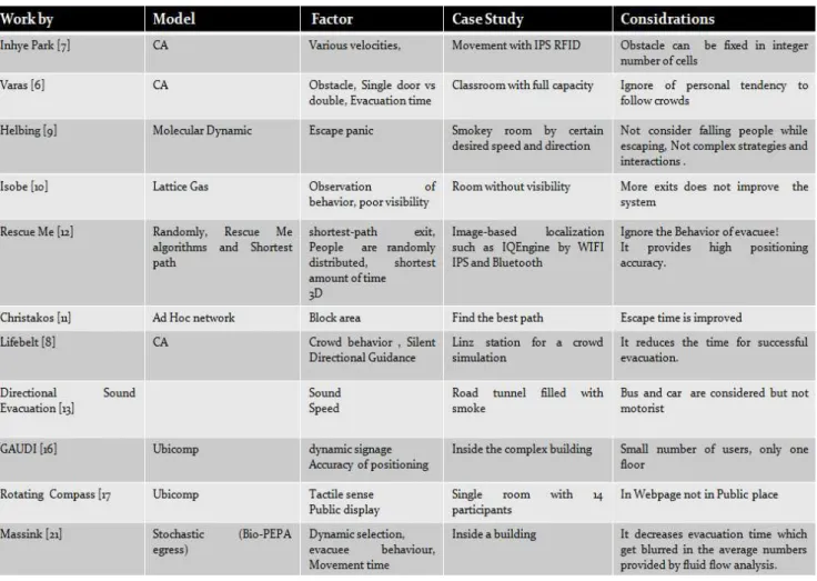
As mentioned in chapter one, there are numerous works related to evacuation and emergency situations. The model and the factor that they considered in their studies can be seen in Table 2-1 Evacuation models. These models might be categorized as follows:
1. Cellular Automata (CA) [7] [6] [8]. 2. Molecular dynamic [9].
3. Latice gas [10]. 4. Ad hoc network [11]. 5. Ubicomp [17] [16]
6. Shortest path algorithms [12]
8
Christakos [11] applied ad hoc network for an evacuation scenario for simply pedestrian simulator based on Helbing [9]’s escape panic simulator and the results shows improvement in escape time. Life Belt [8] examined CA model by comparing the following factors in Crowd dynamic: Time to reach to an Exit Area (TEA), Exit Population (EP) and Exit Capacity (EC). In this work, jamming at certain exits, while empty other exits were considered and it reduces the time for successful evacuation.
Table 2-1 Evacuation models
9
Autonomous Displays) [16] consists arbitrary number of autonomous wireless displays and a navigation server. It is automatically assigned the dynamic signs with the current location of the user.
Figure 2-1 RescueMe [12] AR application in 3D and 2D views
2.3 Dynamic Signage vs. Static
The term of evacuation dynamic has to be understood on different level such as: physical, physiological, psychological, and social [20]. This work tests particularly physical and psychological level in a VE to determine the differences between static and dynamic signs. In this study dynamic signs inform the evacuee by following the exit signs in case of fire emergency and move towards the exit. Directional signage systems such as [16], [17], [21] are designed to support users in different environment.
10
Figure 2-2 All the four different signs with Green-Red LEDs [23]
Dynamic signs shall follow the design of static sign. Emergency signs contain elements that evacuee should locate and identify the exit door. Exit signs show a long way over the past years. The English word "EXIT" is derived from the Latin word which means "To go out" [24]. They shall be visible from any direction and the size of the signs are dependent to structure of building approximately 12” long, 8” high. Mainly, the emergency signs follow two types of sign (Figure 2-3): Exit sign and the running man sign. The running man symbol was designed by Japanese named Yukio Ota at international contest in 1985 [25]. In European Union, Australia, New Zealand, China and Japan, Emergency exit signs have green lettering or mostly the running man sign (Red is used to show prohibited area like fire region). The running man sign has two pros: Firstly it is a pictogram so it can be understood even by people who don’t speak the same language of that country indeed it is green that is the color of safety. In the other hand the Emergency signs have either red or green lettering but typically red color in United States and Canada [24]. There might be a discussion which color (Green or Red) is more visible in smoky area. Emergency signs must have higher luminosity for smoke conditions and lower luminosity for free conditions [26].
Figure 2-3 Type of Exit signs
11
consequently the signs with white background require more luminance than those with darker backgrounds.
Rubini [29] compared the green and white background in different smoke area. It is pointed that visibility of a sign depends on relative contrast to the background and can be express by Weber contrast as:
(1)
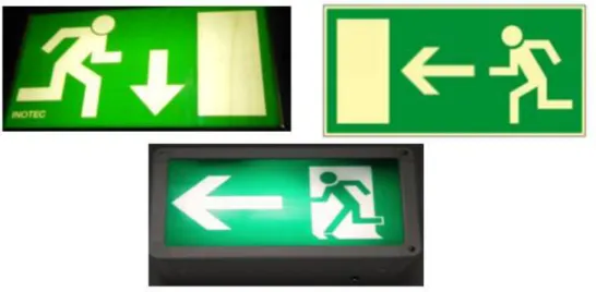
Where LT is the luminance of the object and Ls is the luminance of the background. Wright [30] compared different kind of dynamic sigs like LED or electroluminescent. Two of these signs are comprised of green colored background with white exit symbol and green LEDs forming symbols respectively. The study tries to distinguish the difference between the maximum viewing distance in a smoke area and the results shows there were no significant differences in all 15 tests. Collins [26] studied on electroluminescent signs and he pointed out that signs with illuminated letters and opaque backgrounds in some cases are more visible than panel-faced signs. Figure 2-4 illustrates some available signs in Germany where this research is applied.
Figure 2-4 Exit signs in Germany
2.4 Virtual Reality (VR)
computer-12
synthesized world in which the user will be able to easily navigate from one location to another one and interact with objects and perform various activities [31]. The word “Navigation” has been used in term of the process of defining a path to travel through any environment. Navigation refers as exploration, walking, flying, motion, travel or way-finding in different VEs [31, 32, 33, 34]. Generally the user of VE is disoriented or discomfort due to navigation part. Two type of navigation or travel can be distinguished: Active and passive. In active, the user can interact with interface while in passive the navigation is predefined. Most common VEs have used head-mounted display (HMD) or CAVE systems. Figure 2-5 shows an example of Immersive VE called immersive projection technology (IPT) [35].
Figure 2-5 IPT user in selection and manipulation task [35]
2.5 Usability Evaluation
Virtual Environment (VR) is a new type of Human Computer Interaction (HCI) technique. Usability evaluation methods are one of the key factors in VR since they promise to obtain an enhanced system, higher performance and comfort for users. “Usability can be broadly defined as “ease of use” plus “usefulness”, including such quantifiable characteristics as learn-ability, speed and accuracy of user task performance, user error rate, and subjective user satisfaction” [36]. There are different ways to test the usability of the VE. One of them is called “Think Load”. In some VEs, voice recognition is used to render the Think load protocol. The common technique engages to address a tracking camera to record the synchronized video from user and interface which both are visible by evaluator. There are various usability evaluations available; following are some example [36]:
13
Formative: It is used to assess usability problem and design ability that it is mostly based on qualitative result.
Heuristic or Guideline-based [37]: This method is applying a set of design guideline for the users; it is difficult to predict. This test is addressed for the expert user (Task Descriptions Sequences & Dependencies)
Questionnaire: The test can be run by set of defined questionnaire. This is more convenient way to evaluate the users. Nowadays there are different types of evaluation and workload questionnaire are available. Next part will explain some of the examples. Interview: Interview may let the evaluator gather more information than questionnaire even some factor which they were not considered in the test and later it shows that it has big influence on the results.
Summative: This is way of statistical comparison of different interface design (qualitative and quantitative)
Testbed [38]: This test is introduced by Bowman and it is composed of Heuristic and Quantitative performance.
Sequential evaluation [39]: It is collected of formative, Summative and Heuristic (Both Design and evaluation).
Figure 2-6 presents the test bed and sequential evaluation approach [36].
The questionnaire appears in the fact that evaluator is trying to measure different kind of factors likely such performance, presence, comfort, ease of use, etc. So based on these factors there are different type of questionnaire. Following describe briefly the most common questionnaires in VE.
Questionnaire to test the comfort of the user:
Simulator sickness Questionnaire (SSQ) [40]: It is the most famous questionnaire to define the motion sickness developed by Robert Kennedy. This part is explained more in section 5.5.2.
Questionnaire to test presence:
Presence Questionnaire: PQ has designed to measure presence in VEs. The factors that is contributed to measure presence are: Control, Sensory, Distraction and Realism factors [41]
14 Questionnaire to test performance:
NASA Task Load Index (TLX) [42]: The NASA TLX applies six dimensions to evaluate workload: mental demand, physical demand, temporal demand, performance, effort, and frustration. More information can be found on 5.5.4.
VRUSE [43]: It is based on the attitude and perception of its users, indeed system performance on presence is included. The rates change from 1 to 10 in terms of never to always, cluttered to uncluttered, impossible to easy confusing to clear VRUSE include the total 100 questions and it is not appropriate to delete the questions but it is possible to remove the total section from questionnaire. Following factors are assign for VRUSE: 1) Functionality 2) User Input 3) System Output (Display) 4) User Guidance and Help 5) Consistency 6) Flexibility 7) Simulation Fidelity 8) Error Correction/Handling and Robustness 9) Sense of Immersion/Presence 10) Overall System Usability.
Software Usability Measurement Inventory (SUMI) [43]: SUMI produces six scaled scores: Efficiency, Aspect, Helpfulness, Control and Learn-ability in three different levels (Agree, Undecided and Disagree).
Subjective Workload Assessment Technique (SWAT) [44]: SWAT applies three levels (low, medium and high) to produce a single rating scale workload. It is considered that TLX has better scale for measuring the mental factor than SWAT.
15
Chapter 3
3.
Methodology
3.1 Introduction
This chapter specifies the methodology for this study. Bowman [38] and Tan [45] proposed their methods to apply to Virtual Environment (VE). In this study their methods has been used to create the simulation of dynamic evacuation signs in an Immersive Virtual Environment by using Immersive Video. Part 3.2 describes the evacuee demands for an emergency incident; besides part 3.3 and 3.4 will express that how it is implemented in VE. Finally part 3.5 and 3.6 explains the performance and evaluation test study. Evaluation test study also described in chapter two and five widely with all the possible statistical analysis. Figure 3-1 represents the steps of the proposed methodology; they can also be described as follows:
1. To investigate travel demand and fundamental needs
2. To prepare the study area, shooting the video and apply to IVE.
3. To study on performance of interaction techniques such as time, accuracy, usefulness and ease of comfort (task completion time, convenience, accuracy, and realism )
4. To evaluate the result by statistical analysis and study on human behavior and decision making.
5. To come up with a model for evacuation system based on the results
Figure 3-1 Steps of methodology Evacuee demand
Prepration
Interaction
Performance measure
16
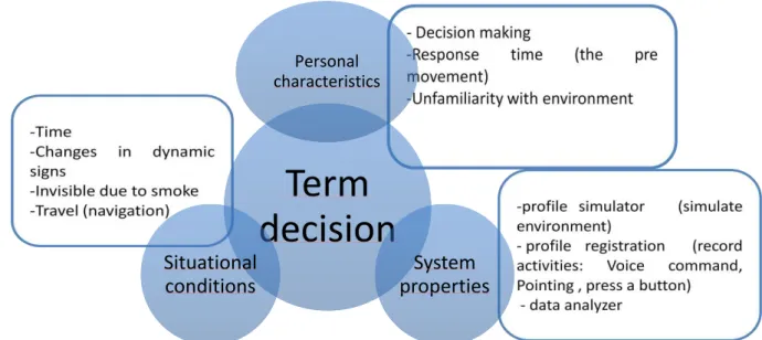
3.2 Evacuee demand or task characteristics
The first step towards the methodology of this work gains the possible characteristic demands for Evacuee. Some factors from literature review are concluded into this study such as escape panic, poor visibility or smoky area, response time, speed. Figure 3.2 shows the factors that are considered in this study.
The first part of evacuee demand is personal characteristics. This part mostly is connected to the situational conditions such as travel, time and poor visibility. Nevertheless it can be expressed as decision making in panic situation. In [20] , Panic describes as an irrational behavior which the people compete to dwelling to exit. Panic is an unexpected event and due to that it is not possible to model it and to test it quantitatively. The best option is to call it as decision making instead of escape panic. Speed of the traveler changes due to their age, the location (Corridor or Stairs) and the situation of them. If they are in a relaxed situation, the observed free velocity is around 0.6 m/s and for normal and nervous conditions are around 1 m/s a and 1.5 m/s respectively [9].In addition, one study [4] mentioned that the maximum walk speed for male is 1.6 m/s and for female is about 1.4 m/s . Upward walking speed is depended to the age, sex and length of the stairs and is around 0.391 to 1.16 m/s [20]. Accuracy is ignored here but the test runs with the running velocity situation. Concerning the egress time, 5 classes are distinguished: 1) detection time, 2) awareness time, 3) decision time, 4) reaction time, and 5) movement time. Generally, the first four classes called the pre-movement time (response time). This pre-pre-movement time is going to be tested by how and when the users react while the dynamic signs are changed. These results shall be helpful afterward to model the evacuation and decision making analysis.
Figure 3-2 Evacuee Demand
Term
decision
Personal characteristics
System properties Situational
17
Figure 3-2 explains the task characteristics are separated to 3 different categories: personal characteristics, situational characteristics and system properties. The above paragraph talked about the first two classes. System properties are divided to three parts: profile simulator, profile registration and data analyzer [45]. Profile simulator represents the virtual environment and dynamic virtual objects inside it (in this study dynamic signs). Profile registration records all the activities and behavior of the users; this is completed by a tracking camera or a voice command. More descriptions are explained in Interaction part (3.4) called Selection. The last element of the system is data analyzer that works to evaluate the quality and quantity of data collection. This also called as Evaluation process that is the last step of VE (part 3.6 and result).
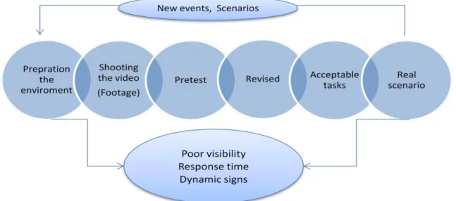
3.3 Planning and preparation
Planning plays an important role in this subject to complete the experiment. Figure 3-3 gives you an idea about the steps in planning and preparation section. As this study focuses on Immersive Video, the first part prepares the environment for the video shooting. This is accomplished by answering these questions: Where is the place? How is it possible to apply footage video? Where are exit doors located? How can the evacuee reach them (Corridors and stairs)? The next steps are to find the suitable camera for shooting the video and pretest the recorded video to see if it is realistic. Later on the tasks are defined and the acceptable task should be shifted to the respective scenario.
18
3.4 Interaction
Interaction refers to how the participants or users interact with the system. According to the methodology of Bowman [38], Interaction Technique (IT) contains three major processes: Navigation, Selection and Manipulation (Figure 3-4). In this work, navigation which is called travel or motion as well; it is how the user directs automatically to the exit. Moreover the velocity and direction will be adapted automatically. Indeed selection is how the user reacts with dynamic signs and environment. The user indicates to the signs by pointing to the left or right. Finally the manipulation is how the system acts while it is running. The main object in this step is how to change the exit signs inside the IVE in a specific time, position and size. Normally the selection and the manipulation are connected somehow together. In this study case, manipulation is implemented before selection.
Figure 3-4 Interaction
3.5 Performance measure
The methodology is assigned to obtain information about performance in IVE task. “Performance may be roughly defined as the effectiveness in accomplishing a particular task.” [46]. This part is highly related to the task characteristics. Bowman [38] pointed out that performance is speed or task completion time, accuracy, ease of use and ease of comfort. In VE, presence (Involvement and Immersion) and realism might be also a valuable measure [47, 41] . “A VE that produces a greater sense of immersion will produce higher levels of presence [41]”. Some of them are easy to measure and they are quantitative and the others are depended to decision making and human behavior thus they are called qualitative. As mentioned before accuracy is not a significant case in this study in case of metric like speed or distance. There are two main ways to measure the
Travel or
19
performance: Primary and secondary measure workload. In this research, performance is introduced as follows:
6. The pre-movement time or response time to the dynamic signs. 7. Comfort of the system
8. Performance of IVE 9. Realism of the simulation
10.Panic behavior or Decision making
The next part and chapter 5 will explain how it is possible to measure these factors.
3.6 Evaluation
The last step of this methodology is evaluation of the system. So based on the result, it is possible to suggest special model for the evacuation. The effectiveness of virtual environments (VEs) has often been linked to the sense of presence reported by their users. The evaluation of dynamic signage IVE is divided to 4 parts:
1. Tracking camera to record the video from both participant and graphical view. It is planned to trace the evacuee behavior and their response time to the dynamic signs
2. NASA TLX questionnaire to define the performance of the IVE
3. SSQ questionnaire to discover the comfort of the system specially motion sickness.
20
Chapter 4
4.
Design and Implementation
4.1 Introduction
In this chapter the design and implementation of the IVE components for a dynamic evacuation signage are described. Filming the video to simulate the user’s experience as a virtual environment for emergency egress is one of the component of this research. System properties of IVE are explained in part 4.2. Section 4.3 focuses on the preparation of the test plan, location and dynamic signs. Section 4.4 and 4.5 will talk about the editing and overlays. The purpose of these tasks is then to show how, under these assumed conditions, a successful system can be constructed for a Virtual Environment to feel the reality of emergency exit.
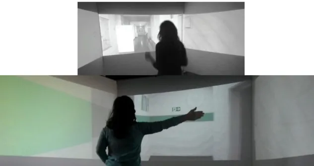
4.2 System properties
IVE system contains three screens with 140 degree from each other using 3 projectors at the same time. Generally the IVE System composed of the following:
- 3 digital cameras (CANON; right, center and left camera), Figure 4-1. - 3 back projected wall that creates wide screen (140 degree),
- Figure 4-2
- Software (VLC player)
- Adobe Pro (To edit, synchronize of video clips and overlay of exit signs)
21
Figure 4-2 View of IVE
4.3 Preparation
The first step of implementation is selection of the location that emergency egress can be applied. The geometry of the building, size of the corridors and door locations are important issues. It is intended to choose a building that it has the following characteristics:
1. There are several exit ways from one floor which dynamic evacuation system can be applied to it.
2. The corridors are not tiny that moving platform can move easily. 3. The exit signs are visible while shooting the video.
4. The corridors are different that the user shall not feel the same in the tasks.
5. There are no people while shooting the video (human factor like crowd is not interested in this study).
6. The building and corridor should be new for the participants, this is a key to enable evacuee to evacuate an unfamiliar building rapidly and securely in an emergency condition.
From the above discussion, the final place has been chosen which has all of these qualities. Figure 4-3 demonstrates the plan of the floor, Exit doors and corridors.
22
Figure 4-3 Plan of the selected area (3rd Floor)
4.4 Video shooting and editing
23
the dynamic signs inside the task. Since there are just 7 video clips and they have to be merged to create a real evacuation scenarios, The mirror effect (Horizontal flip) has been applied to some of them while it helps the user not to feel the same situation as previous task. The final tasks after adapting the running speed are around 30 to 40 seconds per trip. Other information about the experimental design is available in section5.3. Following Figure 4-4 indicates the steps to prepare the final task.
Figure 4-4 Steps in designs and Implementation
4.5 Design and Overlay the dynamic signs
After generating the tasks from the clips, it is time to design the exit signs. As it is mentioned before, this part is called manipulation. These signs follow the German standard. Figure 4-5 illustrates all the possible signs which are helpful in this special simulation of emergency exit. They are called from 1 to 6 consequently and later they are known by these numbers. These signs were added to the proposed tasks and in several specific cases they are changed for example from right to left or from exit to fire (Sign 6 to Sign5). Figure 4-6 and Figure 4-7 confirm the exit signs in this IVE simulation. It was also planned to add smoke and fume to the task that the users feel more reality. These effects can be applied easily in Adobe After Effect 6. The final video with smoke was around 20 GB just for 30 seconds and it was not possible to render in the IVE system. The video has to be compressed by one of the available video editing to the smaller version and the final result drove the less quality. Finally the smoke effect has been removed from the final task while in future possible solution might be found for that.
Video shooting
•Define the start and end point
•Footage video
Editing
•Synchronization
•Filtering and triming
•Stabilization
•Speed/duration adaption
•Horizontal flip
•merge the clips
Apply dynamic
signs
•Design the exit sign
24
Figure 4-5 Exit signs for IVE evacuation
Figure 4-6 Exit sign 4 inside one of the available task
25
Chapter 5
5.
Experimental plan
5.1 Introduction
This chapter represents a review of the experimental design, instruction guideline and available workload subjective assessments (SSQ and NASA TLX). These methods are presented here in this chapter. Additionally results and analysis will be discussed in the next chapter. The chapter starts with a preliminary description of experimental design of the whole work such as goal, tasks, rotation material and expected outcomes. There are various publications regarding the evaluation analysis methods. In this research the most common and important of them has been chosen. The latter is an introduction to selected test and guideline.
5.2 Experimental Design
Design of experiment (DOE) or experimental design is the procedure that defines how information will be gathered in the experiment. The principle of DOE explains: How many factors the design will have? How to control the conditions? Did the manipulation truly work? Which kind of materials can be used? And etc. The steps for this research are as follows:
Goal:
- Identify how people react with IVE in evacuating the building. - Discover the response time when they realize the changes in the sign. - Identify the effort, performance and comfort of the IVE.
Task:
- Design 6 signs which follow the German standard (The running man symbol)
26 Rotation:
- Randomized experiment
- Randomized experiment makes sure that repeating the scenarios for all participants will not affect the results.
Participant ID
Tasks
1 1 2 3 4 5 6 7 8
2 8 7 6 5 4 3 2 1
3 4 5 6 7 8 3 2 1
4 4 3 2 1 5 6 7 8
5 6 7 8 1 2 3 4 5
6 2 4 6 8 1 3 5 7
7 1 3 5 7 8 6 4 2
8 3 6 5 8 1 7 2 4
9 7 8 1 6 3 5 4 2
10 4 3 6 5 2 1 7 8
Table 5-1 Sequence of the tasks for each participant
Procedure:
- The participants arrive to the lab, read the instruction and sign it. - Tracking camera starts to record.
- They are asked to stand and act like when they are running. - They start the test (6 minutes).
- Stop the video camera to record.
- Hand out the questionnaires ( SSQ, Likert Scale questionnaires and NASA TLX around 15 minutes)
Materials:
- IVE system
- Tracking camera (Nikon)
- Printed version of questionnaires.
Potentially interesting outcomes:
- Response time in two different exit signs.
- The behavior of the participants when they see a sign changes. - Comfort of the system by SSQ.
27
5.3 Scenario of the test (Tasks)
8 scenarios have been managed for this experiment in which each of them last around 30 to 40 seconds for a trip from start point to the exit door. In the entire scenario, the exit signs will be varied. They are some differences between them. They are planned from easy to difficult level. The signs will be changed just one time in a task for the easiest level and two to three times for the difficult one (Table 5-1). The task will be selected randomized by the evaluator and users don’t interact with the interface
Task Difficulty Sign 1 Sign 2 Sign 3 Sign 4 Sign 5 Sign 6
1 Medium 2
Changed
2 Used - - - Used
2 Easy Changed Used - - - -
3 Easy - - Changed Used - -
4 Easy - - Used Changed - -
5 Medium - - Changed Used Used Changed
6 Difficult - - Used
Changed
Changed Used
Used Changed
7 Difficult Changed Used - - Used Changed
8 Medium Used
Changed
Changed Used
Table 5-2 Available signs in each task
5.4 Participants
The test participants were 10 people (5 Female, 5 Male) who come from different nationalities not specially Germany. Most of the participants do not speak German while they leave in Germany for a while. They all are educated in different background and participants ages ranges from 21 to 30 year (M=27).
5.5 Selected tests and guideline
5.5.1 Instruction (Guideline)
28
1. The participation is free and the user can choose to either stay or leave. 2. The user can withdraw from the experiment any time he wants.
3. The purpose of the study. 4. The procedure of the test.
5. All the information from the user is for scientific purposes and is not going to be used for any other kind of reasons.
5.5.2 Simulator Sickness Questionnaire (SSQ)
Generally the user of VE is disoriented or discomfort due to navigation (Travel) part. As a result, in this test, SSQ used to test the motion sickness of the current VE system. It is the first time which footage video is applied to this IVE and it could be helpful to find out the discomfort of participants while they are dealing with the test.
Kennedy et al [40] embedded the Simulator Sickness Questionnaire (SSQ). The SSQ uses a questionnaire to measure the three weights: Nausea, Oculomotor and Disorientation in a virtual environment (Table 5-3; the users report the degree of 16 symptoms (APPENDIX A3: SSQ) from none, slight, moderate to severe [48]. The total SSQ score is achieved by multiplying the weights to the scale scores. More information about how to calculate the final result can be seen in [49]. In this study it is intended just to use the post questionnaire for the SSQ. Young [50] described that people who were just exposed to a post questionnaire after VE were less likely to report motion sickness than who were delivered the both pre and post questionnaire. Nevertheless, the SSQ can be significantly biased by demand characteristics and also caused more distortion due to illness of the participants [50].
5.5.3 Likert Scale Questionnaire
29
Table 5-3 Total weight for SSQ Symptoms [49]
5.5.4 NASA Task Load Index
30
Chapter 6
6.
Results and discussion
6.1 Introduction
This chapter indicates the results in six sections. The first part explains the result of human behavior from tracking camera and their response time. The second part focuses on SSQ test result. Third part clarifies the performance of the system by NASA task. Then it is talked about the realism of the system. Finally an overall result and comparison between time response, comfort and performance of the users has been discussed.
6.2 Decision making and response time
In this part, the result of the response to the dynamic signs has been discussed. The result of the tracking camera indicates the following outcomes as human decision making:
1. In a few cases (2 out of 10), the participant confused between right and left, but finally they have chosen the correct way.
2. Mostly the error appeared for the Fire signs (8 out of 15). The user could not recognize the changes of the exit sign (sign 6) to the fire sign (Sign 5) when they saw the exit door (Figure 6-1).
3. Some of the users (4 out of 10)decided not to act like walking or running however the result shows after some tasks, they (3 out of 4) started to move their bodies while they experience the running simulation in IVE. In a simple way it can be said that the users felt the evacuation is running.
4. A few number of the users (3 out of 10) pointed out to the left or right after the simulation turned to another corridor (late movement). It can be explained the pre movement time to shift to other clips was not enough for some users (Figure 6-2).
31
6. Sometimes they responded to the dynamic signs by sounds (like wow the sign changed, oh no, was it changed? etc) instead of pointing especially when they recognized the changes a bit late.
7. Learning the situation is not affecting their reaction to dynamic signs and even sometimes they realized the changes in signs later in the last tasks than the beginning (It has been seen in 3 users). This is the result of mentally being tired or bored. The total time of the test is around 5 minutes so it can be concluded the human cannot decide quickly and correctly in rush situation after some minuets. 8. The evacuation success was around 80% (15 errors during the 8 tasks of 10
participants). So the future work will recommend for the full success. 9. The summery of the results can be seen in http://youtu.be/4E-bO5nsDTo:
Figure 6-1 No respond for fire sign when there is an exit door
32
Figure 6-2 Movement for the sign after they turned to new corridor
Figure 6-3 Calculation of pre movement time
33
fire sign design (5-6) is 1.18 seconds. This indicates that the exit door influenced the participant to react later. Figure 6-4 presents the line chart for the total number of errors per participant in the test and Figure 6-5indicates the scatter plot for number of errors to their response time. It can be concluded from the trend line that errors is not affecting to their response. In the other hand the maximum response time is not related to maximum errors. The task difficulty has been defined for the entire task. The task is named hard if the signs change more than two times in a trip and the time difference for change and turning to another corridor is less than 3 seconds. Figure 6-6 shows that response time is not related to task difficulty nevertheless the number of errors appear more while the task become harder. ASdditional statistical analysis can be run for this part later.
Figure 6-4 Number of errors per participant
Figure 6-5 Scatter plot indicates response time to the number of errors
0 0.2 0.4 0.6 0.8 1 1.2 1.4 1.6 1.8 2
0 2 4 6
R e sp o n se tim e
Number of errors
34
Figure 6-6 Task difficulty level to response time and number of errors
The response time for each task (Male: M=0.98, Female M=0.82) with t test, there is a significant difference for groups of male and female (t (14) = 2.85, p = 0.01, Cohen's d=0.55).
6.3 SSQ result (Comfort)
35
Figure 6-7 SSQ test result
Figure 6-8 SSQ for Female and Male
6.4 NASA TLX result (Performance)
36
Figure 6-9 NASA TLX result
Figure 6-10 NASA TLX for each participant
6.5 Likert Scale Questionnaire result
It was planned to prepare a specific questionnaire apart from NASA and SSQ. The aim of this questionnaire is to identify the realism of evacuation simulation in IVE. Totally 8 questions were initially written in technical terms (APPENDIX A4: Likert Scale Questionnaire) and the likert scale has been applied for the answers to address cross correlation between the different questions. Figure 6-11 shows the mean and standard deviation for these 8 questions. The following results can be concluded:
1. They could see the signs clearly.
2. They were happy with the idea of dynamic signage.
3. They were evacuating the building and the simulation looks real for them. 4. They understood differences in the task and they were happy with the design. 5. They thought that they have recognized the changes in sign in the exact time. 6. Mostly they did not feel rush or panic.
7. Mostly they recommend that they prefer the sound signs synchronized with Graphic signs in the environment to recognize the situation clearly
0 50 100
1 2 3 4 5 6 7 8 9 10
NASA TLX
37
Figure 6-11 Mean and SD for likert scale for 8 questions As might be expected from
Table 6-1, a relatively medium correlation was found between questions (4, 7), (5, 8), (1, 8) and (4, 8). So we can say that
- The users who could see the signs in current time, they were happy with the design.
- The users were happy with the idea of dynamic evacuation indeed they think that the simulation looks real.
- The users felt that they are evacuating a building and in their opinion the simulation looks real.
- The users who could see the signs in current time, they think that the simulation looks real.
-Column1 Q1 Q2 Q3 Q4 Q5 Q6 Q7 Q8
Q1 1.000
Q2 0.000 1.000
Q3 -0.102 0.000 1.000
Q4 0.304 -0.404 0.373 1.000
Q5 0.253 0.202 -0.310 0.277 1.000
Q6 -0.152 0.705 -0.371 -0.138 0.345 1.000
Q7 0.492 0.164 0.452 0.674 0.374 0.112 1.000
Q8 0.609 -0.243 -0.373 0.556 0.647 0.138 0.449 1.000
Table 6-1 Correlation between likert scale questions
Apparently this is the final conclusion of this questionnaire: The users were agreed with realism of the evacuation simulation in IVE, they were satisfied with the design and the idea of dynamic signs although they did not feel any panic and rush.
0 1 2 3 4 5
1 2 3 4 5 6 7 8
38
6.6 Overall result (relationship between Time, Comfort and
performance)
In this part, it is important to find the relation between time, comfort and performance. As mentioned before SSQ questionnaire have been known to test the comfort of the users and NASA TLX has been assessed to discover the performance of the system. Therefore there are three variables available for each participant. One of them is response time and the two others are the overall scores from SSQ and NASA TLX results (Out of 100). The first step is to normalize these 3 variables. In Appendix A5 the final normalized data is accessible. Figure 6-12 demonstrates the trend lines for normalized data. No pattern can be seen (i.e., if one variable increase, other variable increase or decrease). For this situation (for time instances or comfort instances the performance is always high. So maybe time and comfort don’t affect performance highly. As a result for the next step regression analysis is desirable.
Table 6-2 clarifies the correlation between time, comfort and performance. Correlation does not imply causation. It means between two variables does not necessarily imply that one causes the other. The best way to explicate the relation between these three variables is to use the regression. The relation is explained if their time response has been affected by comfort and performance or not.
Correlation Time Comfort Performance
Time 1
Comfort -0.488 1
Performance 0.214 0.263 1
Table 6-2 Correlation between time, comfort and performance
39
Figure 6-12 Trend lines for normalized data .
Figure 6-13 Scatter plot for Overall result (comfort and performance to time)
6.7 Discussion
40
response. Since all the participants were in a healthy condition, it can be concluded being tired or being in rush affected their result and this can also be happened in a real scenario.
In section 3.2, the panic situation and decision making were discussed. Apparently, there were two different result from likert scale and NASA TLX questionnaire in the issue of being in rush or panic. In likert scale questions, most of the participants declared that they did not feel any rush or panic meanwhile some of them reported low level. In contrast, NASA TLX assessment indicated high temporal demand score. That means the participants felt time pressure and rapid pace. It might be a misunderstanding of the question for all participants. So the participant felt rush during the test but not panic.
- Rush means: A sudden forward motion, hurry, surging emotion
- Panic: A sudden overwhelming feeling of terror or anxiety, esp. one affecting a whole group of people.
41
Chapter 7
7.
Conclusion and Recommendation
7.1 Findings
This work presents the aspects of using an immersive virtual environment (IVE) for the study and measurement of human behavior and decision making in the context of emergency evacuation. The results of this study prove that the IVE can be an effective tool. The performance of this simulation was high in temporal and mental demand which it was the purpose of this research. Generally the performance and the comfort of the system show interesting results in the emergency simulation and footage video for VE. There were a significant different in term of discomfort between men and women and the results of their response time had significant difference. By users rating, the realism of the simulation has been confirmed. The IVE can be used for future experiment investigation such as way finding. For response time experiment, some errors and significant variation were observed during the individual test.
7.2 Limitations
42
video were huge and it generates small pauses during the experiment and due to footage video, dynamic signs had small jumps in some of the sequences. .
7.3 Recommendation and future work
In this research, dynamic evacuation signs were highlighted. From the user’s recognition, it is understood that sound and smoke can be also influenced them to feel more reality or to realize the changed in the signs faster. So for next study it is recommended to add these factors to experience the result. From the evaluator experience, it is recognized that users gender and even nationality also influence to their time response so to have more accurate result, more user test will be suggested for further study.
In this work to evaluate the behavior and the pre movement time for the user, the tracking camera and normal manual calculation of their behaviors has been assessed. By merging of real and virtual elements, it helps the users to physically interact with the VE and they can be fully involved that uses the contexts of human activity and location in VEs. For future it is recommended such tools like Kinect Microsoft to be used. Kinect is a new technology from Microsoft which these days are mostly used for game or advertising. It is a cost effective tool and programming with Microsoft Kinect cannot be difficult while it will deliver more accurate and precise results. As
The statistical analysis for this study to discover the exact relationship between time, comfort and performance were not successful because there were not sufficient amount of data. Further statistical analysis can also be suggested when there are number of enough participants available.
7.4 Conclusion
This work presents the aspects of a virtual environment by using Immersive Video for the study of emergency evacuation and measurement of human behavior in the context of activity. The proposed system helps to yield more reliable information about human behavior and decision making in emergency egress and creating a model in VE. Locations, timing, duration and speed, helping from dynamic signs can be considered as decision-making process subject to emergency evacuation.
The main conclusions are:
43
- The comfort and the performance of IVE were satisfied in this study. - The evacuation success was around 80% (Section6.2).
- The response time to dynamic signs is 0.92 seconds that it is varied during the design and conditions for instance near the exit door is 1.18 seconds. - There was significant difference in the term of comfort and response time
between male and female.
- There were no differences in term of task difficulty for the time response while more mistakes are generated by the users.
44
Bibliography
[1] H. Collis, L. Brown and M. Roper, "Daily mail," UK, 28 01 2013. [Online]. Available: http://www.dailymail.co.uk/news/. [Accessed 29 01 2013].
[2] P. Singh, H. Nam Ha, P. Olivier, C. Kray, Z. Kuang, A. Weihong Guo, P. Blythe and P. James, "Rapid prototyping and evaluation of intelligent enviroments using immersive video," in
MODIE workshop at Mobile HCI´06, Espoo,Finland, September 2006.
[3] R. Gershon, CDC and National Center for Injury Prevention and Control, "CDC.Gov," 10
September 2004. [Online]. Available:
http://www.cdc.gov/mmwr/preview/mmwrhtml/mm5335a3.htm. [Accessed 20 September 2012].
[4] S. Pu and S. Zlatanova, Writers, Evacuation Route Calculation of Inner Buildings.
[Performance]. Delft University of Technology, OTB Research Institute for Housing.
[5] K. Ismail Rakip, B. Fatmagul and A.-R. Alias, "An evacuation system for extraordinary Indoor Air Pollution Disaster Circumstances," Disaster Advances, vol. 5(2), pp. 30-40, April 2012.
[6] A. Varas, M. Cornejo, B. Toledo, D. Mainemera, B. Toledob, J. Rogana, V. Muñoz and J. Valdivia, "Cellular automa model for evacuation process with obstacle," Physica , vol. A 382, no. Elsevier, pp. 631-642, 2007.
[7] I. Park and J. Lee, "Defining 3D Spatial Neighborhood for topological analyses using a 3d network-based topological Ca-based building evacuation," The International Archives of the Photogrammetry, Remote Sensing and Spatial Information Sciences, vol. XXXVII.Part B2, no. Beijing, pp. 779-785, 2008.
[8] A. Ferscha and K. Zia, "On the Efficiency of LifeBelt based Crowd Evacuation," in 13th IEEE/ACM International Symposium on Distributed Simulation and Real Time Applications, 2009.
[9] D. Helbing, I. Farkas and T. Vicsek, "Simulating dynamic features of escape panic," Nature,
vol. 407, pp. 487-490, 2000.
[10] M. Isobe, D. Helbing and T. Nagatani, "Experiment,theroy and simulation of the evacuation of a room without visibility," Phys, vol. E69, no. 066132, 2004.
[11] K. Chritakos and A. Constantine, "Sensor Networks Applied to the Problem of Building Evacuation: An evaluation in Simulation," in 15th IST Mobile and Wireless Communications Summit, 2006.

![Figure 2-1 RescueMe [12] AR application in 3D and 2D views](https://thumb-eu.123doks.com/thumbv2/123dok_br/15762234.639799/18.892.253.635.207.514/figure-rescueme-ar-application-d-d-views.webp)
![Figure 2-2 All the four different signs with Green-Red LEDs [23]](https://thumb-eu.123doks.com/thumbv2/123dok_br/15762234.639799/19.892.134.789.115.253/figure-different-signs-green-red-leds.webp)
![Figure 2-5 IPT user in selection and manipulation task [35]](https://thumb-eu.123doks.com/thumbv2/123dok_br/15762234.639799/21.892.249.649.334.628/figure-ipt-user-selection-manipulation-task.webp)
![Figure 2-6 Sequential evaluation and Testbed [36]](https://thumb-eu.123doks.com/thumbv2/123dok_br/15762234.639799/23.892.137.753.623.1037/figure-sequential-evaluation-testbed.webp)