A Complete Method for Porting Operating System for
Embedded Systems
Osvaldo de Souza, Helano S. Castro
LESC – Laboratório de Engenharia de Sistemas de Computação
DETI - Depto Engenharia de Teleinformática – Universidade Federal do Ceará (UFC) Campus do PICI bloco 910 – Fortaleza – CE – Brazil
{osvaldo,helano}@lesc.ufc.br
Abstract. Embedded system development frequently uses the “trial and error” approach for Operating System (OS) porting, resulting in incomplete or inconsistent porting results. In this paper, we present an original work addressing this issue. We propose a complete method for detecting OS parts that should be adjusted in order to port the OS into a new hardware platform. The proposed method combines information from the OS source-code and peculiarities of the new hardware platform, resulting in: a complete list of source-codes that must be adjusted; the interdependence between these source-codes; the priority order of modifications for each source-code; and an effort-based schedule, in order to plan the modifications.
1. Introduction
describes a complete method designed to do that job (another paper containing a case using our algorithms is scheduled to be published very soon).
1.1. Software Development model
There are some methods that were conceived having in mind general development but they are applicable for OS development. Unfortunately, such methods did not take into consideration OS porting into a new hardware. However it is worthwhile mentioning them, since they can give us an insight into how to cover that gap. We present below a short description of those software development models applicable to OS:
Application-Oriented Model. According to this model, an OS shall be defined only for
its respective high-level functionalities, for which the OS provides all required runtime support [BOOCH 2006]. This paradigm aims at maximizing all software elements in order to enhance a specific application. This is not a generalist approach, so it can not be applied to general purpose OS development. Moreover, it is important to observe that this paradigm does not supply a specific technique for OS porting.
Object-Oriented Model (OO). The OO concept consists in a development method in
which system decomposition is based on objects idea. Applying OO to OS development has been considered, for example, as in the OS development called CHOICES, carried out at the Illinois University [CAMPBELL 1987].
OO languages, like C++, are useful for OS development, but the OO paradigm does not provide specific support for porting OS [FROHICH, 2001] [POLPETA 2005].
Family-Oriented Model. In this case, a set of programs is considered to be part of a
family if they share sufficiently common features to the point that it is more useful studying their common features than their differences [PARNAS 1976][POLPETA 2005]. For instance, the source-code set involved in task-control is usually called task manager. A great deal of concepts derived from this model is present in modern OS designs (e.g. Linux). However, this paradigm only provides support for OS design and development, and it does not address how to port an OS into a new platform.
1.2. General ES Development Model
Software development models are not designed to provide support for OS modifications; hence, ES development does not possess strong models to deal with OS porting. This is a strong reason for studying general models for ES development, and so we did. As a result of this study, we were able to identify some major steps that should be taken in order to develop an ES project. These steps are listed in Table 1. Note that the problem of selecting an ES OS only appears in step N5, after the hardware prototype is finished. Unfortunately, step N5 is supported only by a small set of tools.
Table 1. General Embedded System Development Steps
Step Description Step Description
N0 High level functional specification level N4 Prototype building
N1 Main hardware’s elements selections N5 OS selection and adjustments N2 Possible OS selection N6 High level applications design N3 Hardware platform design N7 Tests
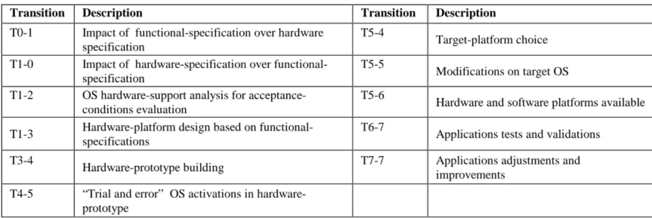
relationships which impact over other activities and steps. These relationships are called transitions. All transitions for a general ES development project are showed in Table 2. For instance, T0-1 means the transitions between steps 0 and 1. Figure 1 shows a graph which represents all transitions and steps obtained from the combination of Table 1 and Table 2.
Table 2. Transitions for Table 1
Transition Description Transition Description
T0-1 Impact of functional-specification over hardware specification
T5-4
Target-platform choice T1-0 Impact of hardware-specification over
functional-specification
T5-5
Modifications on target OS T1-2 OS hardware-support analysis for
acceptance-conditions evaluation
T5-6
Hardware and software platforms available T1-3 Hardware-platform design based on
functional-specifications
T6-7
Applications tests and validations T3-4
Hardware-prototype building T7-7 Applications adjustments and improvements
T4-5 “Trial and error” OS activations in hardware-prototype
It is noteworthy that all activities related with OS modifications are grouped in step N5’s transitions.
Figure 1. Transitions Graph and Steps
Modifications and adaptations on the project that occur in step N5 do not follow any specific method, because there is no method which reveals all required modifications. It is possible that some of these modifications may not be completed when they are necessary or they were simply forgotten, resulting an incomplete or inconsistent porting. In addition, there is no plan or schedule guiding the development simply because all the required modifications are unknown.
2. The Proposed Method
2.1. Method Overview
Table 3 shows the steps of the proposed method. They are enumerated from 0 to 4. Table 4 shows the transitions for these steps. Eventually, any of these steps can be re-run during the project execution.
Table 3. Five Steps of the Method
Step Description Step Description
N0 Evaluate Requirements through Decision Making Support (DM)
N3 Identify all source-code relationships N1 Identify Hardware elements without software support N4 Identify the source-code precedence N2 Identify all source-code to be modified
Table 4. Transitions for the Proposed Method
Transition Description
T0-0 Evaluate Requirements through decision making support T0-1 Impact of hardware-elements over software elements
T1-0 Reevaluation of hardware-elements impact over the decision making support T2-0 Impact of software-elements over project efforts, required for project accomplishment T0-2 Reevaluation of software-elements impact over the decision making support T2-1 Impact of software availability over hardware definition
T1-2 Impact of hardware availability over software definition T2-3 Impact of new software-elements over the dependency table T3-3 Recursive definition of software-dependencies
T3-4 Software-dependencies impact over precedence table actualization
T4-3 Precedence table impact over the dependency table – Creating precedence table
Figure 2 shows a graph representing all transitions and steps regarding the combination of Table 3 and Table 4. Steps N0, N1 and N2 are strongly connected and most critical issues are addressed in their transitions. A detailed description of all steps is presented in the next sections.
Figure 2. Five Steps Method Graph
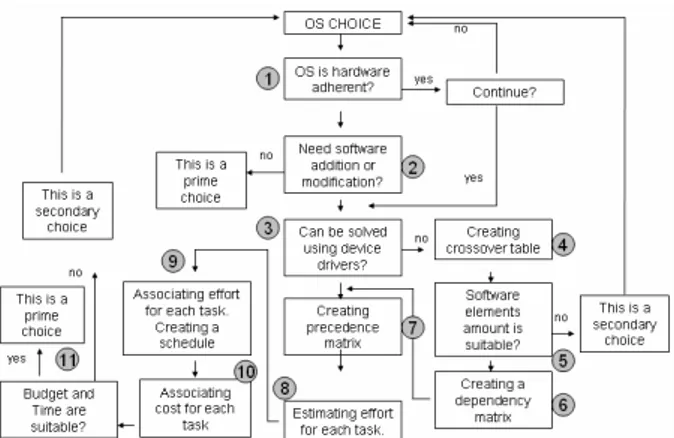
2.1.1. Step N0 – Evaluate Requirements through Decision Making Support
Figure 3. A Decision Making Model Applicable for ES
During project execution, DM can be adjusted in order to include new constraints. Of course, a suitable DM helps decreasing the effort placed on critical project’s phases [MARKO 2001]. The DM recursively uses other steps from the proposed method in order to provide the following information: if the target OS is suitable for the target hardware-platform; all hardware-elements lacking OS support; and all software-elements needing modifications for the new hardware-platform.
2.1.2. Step N1 – Identify Hardware-Elements without Software Support
Step N1 aims at identifying discrepancies in the target hardware platform for the chosen OS. The crossover table is the main result obtained from this step. If a different hardware element is present in the new hardware-platform, then a similar1 element must be selected. If the different hardware does not have any similar element supported in the chosen OS, the way to keep them working is by developing and using device drivers in order to provide OS supporting.
2.1.3. Step N2 – Identify all source-code to be modified
The precise definition of all source-code to be modified requires an extension of the crossover table, which takes place in steps N1 and N2. Note that only hardware-dependent source-code must be considered. The table extension is obtained by applying the read-and-search approach over the source-code.
2.1.4. Steps N3 and N4
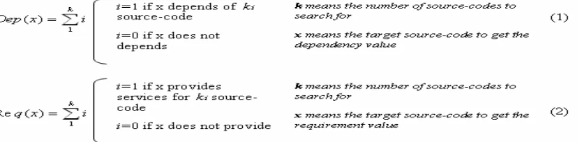
Three kinds of essential information are revealed through the crossover table: dependencies, requirements, and precedence. Dependency identifies the interconnection’s level of the source-code needing modification. Dependency’s level of a given source-code is obtained by adding all other source-codes from which the given source-code depends on. In general, the dependency computation is carried out as seen in (1) and the total of requirements as seen in (2).
The work needed for obtaining the information related to dependency and requirements of a source-code is a read-and-search job inside the OS source-codes. In order to perform this work, it is important to use some application. An application which gathers all steps of the proposed method and produces all required information, including crossover, was developed as a study case. However, tools as Code Count, CallTree, Free Code Graphing Project, and Source Navigator can be of great help [LSE 2006] [Navigator 2006]. Special care must be taken when solving cyclic references between source-codes since they could result in inadequate precedence classification. Such a problem occurs when a source-code file uses services implemented on another source-code.
Cyclic references must be resolved before the precedence between routines is computed. A strategy for solving this problem consists on using the Mock Object Pattern for creating temporary replacement routines [BROWN 2003]. In order to distribute the large information volume to be manipulated when porting an OS, a template/model for crossover-reference table called Dependency Matrix is proposed in the following subsection.
2.1.4.1. Step N3 – Creating a Dependency Matrix
Figure 4 depicts a dependency matrix, proposed for ES development. All source-code (subcomponents) and source-code families (components) that must be modified are placed in this matrix. For the purpose of clearness, the example shown in Figure 4 only presents the subcomponent’s level. Again, it is important to observe that only the source-code to be ported must be referenced. The matrix is filled by marking a component that depends on other component. In order to do that, each subcomponent (in a row) is inspected by marking all cells in that row containing a subcomponent (in a column) from which the given subcomponent depends on.
2.1.4.2. Step N4 – Creating a Precedence Matrix
A precedence matrix is obtained from information resulting from the processing of the dependency matrix. The Algorithm 1 (showed below) is part of the proposed method, and it classifies all routines held in the precedence matrix at the same time as it also solves cyclic reference issues.
This processing considers the dependencies and requirements computed using (1) and (2), respectively. Once the dep(s) and req(s) values are defined, all information needed in order to provide data required in steps 1, 2 and 3 of Algorithm 1 should be available.
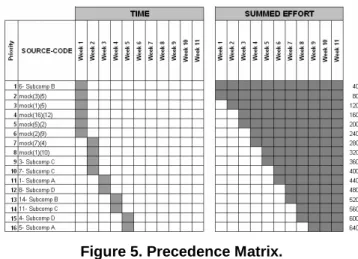
Figure 5 contains an example precedence matrix that is obtained by adding the effort needed for each adjustment to the result from Algorithm.
Figure 5. Precedence Matrix.
1. For each routine, all of dependencies of the routine are registered in a list. 2. Let DEP(i)= total of dependencies of the given routine
3. Let REQ(i)= total of requirements of the given routine 4. Make SUP(i) = 0
5. Make PEND(i) = DEP(i) 6. Make PRIORI(i) = 0 7. Make PRIORITY = 1
8. The dependency list is classified in ascending order based on PEND and in descending order based on REQ 9. For each routine pair R(i) and R(k) com PEND(i)>0, and cyclic dependence::
1. A mock routine named mock(i)(k) is created
2. Make REQ(mock(i)(k))=1: Make DEP(mock(i)(k))=0: Make SUP(mock(i)(k))=0 3. Add mock(i)(k) to the dependencies of R(i)
4. Remove R(k) from the dependencies of R(i)
10. Classify the dependence list in ascending order based on PEND and descending order based on REQ 11. For each routine R(i) such as PEND(i) = 0 and PRIORI(i) = 0, do:
1. Make PRIORI(i) = PRIORITY: PRIORITY = PRIORITY + 1 2. For each routine R(k) depending on R(i), do:
1. SUP(k)= SUP(k)+1 2. PEND(k)= DEP(k) – SUP(k) 12. Repeat step 10 until all routines are prioritized
13. Classify the dependency list in ascending order by PRIORI
Algorithm 1. Priority Computation and Cyclic Reference Removal.
3. Conclusions
projects. The proposed approach for obtaining dependencies between source-codes comprising the OS assures that all adjustments are considered.
The proposed algorithm also resolves problems arising from cyclic references, which are a real challenge in ES projects. The proposed table and matrix templates, that result from the algorithm application, allows for fast visual identification of the entire demanded work. It is important to observe that the precedence matrix provides not only information for determining the correct order of alterations, but also valuable management information for tracking the effort spent in the project.
The proposed method goes beyond its main goal of showing which adjustments must be done, and it also provides levels of control, priority and predictability over the ES development project in which porting of an OS is a fundamental task.
4. References
BOOCH, G, Object-oriented development. IEEE Transactions on Software Engineering. Vol. SE-12, no. 2, pp. 211-221., 1986 and "On Architecture," IEEE Software, vol. 23, no. 2, pp. 16-18, Mar/Apr, 2006.
BROWN, M. A, TAPOLESANYI, E., Mock Object Patterns, Version 1.2.3 – 2003. CAMPBELL, H. R., et al, CHOICES (Class Hierarchical Open Interface for Custom
Embedded Systems), Operating Systems Review, 21(3):9-17, 1987.
CARRO, L.; WAGNER, R. F., Sistemas Computacionais Embarcados, 2º capítulo, 2004.
FROHICH, A. A. M, Application-Oriented Operating Systems, Dissertação de mestrado Universidade Federal de Santa Catarina, 2001
LEE E.A., What’s Ahead for Embedded Software? - IEEE Computer, September 2000.
LSE, Libre Software Engineering – Disponível em:
http://libresoft.dat.escet.urjc.es/index.php? menu=Tools&Tools=Other- acessado em: 23/03/2006.
Navigator, The Source Navigator – An GPL IDE – Disponível em: http://sourcenav.sourceforge.net – acessado em: 10/10/2006.
PARNAS, D. L., On the Design and Development of Program Families, IEEE Vol SE-2 Nº 1, 1976.
POSADAS, H., et al, Single Source Design Environment for Embedded Systems Based on SystemC, Design Automation for Embedded System, 9, 293-312, 2004.
POLPETA, F. V., FROHICH. A. A. M, Um Método para a Geração de Sistemas Embutidos Orientados a Aplicação Baseados em SoCs, XXV Congresso SBC 3129- 2005.