ISSN 1517-7076 artigo e-11991, 2018
Corresponding Author : Andrés Glücksberg Received on: 01/08/2017 Accepted on: 25/09/2017
10.1590/S1517-707620180002.0328
Releasing systems for aerospace industry
based upon Shape Memory Alloys:
characterization of materials
for actuators
Andrés Glücksberg 1, Hugo Soul2, 3, Alejandro Yawny2, 3, 4
1 Instituto Balseiro (UNCuyo-CNEA), Av. Bustillo 9500, S. C. Bariloche, Río Negro, Argentina.
e-mail: andres.glucks@gmail.com
2 División Física de Metales, Centro Atómico Bariloche (CNEA), Av. Bustillo 9500, S. C. Bariloche, Río Negro,
Argen-tina.
3 CONICET (Consejo Nacional de Investigaciones Científicas y Técnicas), Buenos Aires, Buenos Aires, Argentina. 4 CNEA (Comisión Nacional de Energía Atómica), Buenos Aires, Buenos Aires, Argentina.
e-mail: hugo.soul@cab.cnea.gov.ar; yawny@cab.cnea.gov.ar
ABSTRACT
Releasing and deployment maneuvers carried out during space satellites launching are usually performed by utilizing pyrotechnics loads. However, it is considered convenient to replace this technique by others not requiring explosives (Non Explosive Actuators-NEA). This is mainly due to the necessity of reducing high-shock and vibrations induced levels, also avoiding the contamination of sensible instruments because of dust and gas release during explosion. In addition, the avoidance of risks associated with storage and manipulation of explosives and the possibility of performing device retesting prior to final mounting are desirable qualities. Among NEA devices, those exploiting the singular mechanical behavior of Shape Memory Alloys (SMA) have reached commercial maturity. In this study, the performance of a NEA device that uses the mechanical stress generated upon reverse transformation of a mechanically constrained SMA actuator (constrained recovery effect) to generate the controlled fracture of a notched bolt is analyzed. Firstly, the mechanical components of the system are described, and the main problems associated with its design are introduced. Then, the results of the experimental characterization performed on a NiTi SMA cylindrical tube actuator with 12.7 and 7.8 mm outer and inner diameter respectively, are presented. After an activation stage in which the cylinder is compressed to induce the martensitic phase (or re-orient the existing martensític phase), the temperature is raised while a constant displacement condition is imposed. For temperatures near 120 ºC, a loads increment of 35 kN (440 MPa) is obtained. The repetition of this loading-unloading-heating-cooling cycle does not generate any important deterioration in the material response.
Keywords: Constrained Recovery, SMA actuators, NiTi, Release systems.
1. INTRODUCTION
Martins. The improved design KQWNut, developed by Starsys Research Corporation, includes a ball bearing system which eliminates internal friction. A detailed description of these NEA devices can be found in ref. [4]. Another conceptual design of NEA corresponds to the Frangibolt system commercialized by TINI aerospace [5]. This design exploits the expansion of a SMA actuator to produce the fracture of an element producing the release, it is reusable and it is cheaper than separation nuts. Lower shock levels are reported and its preparation and reset result much simpler. As a drawback, it requires higher power and the response time are appreciably longer (20-50s). There is still a simpler approach adopted by Buban et al: they presented a design where a NiTi based SMA actuator produces its own fracture [6].
Releasing devices are engineered products of high added value, and although nowadays they are commercially available, the development of own designs is judged as a strategic aspect supporting the incipient Argentinean aerospace industry. This work is framed in a current line whose objective is the development of releasing systems based upon SMA. In this case, a device inspired in the Frangibolt design was adopted for its study, utilizing a NiTi SMA actuator as the kernel element. In the following sections, the SMAs behavior exploited in this kind of applications and their working principle of the studied system are described. Then, results of an experimental characterization of the NiTi alloy utilized for the actuator are reported and discussed. Experiments included the measurement of load and displacement levels attainable by the actuators, as their behavior stability and reproducibility upon repetition of operative cycles.
2. DESCRIPTION OF THE STUDIED SYSTEM
The functioning of the studied device is described in this section. Firstly, a brief introduction to SMA behavior is presented and then the studied device itself with its components is introduced.
2.1 Thermomechanical behavior of shape memory alloys
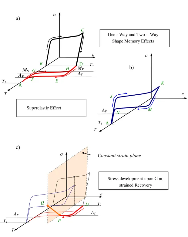
The particular behavior of shape memory alloys relies on the existence of a reversible martensitic transformation which can be induced by following either thermal or mechanical loading paths. Figs. 1a, 1 b and 1 c summarize the trajectories, denoted with green letters, associated with the forward and reverse transformation involved in the behaviors by which SMA can be technologically exploited [7]. Forward transformation (austenite to martensite) is characterized by its start and final temperatures MS and MF,
Figure 1: Thermomechanical behaviour of SMAs: Particular trajectories of SMAs on the --T space
Referring to Fig. 1a, the alloy can be transformed to a fully martenstic phase when it is cooled from its austenitic phase - point A at temperature T1 up to point B at temperature T2 below MF (martensitic finish).
Then, by applying a mechanical load up to point C an apparently irreversible strain arises upon unloading, point D, as it occurs with plastic yielding in convectional metals. But, when it is heated above a temperature AS (austenitic start) reverse transformation initiates and strains are recovered. Above a temperature AF
transformation is completed (point F). This cycle ABCDEFA constitutes the so called one-way shape memory effect. The applications concerning this effect are related to the capacity of a piece to recover its original shape after damage involving inelastic deformation. By means of special training procedures it is possible for the material to “remember” not only the austenitic phase shape, but also another prescribed shape for martensitic phase. Now, it is possible to switch between them by changing the temperatures trough the
T Superelastic Effect
B
MS
AF
A
C
D
F E
T
T1
T2
MF
AS H G
a)
A
J
K
M N
T1
AF
One - Way and Two - Way Shape Memory Effects
b)
AF
D
T
Constant strain plane
P Q
T1
T2
AS
c)
cycle as depicted by the cyclic trajectory AGHDEFA. This effect, known as the two-way shape memory effect is on the basis of the uses of SMA as thermal actuators [8, 9]. Fig. 1 b explains the superelastic effect, which arises when transformation to martensite is induced by mechanical loading from point A (temperature above AF). When a critical stress is reached in point J the material starts to transform, being strained with a much lower stiffness until transformation is completed in point K. Reverse transformation has place during unloading, when another critical stress (lower than the prior) is reached at point M. Reverse transformation continues also with a low modulus up to point N, from which elastic unloading continues. SMAs following a superelastic cycle as AJKMNA exhibit high recoverable maximum strains (up to 8%). This capacity provides superelastic slender elements of extraordinary kink resistance capacity [10]. Biocompatible SMAs, as the NiTi based group find an extensive use in medical applications as stents, catheters and orthodontics devices [11, 12]. A novel application has been recently proposed for NiTi superelastic wires. In this case, the reverse transformation load, exerted along an extended displacement range is utilized for the correction of osseous malformations [13, 14]. Non medical applications are related with vibration control of mechanical structures due the dissipative capacity associated with the - hysteresis [15,16]. A last particular behavior, described in Fig 1.c, takes place when a constraint is applied avoiding the austenitic shape of the alloy to be freely recovered upon heating, for example at point P. The alloy reacts generating a load against the constraint. If heating is performed at constant strain, the state of the alloy at temperature T1 corresponds to point Q. The
stress generated upon constrained recovery is the consequence of the linear dependency of the transformation stresses with temperature due the Clasius - Clapeyron relationship [17]. The capacity of load generation upon constrained recovery was proposed for several applications. In SMA mechanic seals [18], the load generated upon the recovery a hollow cylinder constrained in the radial direction is exploited to set strong coupling in piping systems. Bars and cables of NiTi SMAs have been studied for the compensation of the thermal stresses variation generated upon temperature changes in structures stabilized by metallic tendons [19, 20]. In the following sections it is explained how this thermomechanical trajectory of SMAs can be exploited in releasing systems.
2.2 Releasing system with SMA actuator
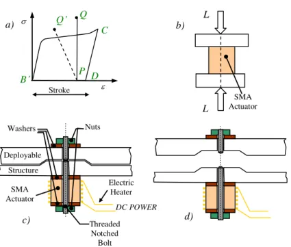
For the sake of clarity, a description of the thermomechanical path followed by a SMA utilized as a load actuator was repeated separately in Fig. 2 a. The material states are indicated with the same letters than in Fig. 1. Figs. 2 b-d depicts the arrangement of the device here studied. The actuator, in this case a thick walled cylinder, must be initially at temperature below As. In this situation the material can be in fully austenitic
phase, fully martensitic phase or partial austenitic/martensitic phase, depending upon the previous history. Then, it is uniaxially compressed in order to induce fully martenstic phase by stress up to point C, or to re – orient the already existing martensite.
When load is relaxed, the actuator remains strained at point D. The displacement associated with this stress-free strain is referred as the actuator stroke. This procedure, previous to the assembly mounting is referred as the actuatoractivation. Now the actuator is introduced as a part of the mechanical assembly as depicted in Fig. 2 c. When deployment is required, the actuator is heated by means of the electric heater, and the load of the mechanical assembly raises (point Q) up to produce the fracture of a union element (Fig. 2 c). It is worth to remark that the constraint imposed to the actuator presents a finite stiffness, and a real path would look like point P to point Q’. Excessive flexibility of the elements composing the assembly could cause the actuator stroke capacity to be exhausted and fail in fracturing the bolt. Therefore, the success operation depends not only on the load capacity of the actuator but also on the total displacement required for the bolt to be fractured. The threaded bolt utilized as the union element has a circular notch mechanized in order to limit its ductility by promoting a triaxial stress state upon loading. Nuts and washers must have high stiffness and hardness for stroke capacity saving. Regarding the SMA actuator, it is required that As to be
Figure 2: Functioning principle of the SMA actuator. a) path corresponding to the activation procedure, for which the
SMA actuator is transformed to martensite with the associated displacement stroke by uniaxial compression b) SMA actuator activation, compressed by the load L. c) Mechanical assembly with the SMA actuator. d) The assembly
de-ployed once the bolt was fractured by the SMA actuator.
3. MATERIALS, METHODS AND EQUIPMENTS
SMA Actuators were extracted from a NiTi hollow bar of composition 50.8 % Ni at, with 12.7 mm (80 mm2 of section) and 7.9 mm of external and inner diameters respectively. The bar was received in a cold worked condition (HRC ≈ 60). Specimens of 20 mm length were cut for the actuators with a diamond disc. Nuts and washers were specially mechanized with AISI 1040 steel and surface hardened by carburizing. The electrical heaters were made with manganina cable of diameter 0.25 mm and a resistance of 48 /cm covered by a glass fiber vain. Total resistances were 10 and 15 ohms depending upon length. Characterization and activation of the actuators were performed in a universal servo-hydraulic machine MTS 810, with a cell load MTS with capacity of 100 kN. Measurement of load in the assembly once mounted was performed by an annular load cell Futek LTH 350 with 9 kN of capacity.
Temperatures were measured by a type K thermocouple. Electrical current for actuator heating was provided by a home made DC unit of 30 V and 5 A of maximum capacity. NiTi specimens were subjected to several annealing treatments in order to achieve a behavior compatible with the application in conventional electric furnaces. In Fig 3 a there was included images of the NiTi bar as received. Fig 3 b is an image of two of the utilized actuators, and Fig 3 c illustrates the experimental setup for the compression tests of the actuator, with the coiled heater and a thermocouple adhered.
Stroke
B’
C
D P
Q
Q’
Electric Heater Deployable
Structure
Washers Nuts
Threaded Notched Bolt Bolt SMA
Actuator
L
L
SMA Actuator
DC POWER
a) b)
Figure 3: NiTi SMA utilized for the fabrication of the actuators. a) Bar in its received condition. b) Two NiTi hubs sub-jected to different thermal treatments. c) NiTi hub with the coiled electric heater ready for a compression test for the acti-vation procedure in the MTS 810 machine.
4. RESULTS AND DISCUSSION
Unless other values are explicitly mentioned, compression tests were done by controlling displacement at a velocity of 0.1 mm/min at room temperature of 22 ºC. Temperature of the actuators was registered by sticking a K type thermocouple on the NiTi nucleus.
4.1 Activation procedures and constrained response for hubs with different heat treatments
Heat treatments are carried out to SMA with several aims. Firstly, the phase presenting the transformation must be stabilized. But also, in the case of NiTi SMAs, annealing treatments are needed for improving the poor mechanical properties. Basically, this is achieved by recovery of cold worked microstructure and the precipitation of Ni4Ti3 particles [21]. Therefore, precipitate volume fraction depletes matrix from Ni content. This has consequences on the transformation temperatures values, since they drop sharply with Ni content around 50 % at. As long as annealing duration and temperatures are increased it is expected that Ni content in the matrix to diminish and therefore, transformation temperatures to be increased (or transformation stresses to be decreased). While the effect of annealing parameters on the recovery response of constrained NiTi wires has been widely investigated (see e. g. ref. [22, 23]), there are no systematic studies for other actuators geometries. Figs. 4 include the load - displacement curves obtained from the activation procedure performed to the NiTi actuators subjected to different thermal treatments. Fig. 4a corresponds to the material in its received condition. It was compressed up to near 80 kN and no evidence of martenstic transformation was observed. Inelastic deformation is associated with plastic strains shared between the material and the compression plates.
The first heat treatment tested was a 30 min-450ºC annealing, being obtained the curve of Fig. 4 b. It can be observed that reverse transformation initiates around 12200 N and a superelastic cycle is almost completed upon unloading. This means that Af is nearly above room temperature, just a few martensite
fraction remains at the end, and small stroke and load capacity are expected. The second tested heat treatment was set in 60 min-450 ºC, resulting in the curve of Fig. 4 c. In comparison with the prior test, stress levels were reduced and a stroke around 0.4 mm was obtained upon unloading. Then, the actuator was heated up to 90 ºC keeping displacement fix (the corresponding curve is included in the Figure), and the load rose up to 21287 N, high enough to overcome the strength of a M6 threaded bolt with 1200 MPa of UTS.
0.0 0.2 0.4 0.6 0.8 1.0 1.2 1.4 0 10 20 30 40 50 60 70
80 a)
L o a d [ kN] Displacement [mm]
1st Cycle
2nd Cycle
3rd Cycle
9317 N 118 MPa 55137 N 699 MPa 77993 N 988 MPa
0.0 0.2 0.4 0.6 0.8 1.0 1.2 1.4 0 10 20 30 40 50 b)
12220 N 160 MPa
1.039 mm 3.88 %
0.341 mm
35917 N 470 MPa
1.159 mm 4.54 %
25208 N 330 MPa
0.704 mm 2.01 %
L o a d [k N ] Displacement [mm] HT: 450 ºC - 30 min
0.0 0.2 0.4 0.6 0.8 1.0 1.2
0 10 20 30 40
50 HT: 450 ºC - 60 min c)
Lo ad [kN] Displacement [mm] 21287 N 270 MPa 0,38mm 24285 N 308 MPa 32562 N 412 MPa 8372 N 106 MPa
0.0 0.2 0.4 0.6 0.8 1.0 1.2
0 5 10 15 20 25 30 35
40 d)
115 MPa 379 MPa 299 MPa L o a d [ kN] Displacement [mm] 23896 N 9160 N 30294 N HT: 550°C - 10 min
0.0 0.2 0.4 0.6 0.8 1.0
0 5 10 15 20 25
30 e)
64 MPa 329 MPa 260 MPa L o a d [ kN] Displacement [mm] 0,4 mm 20814 N 26287 N 5153 N HT: 500°C - 120 min
0.0 0.2 0.4 0.6 0.8 1.0
0 5 10 15 20 25 30 35 f) 25570 N 321 MPa 371 MPa 29700 N 239 MPa 19080 N L o a d [kN] Displacement [mm] HT: 450 °C 60 min + 500°C 120 min
Figure 4: Load - Displacement curves corresponding to the activation procedure of NiTi actuators with different heat treatments. Fig 4 c and 4 f includes also the curve associated with the load generation upon constrained heating.
4.2 Dependence of the maximum load level with initial condition
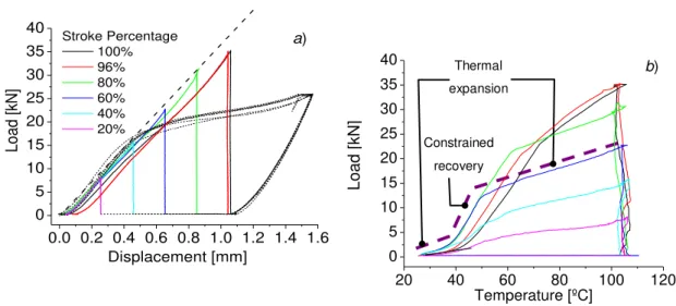
Load values reached upon constrained heating showed in Figs. 4 c and 4 f were obtained by fixing the displacement at the maximum stroke capacity of the actuators once activation finished. This state can be roughly assigned to a fully martensitic state. But as it is discussed in Fig 2 a, due finite stiffness of the assembly, some stroke capacity would be “consumed” upon load actuation. Therefore, it is worth to measure the load capacity reached for different stroke positions. With this aim, an experiment with a 40 mm length actuator with a heat treatment of 500º C – 120min was performed. It consisted on an activation procedure followed by an unconstrained heating for which the stroke is recovered (path DHEFA in Fig.1).
Once a predefined position is reached, a fix displacement condition is imposed, while heating continues up to 110 ºC. With this method, the loads developed for six different initial positions (indicated as stroke percentages) have been measured. As it can be observed in Fig 5 a, the maximum attainable loads seem to be roughly determined by the initial stiffness line prolongation (see ref [24] for an explanation). Curves of Fig. 5 b correspond to a load - temperature representation of the results. As it is schematized with the dashed line in the Fig. 5 b, each one of these curves can be roughly described by three segments. A first segment for which the actuator is heated up to reverse transformation initiates.
0.0 0.2 0.4 0.6 0.8 1.0 1.2 1.4 1.6 0 5 10 15 20 25 30 35 40 a) Stroke Percentage 100% 96% 80% 60% 40% 20% L o a d [ kN] Displacement [mm]
Figure 5: Load levels developed during heating by constraining actuator at different stroke positions: a)
Load - Displacement representation of the measurements. b) Loads developed as function of the temperature measured by a thermocouple adhered in the actuator external surface.
4.3 Stability and reproducibility of SMA behavior upon operative cycling
One of the requirements for the releasing devices is the reproducibility of their operative cycle. That means actuators needs to be activated and then the required loads to be generated at least a determined number of times. This characteristic allows testing devices before satellite launching. Therefore, the stability in the material behavior upon the cycle repetition results an important aspect to be verified experimentally. It is known that SMA can show important behavior deterioration upon mechanical or thermal cycling, which is known as functional fatigue [25, 26]. With the aim of evaluating cyclic behavior of the SMA actuator, several experiments were carried out. Fig. 6 a corresponds to five consecutive activation procedures performed with a 20 mm length actuator. Once activation has finished, displacements were recovered upon heating. There are practically no changes in the load - displacement curves for the five cycles. This contrasts with the functional fatigue registered by tension cycling of superelastic NiTi wires, for which a remarkable drop in transformation stresses arises during the first hundred of cycles. In other experiment, depicted in Fig. 6 b, the activation followed by heating with constrained displacement, and posterior cooling up to ambient temperature was repeated four times for the same actuator. Obtained cycles show that the load - displacement curves are shifted to the right upon cycling. This resembles the ratcheting phenomena in low cycle fatigue and indicates that some irreversible deformation accumulates upon cycling. Despite this evolution, load levels reached during constrained heating after activations keep above 30 kN, i. e. no deterioration on load capacity was registered upon cycling.
Figure 6: SMA actuator behavior upon operative cycling. a) Repetition of five consecutive activation procedures. b) Repetition of four consecutive activation + constrained heating cycles.
Thermal
expansion
Constrained
recovery
20 40 60 80 100 120
0 5 10 15 20 25 30 35 40 b) Fo rce [ kN] Temperature [ºC] L o a d [ kN]
0.0 0.2 0.4 0.6 0.8 1.0
0 5 10 15 20 25 30
35 a)
L o a d [ kN] Displacement [mm] 5 cycles
Upper Limit: 30 kN
-0.2 0.0 0.2 0.4 0.6 0.8 1.0
0 5 10 15 20 25 30 35
40 b)
4.4 High speed loading during activation procedure
Up to this point, experiments were performed at a displacement velocity of 0.1 mm/min. A complete activation procedure with an actuator of 20 mm length requires around 15 min. This velocity was selected in order to achieve near quasi static experimental conditions. But such a time demanding procedure could turn impractical its implementation. Therefore, an activation procedure with loading and unloading displacement rates of 10 mm/min was also considered. This velocity turn conditions more similar to those arising with the use of a conventional hydraulic press. A 20 mm length actuator was compressed at 10 mm/min up to a load magnitude of 30 kN. This load level was hold during 120 s. As it can be observed in Fig. 7, during this holding period the displacement increases up to an equilibrium value approximately coincident with the reached at 0.1 mm/min. It is assumed that the SMA has reached an equilibrium state there. Then, load relaxing was also performed at 10 mm/min, resulting in a stroke of 0.5 mm, higher than the achieved at 0.1 mm/min. Further, the actuator was heated under a constrained displacement condition reaching a load of 42.89 kN, even above the values obtained for the low velocity tests.
0.0 0.2 0.4 0.6 0.8 1.0 1.2
0 10 20 30 40 50
L
o
a
d
[
kN]
Displacement [mm] 10mm/min
0.1mm/min
30000 N 42890 N
32471 N
Figure 7: Fast activation procedure. The activation using 10 mm/min instead of 0.1 mm/min produces a higher load level
upon constrained heating.
4.5 Release testing of SMA actuator + notched bolt assembly
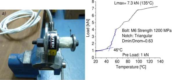
Finally, an arrangement emulating the mechanical assembly to be released by the actuator was mounted and tested with the aim to verify the feasibility of the proposed device. The image of Fig 8 a shows the experimental set up. A steel threaded bolt M6 with a triangular notch was utilized as the union element. The transverse section in the notch was reduced up to a 63% of the nominal area. Three reinforced washers and a reinforced nut were introduced in the assembly. An annular load cell, with 9 kN of capacity was disposed as shown in the photograph in order to measure the load generated by the actuator upon heating. Fig. 8 b illustrates the evolution of the load measured with the annular load cell with the actuator temperature. An initial pre-load of 1 kN was applied. Heat was introduced by employing an electrical power of 10 W (10V@1A).
20 40 60 80 100 120 140 0
1 2 3 4 5 6 7 8
L
o
a
d
[
kN]
Temperature [ºC] 46°C
Lmax= 7.3 kN (135°C)
Pre Load: 1 kN
Bolt: M6 Strength 1200 MPa Notch: Triangular
Dmin/Dnom=0.63
Figure 8: Release testing of the SMA actuator in a mechanical assembly. a) Experimental set up. b) Developed load as a function of the actuator temperature
Additional experiments were performed applying higher pre-load values. Due to that the load cell maximum capacity was 9 kN, it was removed from the arrangement in these tests. Before, a calibration of the load in the assembly and the applied adjustment torque was performed. Therefore, a torque of 10 Nm, corresponding to a pre load between 6 and 7 kN was applied. Then the actuator was heated again with 10 W of electrical power, being the bolt fractured after 40 s around 80 ºC. The details of this experiments and the torque-pre load calibration can be found in ref [12]. A movie clip registering the assembly, the heating and the bolt fracture was submitted as a supplementary material of this article.
5. CONCLUSIONS
The experimental work carried out during this first stage of the research allowed to verify the feasibility of utilizing actuators made with SMA. In particular, actuators made from a hollow bar of NiTi SMA previously subjected to suitable thermal treatments. It was found that with a heat treatment of 450 ºC / 60 min plus 500 ºC / 120 min the actuator exhibited a suitable behavior being possible to be activated at ambient temperature and be kept in martensitic phase. The load levels developed by the actuators in their maximum stroke position upon constrained heating overcome 30 kN of load. A rather linear dependency of the maximum developed load level with the stroke position was measured. In separated experiments it was demonstrated that mechanical and thermal cycling does not affect the actuator load capacity. Additionally, it was demonstrated that using high velocities during the activation procedures, with a pause between loading and relaxing give place to even higher loads developed upon constrained recovery. Tests performed with the actuator/bolt assembly allowed verify the possibility of exploiting the load generated upon constrained recovery of the SMA actuator pushing against a finite stiffness element. Further work must include measurement of additional variables concerning the releasing operation as the attained shock levels, actuating temperatures and times, etc.
6. ACKNOWLEDGMENTS
This work includes partially research performed in the frame of a final project for the degree in the mechanical engineering career of the Instituto Balseiro (CNEA-UNCuyo). It was developed mainly in the Physics of Metals Division of the Centro Atómico Bariloche (CNEA). Financial support of CNEA and CONICET is acknowledged. Technical assisting and advice of Dr. Iván Korin, from the Structures Department of INVAP SE is specially acknowledged.
7. BIBLIOGRAPHY
[1] FOSNESS, E. R., BUCKLEY, S. J., GAMMILL, W. F,, Deployment and release devices efforts at the air force research laboratory space vehicles directorate, Report number A2001-4601, AIAA, 2001.
[2] LUCY, M. H., HARDY, R. C., KIST Jr, E. H., et al, Report on alternative devices to pyrotechnics on spacecraft, Report number 19970711-127, NASA Langley Research Center, Hampton, VA, 1996.
[3] BUSCH, J. D., PURDY, W. E., JOHNSON, A. D., “Development of a non-explosive research device for aerospace applications, Proceedings of the 26th Aerospace Mechanism Symposium”, NASA Goddard Space Flight Center, Greenbelt, Maryland May 13-15, 1992.
[4] YOO, Y., JEONG, J. W., LIM, J. K., et al, “Development of a non-explosive release actuator using shape memory alloy wire”, Review of scientific instruments, v. 84, paper nro 015005, 2013.
[5] TINIAEROSPACE. Disponível em: http://www.tiniaerospace.com/fbconcept.html.
[6] BUBAN, D. M., FRANTZISKONIS, G. N., “Shape memory alloy fracture as a deployment actuator”, Smart Materials and Structures, v.22, paper n. 115034, 2013.
[7] DUERIG, T. W., MELTON, K. N., STÖCKE, D., et al., Engineerig Aspects of Shape Memory Alloys, 1er edition, Londres, Butterworth-Hinemann,1990.
[8] ENGEBERG E., DILIBAL S., VATANI M., et al, “Anthropomorphic finger antagonistically actuated by SMA plates”,Bioinspiration and biomimetics, v.5, n. 10, pp.1-15., 2015.
[9] ELAHINIA M., Shape memory alloy actuators: design, fabrication, and experimental evaluation, John Wiley & Sons, Inc., Hoboken, NJ, USA, 2015.
[10] CHAN Y., CHENG S., “Angioplasty and stenting of distal anastomotic stenosis of femoropopliteal bypass graft using helical interwoven nitinol stents”,Inernational Journal of Angiology, v. 25, n.5, e25 - e58, 2016.
[11] JANI, J. M., LEARY, M., A. SUBIC, et al, “A review of shape memory alloy research, application and opportunities”, Materials and Design, v. 56, pp.1078–1113, 2014.
[12] LIANG T, CHANG L, WEI-XUAN L, et al, “Super-elastic behavior analysis of shape memory alloy vascular stent”, In: Advances in Engineering Plasticity and its Application XIII, v. 725, n.2, pp. 405 – 409, 2017.
[13] YAWNY A. SADE M., BERTOLINO G., et al, “Caracterización de implantes de NiTi para la corrección de deficiencias óseas”, In: Congreso SAM/CONAMET 2016, Córdoba, Argentina, pp. 681 – 682, 2016.
[14] KORTEN M., Desarrollo de dispositivos ortopédicos basados en el Efecto Superelástico para el tratamiento de distintas deficiencias óseas, Proyecto Integrador Ingeniería Mecánica, Instituto Balseiro-Universidad Nacional de Cuyo, San Carlos de Bariloche, 2015.
[15] OZBULUT, O., HURLEBAUS, S., DESROCHES, R., “Seismic response control using shape memory
alloys: a review”, Journal of Intelligent Materials and Structures, v. 22, 1531–1549, 2011.
[16] SOUL H., YAWNY A., “Self-centering and damping capabilities of a tension-compression device equipped with superelastic NiTi wires”, Smart Materials and Structures, v. 24, 2015.
[17] CARDONE, D., DOLCE, M., “SMA-based tension control block for metallic tendons”, International Journal of Mechanical Sciences, v. 51, pp.159–165, 2009.
[18] XIAOFENG L., GANG L., LUWEI L., et al, “Effect of Aging Treatment on the Compressibility and Recovery of NiTi Shape Memory Alloys as Static Seals”, Journal of Materials Engineering and Performance, v. 26, n.7, pp. 3025 – 3033, 2017.
[19] CARDONE D., DOLCE M., “SMA-based tension control block for metallic tendons”, International Journal of Mechanical Sciences, v. 51, pp. 159–165, 2009.
[20] CARDONE D., GESUALDI G., NIGRO D., “Improving the thermal behavior of steel tendons by shape memory alloys”, IABSE Symposium Report, v. 101, n.1, pp. 1-8, 2013.
[21] OTSUKA, K., REN, X., “Physical Metallurgy of Ti–Ni-based Shape Memory Alloys”, Progress in Materials Science, v. 50, pp.511–678, 2005.
[22] YAN X,, GE Y., VAN HUMBEECK J., “Influence of different thermo-mechanical cycling routes on recovery stresses of annealed niti wires”, Journal of Materials Engineering and Performance, v. 25, pp. 267-273, 2015.
[25] YAWNY A, SADE M., EGGELER G. “Pseudoelastic cycling of ultra-fine-grained NiTi shape-memory wires”, Zeitschrift für Metallkunde, v. 96, n.6, pp. 608-618, 2005.
[26] OLBRICHT J., YAWNY A., CONDÓ A., et al., “The influence of temperature on the evolution of functional properties during pseudoelastic cycling of ultra fine grained NiTi”, Materials Science and Engineering A, v. 481–482, pp. 142–145, 2008.