A Sensor Cloud
Enabler for the Factory
of the Future
Ana Sofia Alves de Oliveira Ferreira
Mestrado Integrado em Engenharia de Redes e Sistemas Informáticos
Departamento de Ciências de Computadores 2015
Orientador
Gil Manuel Magalhães de Andrade Gonçalves, Assistente Convidado, Grupo de Engenharia da Decisão e Controlo ISR - FEUP
Coorientador
Todas as correções determinadas pelo júri, e só essas, foram efetuadas.
O Presidente do Júri,
Agradecimentos
Primeiro de tudo quero agradecer ao meu coorientador, Luis Neto por todo o
conhec-imento que me passou e toda a paciˆencia que teve para o fazer.
Agrade¸co ao meu orientador Gil Gon¸calves pelo apoio e oportunidade que me deu
para realizar este est´agio no SysTec-FoF.
A toda a equipa do SysTec-FoF pelos bons momentos passados e pela entreajuda que
me permitiu aprender mais que aquilo que contava. Um especial obrigada ao Jo˜ao,
Susana e Gra¸ca por me ajudarem muito na escrita deste documento.
Um forte obrigado a toda a minha fam´ılia, aos presentes e aos ausentes, que sempre me apoiaram em tudo o que fiz e me conduziram no caminho certo.
Agrade¸co a todos os colegas do curso, porque estamos juntos e de sa´ude t˜ao bem.
Por ´ultimo, deixo um obrigado ao Joaquim Silva por todo o trabalho e horas de
frustra¸c˜ao que partilhamos e tamb´em pelos momentos de relax que aconteceram, e um
obrigado ao F´abio Vilar por todas as vezes que me raptou e me fez ver que havia mais
vida al´em da tese!
Resumo
Trabalhos tˆem sido desenvolvido para reduzir no cen´ario da produ¸c˜ao em massa,
como ´e o caso da ind´ustria, o desperd´ıcio e a fraca gest˜ao de mat´erias primas e recursos,
que afetam a eficiˆencia e o ramp-up-time. Estes trabalhos levaram ao desenvolvimento
de uma solu¸c˜ao integrada para sistemas de monitoriza¸c˜ao e/ou controlo de linhas de
produ¸c˜ao, o SmartComponent.
O trabalho desenvolvido neste projecto tem como objetivo continuar o
desen-volvimento do SmartComponent na gest˜ao de todos os sensores nesses sistemas e
conectar a WSN com a tecnologia FIWARE. Sendo um projecto de c´odigo livre, o
FIWARE, que se baseia em Generic Enablers (GE) divididos por diversas categorias,
fornece um vasto leque de fun¸c˜oes que podem ser utilizadas numa infinidade de ´areas.
Al´em disto, no contexto deste trabalho, o FIWARE foi incorporado num contexto
privado por quest˜oes de privacidade e confidencialidade, fatores estes, de grande
importantes no sector industrial pois s˜ao a maior defesa contra a competi¸c˜ao.
Os testes efetuados na vers˜ao desenvolvida neste trabalho demonstram uma
solu¸c˜ao melhorada da referida anteriormente, o SmartComponent. Neste trabalho,
demonstramos que esta ´e uma melhor solu¸c˜ao para o sistema, sendo menos complexa
que a solu¸c˜ao anterior, verificando-se em simultaneo uma melhoria no consumo de
mem´oria, que resultou num sistema mais eficiente e escal´avel.
Por ´ultimo, este trabalho foi integrado no contexto de um projeto Europeu
-SelSus - que ´e co-financiado pelo programa EU’s Seventh Framework Programme.
Abstract
Previous work has been done in order to reduce in a scenario of mass produc-tion, such as the industrial case, the waste and poor management of raw materials and resources which affect efficiency and ramp-up-time. Such work has developed a solution integrated in a system of monitoring and/or controlling production lines, the SmartComponent.
This work aims to further develop the SmartComponent in the management of all the sensor devices present in such system and connect WSN with FIWARE technology. As an open-source technology, FIWARE, which is based on Generic Enablers (GE) each divided in various categories, provides a vast sample of functions which can be used in a multiplicity of areas.
Furthermore, in the scope of this dissertation, FIWARE was incorporated in a private context due of its consequential advantage of confidentiality, so important to the industrial sector in order to stand out against the competition.
The test results showed an improved solution from the previously mentioned work, the SmartComponent. It was demonstrated that it is a better solution in the system, less complex than the previous one and with improved memory usage resulting in a more efficient system.
Finally, this work was integrated in the scope of the European project - SelSus - co-founded by EU’s Seventh Framework Programme.
“See things from the boy’s point of view.”
Contents
Resumo 5 Abstract 6 List of Figures 10 1 Introduction 13 1.1 Motivation . . . 14 1.2 Problem definition . . . 141.3 Contribution to the problem . . . 16
1.4 Organization . . . 16
2 State of the art 18 2.1 Architecture Context . . . 18
2.2 European Industrial project . . . 20
2.2.1 SELSUS . . . 20 2.2.2 I-RAMP3 . . . 21 2.2.3 Reborn . . . 22 2.3 Technology . . . 23 2.3.1 UPnP . . . 23 2.3.2 FI-PPP . . . 24
2.3.2.1 FIWARE . . . 25
2.3.2.2 FIWARE-LAB . . . 28
2.3.2.3 FITMAN . . . 28
2.3.3 Other Cloud provider approaches . . . 29
2.3.3.1 Virtual Fort Knox . . . 30
2.3.4 Challenges of industrial WSN . . . 31
2.3.5 Challenges of Sensor-Cloud . . . 32
3 Background & methodology 33 3.1 Existing SmartComponent implementation . . . 33
3.1.1 Technology Limitations . . . 34
3.2 Development Methodology . . . 35
3.2.1 A REST-based Approach . . . 37
3.2.2 Context Broker . . . 38
4 Implementation 39 4.1 Porting the SmartComponent to the FIWARE . . . 39
4.1.1 Instance on the FIWARE-lab . . . 41
4.2 Local Implementation of FIWARE infrastructure . . . 43
4.2.1 FIWARE Installation ToolBox . . . 43
4.2.2 FUEL and OpenStack . . . 45
4.2.3 Installation process . . . 46
5 SmartComponent test-bed 49 5.1 Infrastructure . . . 50
5.1.1 Components of the Network . . . 50
5.1.2 Shop-Floor . . . 51 9
5.2 Test case . . . 51
6 Test results and analysis 53 6.1 Performance criterion . . . 53 6.1.1 Complexity . . . 53 6.1.2 Memory concerns . . . 54 6.1.3 Efficiency . . . 54 6.2 Test Results . . . 54 6.2.1 Complexity Comparison . . . 55 6.2.2 Memory analysis . . . 55 6.2.3 Efficiency Comparison . . . 57 6.3 Discussion . . . 59 7 Conclusion 61 7.1 Future work . . . 62 Appendices 64 A Abbreviations 65 References 67
List of Figures
2.1 General Sensor-cloud architecture . . . 19
2.2 FI-PPP Programme Architecture [10] . . . 25
3.1 Physical Architecture Monitoring Production Line [8] . . . 33
3.2 Physical Architecture . . . 36
4.1 Communication General States . . . 40
4.2 Instance Settings . . . 42
4.3 Network Rules . . . 42
4.4 Fuel Package . . . 44
4.5 Network Topology for Fuel and OpenStack projects . . . 45
4.6 Web-interface of the FUEL server . . . 47
4.7 Settings of OpenStack Environment . . . 48
4.8 OpenStack environment interface . . . 48
5.1 Test Case System Operation . . . 52
6.1 Classes needed on UPnP SmartComponent . . . 55
6.2 Classes needed on FIWARE SmartComponent . . . 55
6.3 Relation Instance vs Memory [8] . . . 56
6.5 Capture of Subscribe Stream . . . 57
6.6 Capture of Send file UPnP Stream . . . 58
6.7 Capture of Send file FIWARE Stream . . . 58
Chapter 1
Introduction
Since 1913, when Henry Ford installed the first assembly line for the mass production of an entire auto-mobile, the manufacturing industry did not stop trying to improve in every way possible the process involved in the assembling of a product. Throughout the years new machines where invented, new procedures and new mate-rials where discovered. Now a new era has, arrived, the Internet of Things Age [14], in which everyday objects become equipped with sensing and actuation capabilities, introducing new requirements concerning the interoperability of embedded software systems.
This new Age brought to the manufacturing world a room to evolve and become more profitable than ever before. The use of sensors allowed a way of controlling and managing the machines on the shop floor. Reducing the need to have people working around the machines makes the process less vulnerable to errors, less prone to misconfigurations and malfunctioning machines. The sensors came as an important asset to the organization on managing the shop-floor.
However, and as a consequence, manufacturers are facing new challenges unlike any in the past. The world is moving faster and is more connected than ever before. In addition, a turbulent world economy, explosive growth in consumer technology, and rapidly changing and sometimes unpredictable consumer purchasing behaviors
all bring both opportunity and risk. For these reasons, there has never been a
more important time for manufacturers to invest in the next generation of industrial automation solutions.
The appearance of sensor-cloud is now the future path for the manufacture in-dustry. The advantages of this technology are immense from accessibility to scalability
where an organization in an early stage can have a small size sensor network and then grow this network with no concerns. The large routing architecture of cloud means that organization can add extra services from cloud computing vendors without the need to invest heavily for this additional hardware [19].
1.1
Motivation
The present work was motivated by the concerns for the European economy, and its efficient evolution can mean the reduction of important costs. In order to help in the European economy sustainability, we focus on helping the manufacturing industry, through the SelSus project [28], to achieve their goals in developing innovative concepts for more flexible and maintainable shop-floor.
The present work was developed in the industry context, which has many areas to explore, is also a differentiating factor. This is important, as the majority of the greatest technological developments may occur in the industrial environment.
This project is also very challenging due to the fact of its main goals are related with the interaction of two hot topics in the of the moment: Internet of things and Cloud Computing, being this way a cutting edge technology.
The fact that SelSus Project and consequently the present work can be imple-mented/used in European zone, in which Portugal being the country that supports the developed work belongs, is also a reason to feel motivated, once this work can contribute for the sustainable grow of this country.
1.2
Problem definition
The production lines require permanent monitoring in order to increase the profitability of the components used to produce a certain product. To achieve this intensive monitoring control, sensing devices are used to generate important and useful data that will allow a verification of malfunctions in machines or other deficiencies. These sensors create a Wireless Sensor Network(WSN) with all the control sensing devices incorporated on the machines or distributed throughout the shop-floor, with all the provided information of production line current status.
The generated data must then be treated to provide an useful and organized 14
knowledge of the production line. To treat the data, computational methods are used to provide a higher degree of intelligence in order to ensure the quality of the information, and provide a window of trust between the “administrator” and the WSN. A non-trivial problem arises: the development and integration of different algo-rithms of data reduction and validation, for further analysis, require strong changes in the monitoring system during runtime. It is important not only to discover anomalies on the production line but also be able to anticipate them. Hence, it is mandatory to integrate a new monitoring system to evaluate the changes on the WSN and provide a trustable information of the shop-floor production.
In order to understand the severity of the problem it must be explained that the systems are not capable of on-the-fly integration of software applications on demand. To work around this difficulty the system must be modular, meaning that the system must allow a versatile way of removing, testing and changing the active sensor devices. The shop-floor presents a huge diversity of machines in the production lines and obviously for each machine different things must be measured, implying different kinds of sensing devices. To deal with this heterogeneity at the lower layers, the system must be flexible, which will allow for cross check validation between different devices.
Many companies of the manufacturing business field face difficulties conciliating their business model and new areas. To mitigate this problem, a Cloud System could be used to explore and validate new business models efficiently without a huge cost associated. So, in this approach, a Cloud system can be viewed as a Infrastructure as a Software(IaaS) [24] where a third-party provider hosts hardware, software, servers, storage and other infrastructure components on behalf of its users.
In another perspective, the cloud can be used as a Software as a Service(SaaS) where support is offered, providing a dynamic incorporation of validation and re-duction algorithms used to facilitate the monitoring and management of all sensors connected to the WSN.
All of the previous definitions of cloud computing provides, undoubtedly, ex-tremely useful advantages but the most significant concept to be retained is the Plat-form as a Service (PaaS) where users develop, run and manage Web applications without any concerns with infrastructure and accessible all over the world requiring only an Internet connection, so the WSN manager can easily modify and manage the network without any physical interaction [25].
1.3
Contribution to the problem
The focus of this thesis is to provide a solution to the manufacturing industry, using cloud computing to improve the monitoring of the WSN and facilitate the management of the production lines.
In order to achieve this, a technology must be explored. In this case, and from all the mainly related with Cloud computing area, the FIWARE framework was chosen, which is a Cloud System developed with certain rules and capabilities and will be further explored in a further section.
The main objective of the work developed was to port an already developed solu-tion for the shop-floor, SmartComponent -which already includes all the management of the sensors devices and WSN- to FIWARE technology.
It was important to bring together these two technologies for the obvious advan-tages that the sensor cloud and the cloud computing can bring to the management of the sensor network.
A new industrial business problem was exposed when this new approach was presented: Confidentiality. It is extremely important for the company business to maintain an certain level of secrecy in other to remain competitive. To solve this problem, FIWARE infrastructure was brought to private context, and from all the researched performed on the FIWARE infrastructure, no implementation was found that would allow to provide the confidentiality needed for business.
With this thesis we expect to accomplish the porting of the SmartComponent to the FIWARE, resulting in the improvement of many manufacturing areas. We also expect to install the FIWARE platform with confidentiality capabilities, perhaps being the main objective given the fact any similar solution was not reported in the literature yet.
1.4
Organization
This thesis is divided in 7 chapters. In the first chapter an introduction to the theme was described.
Chapter 2 is a conceptualization and an exploration of some projects related with this thesis and the challenges that must be overcomed, are exposed. The Chapter 3
focuses on the theoretical part, where the SmartComponent is explained along with the reasons why it needs to be improved and an explanation on how this improvement was accomplished. In the Chapter 4 the implementation and all the difficulties associated with it will be explained.
After the implementation documented on chapter 4, testing the improved Smart-Component was necessary to create a case study, which is described in Chapter 5. In order to have an overview of the advantages and the drawbacks of the developed work, an analysis of the test results was made on the Chapter 6.
To finalize, in the last chapter there is a brief discussion on the work developed during the internship, and also some ideas of proposals for the future of this project are presented, thus concluding this thesis.
Chapter 2
State of the art
Wireless sensor network(WSN) have been used for a long time, although until recently WSN-applications were single-user centric where ownership and deployment was accomplish by each organization, typically without sharing of data between orga-nizations.
The sensor cloud was developed in order to solve a series of issues that the previous architecture has exposed, being this thesis based on exploring this new architecture trying to accommodate the work already developed to a new technology congruent with sensor-cloud.
2.1
Architecture Context
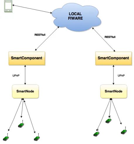
Firstly, for a better understanding of the work that has been developed and exposed on this thesis it is important to have an overview of the “principal/primary” architecture of a sensor cloud. Although this architecture differentiates in some ways from the one that has been implemented during the development of this thesis, it’s important to know all the stages of work that were needed to find the solution presented in this thesis, to show that the implementation proposed is indeed a better solution for this problem.
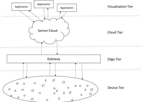
As we can see on figure 2.1 the architecture is divided in four important layers. The device tier defines the physical sensors that can work with different protocols and communication technologies making this environment heterogeneous. To homogenize we have the edge tier, which works as collector of data from the sensor and provides
Gateway Sensor Cloud
Application Application Application
Heterogeneous pool of physical Sensors
Device Tier Edge Tier Cloud Tier Visualization Tier
Figure 2.1: General Sensor-cloud architecture
this data to the upper layer in a way that can be understood and used. The Cloud tier represents the concept of sensor cloud, in which the main motivation is to allow users to remain unaware of actual physical location of sensor nodes through virtualization, decreasing complexity of management and making it available and usable through an application to all users in the visualization tier. One of the main objectives of sensor-could is to provide an “easy to use” environment to users who don’t have any technical expertises.
As said before, this architecture wasn’t the one used on the work developed on this thesis. The thesis was based on a previous work developed by Neto et al. (2014) [8]. The main concern of the present thesis is to integrate the work already developed on a different technology: FIWARE, with the intuit to replace the UPnP technology which doesn’t fulfill all the requirements and limitations imposed in the manufacturing industry.
The work developed fits under one European project SelSus and a brief expla-nation of the project will be given next.
2.2
European Industrial project
The work developed in the presented thesis can avail in the technological development of projects: SelSus [28], I-Ramp3 [17] and ReBorn [27].
2.2.1
SELSUS
European manufacturing competitiveness is based on technology innovation. Fierce competition from lower labor cost economies, particularly in the assemble sector, makes it extremely importance for European companies to improve the long term sustainability and competitiveness of higher technology production facilities.
Companies must be prepared to the continuous market fluctuations and changes in product part requirement that ultimately results in the rearrangement of the
pro-duction paradigm, aiming to achieve responsiveness. Therefore, the concept Self
Sustaining Manufacturing Systems was labored on this European project were the main concern is to prevent failures and extend lifetime of the machinery.
These concerns are extremely important, because if a machine fails completely, the production line in which that machine in integrated will stop. Consequently, causing not only waste of production time as may also damage raw materials, resulting in waste of money.
Selsus is a European project developed with the intent to create a new paradigm to the manufacturing industry, where a highly effective, self-healing production re-sources and system to maximize their performance over a longer lifetimes through highly target and timely repair, renovation and upgrading.
The development and integration of advanced sensor systems with embedded intelligence for data capture and integration within an assembly station. This system should exhibit interoperable, between multi-platform communication network, and delay tolerance capabilities. It will comprise sensors that may be embedded within equipment or external to the assembly station.The network will be capable of gener-ating large quantities of data relevant to the operational behaviour of the assembly station. This data has the potential to provide extremely useful information that may be used to predict system failure, effectively schedule maintenance, and optimize efficient energy use. This advanced sensor system is an essential cornerstone in the introduction of Sensor Clouds.
Within the sensor cloud the smart sensor nodes will have the ability to collabo-rate with other smart sensor nodes, to store data, analyse data, process and interpret events, communicate with different networks and be tolerant to communication of failures. This cooperation between nodes will allow individual nodes to share data processing, data storage, measurement capabilities and experience, creating the basis for sensor cloud.
2.2.2
I-RAMP3
I-RAMP3, Intelligent Reconfigurable Machines for Smart Plug&Produce Pro-duction, is an European project that aims to improve the manufacture industry by ap-pealing to innovative concepts towards of smart factory systems. In order to add intel-ligent to the shop-floor equipment, a new concept was developed NETDEV(NERwork-enabled DEVices). These component is implemented on all the manufacturing equipment both complex machines, as industrial PCs or PLC, and sensors & actuators -and has as main goal to accomplish a st-andardized communication, along with pro-viding intelligent function for negotiation between devices and Plug&Produce concept for easy device integration.
Since the use of sensors on a shop floor become fundamental to evaluate machine’s behavior while productive and surrounding environmental conditions, the lack of processing and memory capabilities associated to sensors are no longer an issue, because the NETDEV concept puts low capacity devices, such as sensors, at the same level of intelligence as complex machines and high capacity devices, such as Welding Machines and Metrology Systems or Robotic Arms.
Task collaboration between NETDEVs, e.g. when a complex machine requests a measurement task from a sensor, is possible due to a standardized proprietary language-DIL, used for NETDEV communication that eases the quick delivery and reception of device’s task execution capabilities and process information.
An I-RAMP3 version of the PlugThings Framework is being developed, which is used to integrate sensors of different manufactures on the system, with support for intelligent capabilities, such as self-diagnosis for sensor malfunctions and breakdown detection, self-organizing for reducing complexity on the communication and providing qualitative information, self-learning for sensor mote auto configuration according to device needs of task execution using OTAP technologies and automatic identification of sensor mote position [13].
Intelligent sensors will be applied on two specific demonstrators, in this case a Resistance Welding Station promoted by Technax and a Spot Welding Cell promoted by AWL, to solve real E-vehicles industry problems.
The Resistance Welding Cell uses a pneumatic resistance welding head to weld forks and wires, which will be components used on alternators and vehicles motors. To detect if a fork is present on the pallet for welding, a vision system - promoted by INOS, is used. Since luminosity conditions can negatively influence the vision system results, leading to false positives/negatives, Luminosity sensors are requested to evaluate the light conditions of the room, allowing an automatic calibration of the vision solution for a faster ramp up. On the other side, thermocouples are applied on the resistance welding head to evaluate the temperature variation of the electrodes during a welding cycle, allowing a predictive maintenance according to the electrodes wear. On the other side, the Spot Welding Cell is responsible to assembly a VW E-UP part, where Liquid Flow sensors are used during the welding job to monitor the state of a cooling system of the welding cell.
2.2.3
Reborn
The vision of ReBorn is to demonstrate strategies and technologies that support a new paradigm for the re-use of production equipment in factories.
The decision on the re-use of production equipment requires knowledge about the actual status of the machine and its components after the past use and the adjustment and/or prediction of the operating, service and maintenance characteristics, which have changed due to wear, exchange, update and other influences during the past
operations. In addition, the information acquired might be useful for predicting
possible changes of these characteristics during a foreseen operating period. The
creation of this information requires an assessment of the operation so far (with the initial conditions as a base line), which is characterized by the executed processes, the deployment conditions, the supply data, sensor data, quality data and logs about failures, faults and service, maintenance and calibration measures.
The main purpose of ReBorn is to assess various potential change, upgrade, reuse, dismantle and disposal possibilities and the corresponding reconfiguration effect on the overall system and on the overall system cost, performance and status throughout the life-cycle assessment recurring to key performance indicators.
This is done by running what-if simulation scenarios on the virtual agents’ representation of the equipment in the virtual design environment in order to estimate the likely impact on the physical system before making a change recommendation to said equipment.
Such new strategies will contribute to sustainable, resource-friendly and green manufacturing and, at the same time, deliver economic and competitive advantages
for the manufacturing sector. Furthermore, ReBorn aims at delivering industrial
environment proven prototypes. A special feature is the versatility of these prototypes which can be integrated either modularly or within inclusive factory layouts. Finally, in the light of ever increasing importance of knowledge based economy, the re-use and refurbishment approach will give rise to new business model opportunities in particular related to providing services as an added value.
2.3
Technology
In this section the UPnP standard will be explained together with its advantages and disadvantages, since it was the main reason for the development of this work.
It will be also presented cloud providers an their types of cloud, IaaS/PaaS/SaaS, and a comparison between them to find which is the best fit to our problem.
2.3.1
UPnP
UPnP is an open standard supported by leading software and hardware manu-facturers such as Intel, cisco, Samsung, LG Electronics, and implemented by hundreds of companies.
The UPnP Device Architecture Version 1.1 and an additional twenty-one (21) UPnP Device Control Protocols specifications were adopted and published by the International Standards Organization (ISO) and International Electrotechnical Com-mission (IEC) as International Standards in the fall of 2011. Eight specifications were also published as updates to previously published ISO/IEC International Standards (ISO/IEC 29341-x).
Universal Plug and Play (UPnP) is a peer-to-peer light-weight standard with APIs for most programming languages and running on most operating systems. The
framework is based on IP and is offering addressing, discovery, description, control and event notification or alternatively presentation services. UPnP mainly addresses the integration of devices such as PC, printers, NAS, cameras in a local network [1].
The UPnP standard presents many advantages that must be highlighted, it allows true plug and play compatibility with all UPnP-enabled devices, achieved with a transparent communication, being important for the concept of smart factory. This standard is also very easy to install and to use during development, and is supported in several programing languages.
Although UPnP also has disadvantages. It can cause heavy network traffic, and in the worst case scenario is when the booting occurs, where each device has to communicate with every other device on the network, so the number of messages being transmitted could became very high. This could temporarily slow the network down if only limited bandwidth is available.
Another issue that this standard carry is related with security. Shared files or folders could become available to external sources via the network, so third party security software may be required to block this [35].
2.3.2
FI-PPP
The vision of the Future Internet Public-Private Partnership [10], short FI-PPP, programme is to contribute for the sustainability of the European Economy. It aims to achieve this vision by developing an innovative future Internet technology for smart infrastructures, which will be the basis for sustained competitiveness and growth of Europe.
The FI-PPP programme is part of the EU’s Seventh Framework Programme and receives founding from the EC.
This programme is divided in three phases 2.2 from 2011 to 2016. Phase 1 focus on the development of architecture and generic and specific enablers. Phase 2 has as main goal the development of a core platform and use case of specific functionalities. Phase 3 aims to provide a stable infrastructure for large-scale trials and prove the viability of the concept.
Figure 2.2: FI-PPP Programme Architecture [10]
2.3.2.1 FIWARE
The purpose of FI-PPP is to accelerate the development and adoption of Future Internet technologies in Europe. As explained before, FI-PPP is divided in three main phases, being FIWARE one of the main projects and its development extends through the three phases.
The FIWARE platform was born on an European project in 2011 in which the main goal was to build the Core Platform of the Future Internet creation and delivery of versatile digital services while providing high QoS and security guarantees with the intent of increasing the competitiveness of the European ICT economy, by developing an innovative infrastructure. To fulfill all the objectives, FIWARE was designed to meet the necessities of a major part of the different sectors and provide a powerful service to stimulate and cultivate a sustainable ecosystem for both service providers and end user.
FIWARE is an open-source technology, based on elements called Generic En-ablers(GEs) providing reusable and common functions applied in a multiplicity of Usage Areas. It must be highlighted that not all the services can be applied to mul-tiple areas across various sectors. A Domain-specific Common Enablers(Specific Enabler) was design as a enabler that have a concrete area of focus, meaning that all the enablers create upon this criteria are made to solve a particular Area [5].
The Core Platform of FIWARE is divided in disciplines, where Generic Enablers were developed to be linked with which of the following FIWARE Technical Section:
• Cloud Hosting
As already mention the FIWARE aims to help in the development of the Euro-pean economy, and for this purpose was considered crucial offer a service that benefits small medium enterprises and start-ups. Thus, cloud hosting service is offered to anyone, to use and pay according to their needs and possibilities. Therefore, when the business starts growing they can easily increase their re-sources on the cloud by asking for more. The preference for this type of service lies with the initial investment that is greatly reduced.
This way generic enablers that are based on designing an innovative cloud infrastructure were developed under the scope of this FIWARRE chapter. “Building upon existing virtualization technologies, FI-WARE will deliver a next generation Cloud Stack that will be open, scalable, resilient, standardised, and secure, and will enable Future Internet applications by providing service-driven IaaS and PaaS functionalities and extending the reach of the cloud infrastructure to the edge of the networks, much closer to end users.” [36]
• Data/Context Management
The purpose of this FIWARE section is to enable a smarter and context-aware applications and services, achieved by a collection of generic enabler able to data collect and effective accessing, processing, and analyzing massive volume of data. Nowadays, the term “big data” is getting more attention being related with the analysis of massive data and trying to give meaning to it by apply data analysis algorithms. Thus, this FIWARE section aims to provide a outperforming GE that will ease development and the provisioning of innovative application for the exploitation of massive data.
A cornerstone concept within this section is the structural definition of data elements thus, the NGSI protocol was defined. This protocol will be further explored in a following chapter of this thesis.
• Applications/Services Ecosystem and Delivery Framework
Applications/Services and Data Delivery section aims for the creation of an ecosystem of applications, services and data that is sustainable and promotes innovation.
• Internet of Things (IoT) Services Enablement
In this section, the FIWARE purpose is to build relevant Generic Enablers for Internet of Things. This aims to make the knowledge collected from the
real world available, searchable, accessible and usable from the Internet. Thus, services are made to obtain value from the data collected.
• Interface to Networks and Devices (I2ND)
This FIWARE technical section aims to provide an open and standardized network infrastructure by the development of generic enablers for this end. This network infrastructure must be able to deal with the more sophisticated terminals and proxies, on one side, and with the network operator infrastructure on the other side.
• Security
“Internet of Service” - service-oriented architecture where collaboration be-tween service and service producer occur- is the most expect function when talking about future Internet.
In order for a IoS system to be successful requirements must be achieved, espe-cially the necessity of individualization. This is the most challenge requirement, once that the information provided from the users must be kept secure.
Therefore, Future Internet services are constantly exposed to threats that can compromise the data or even misuse and damage the system.
Given this challenge and concerns of Internet of Service, the concept “secure by design” came on FIWARE. This aims to address the secure properties of both the platform and applications. As much, a security architecture will focus on security function such as identity management, in order to create a Generic security Enablers.
• Advanced Middleware and Web UI Architecture
In order to become widely visible and adapted by end users, the FIWARE platform offer server functionality but also offer a improved user experience. Thus, two different areas are offer by FIWARE through Generic Enablers Ad-vanced Middleware, this means a traditional web service(REST), adAd-vanced web-based user interface, that aims to improve the user experience.
Each and every one of the disciplines presented above has already Generic Enablers to fulfill their objectives. For a better organization and availability a FI-WARE Catalogue was created, it contains a public royalty-free and open source library of components (Generic Enablers) with reference implementations that allow
developers to test and experience the functionalities already developed and making the programming much easier and efficient.
2.3.2.2 FIWARE-LAB
As a branch of FIWARE that was launched on 6 September of 2013, FIWARE-lab is a non-commercial environment that offers and shares resources of both hardware (cloud) and data to all the users (both individuals and entrepreneurs).
The FIWARE-lab and all its features are available through a web-page with the two main environments: the cloud, where the collection, storage and processing of data is done, and the environment applications and services, with the highest focus in data visualization. This is the conventional way to use these two “environments”, but of course they can be used in various ways.
The platform provides a great medium for development, testing and use of numerous services, apart from providing a stable and free environment to all users. In addition to being used for development, users can also take advantage of all that has been developed so far since the generic enablers FIWARE developed within the project are freely released on the FIWARE-lab, providing a first contact with the more peaceful cloud environment. It is also noteworthy that a large number of applications developed by users are available in FIWARE-lab for free or with an associated cost
The FIWARE-lab is deployed over a geographically distributed network of federal nodes all over Europe. It should be highlighted that several cities are already connected or are currently working on setting up a connection to the FIWARE-Lab in order to export their open data in this environment.
2.3.2.3 FITMAN
The FITMAN [11] belongs to the phase II of FI-PPP and is focused on solving problems associated with manufacturing. As FIWARE, the FITMAN main purpose is help European economy to grow sustainable.
In order for the FITMAN fulfill its goals of helping the manufacture industry, FITMAN teamed up with 10 industry-led as case of study, belonging to different branches of industry. The FITMAN found in the FIWARE technology the flexibility to reach success.
Given the wide range of industrial fields the project was forced to split their forces in three paradigms:
• Smart Factory Platform
This platform was built to deal with the optimization of the production process (production cost, energy efficiency, production reliability, production machine usage). This is accomplished by monitoring and management of the production lines and the machinery. The main goal is to collect information from the shop-floor to support decision making.
• Digital Factory Platform
This platform is intended to facilitate quick and cost effective development of innovative services, it is also oriented to help workers performing their tasks. The platform is specifically intended to provide support in the development of advanced and 3D visualization services and applications.
• Virtual Factory Platform
This platform can be seen as a business collaboration platform, where actors of the virtual enterprise can collaborate among themselves in order to achieve business goals. The key functionality provided by this platform includes tangible and intangible asset management and collaborative business process execution.
So far 15 Specific Enablers have been developed and divided into this three solutions. It should be noted that some of the developed Specific enablers can be integrated in solutions of problems not related to manufacturing, especially the Specific enablers developed within Virtual Factory.
The problem study with the presented thesis, is a clear analogy with the smart-factory paradigm presented in the FITMAN project. For this reason it was important to study their solutions to find the best approach for our goal.
2.3.3
Other Cloud provider approaches
There are enormous cloud providers like, amazon cloud drive [22] or rackspace [26]. This companies provide cloud solutions using the conceptual business model, where every resource usage and rental has a price based on the usage time and amount. These solution are not appropriate for the problem of the industry, that aims to
achieve a more flexible way to treat and analyse all the data collected by the sensors, by the fact they only act as Infrastructure as a Service, meaning they only provide the “hardware”, management and other basic services.
Another setback of this approaches is the service model they provide. These companies provide an Infrastructure as a Service, and the most convenient model would be SaaS. This meaning they only provide the “hardware”, management and other basic services
For this thesis we are looking for a Software as a Service approach, like the FIWARE platform, and for this reason this type of cloud providers do fulfil our goals and requirements
2.3.3.1 Virtual Fort Knox
During the study to find out what the best approach to our problem, we came across Virtual Fort Knox (VFK), cloud-based Platform for distributed service-oriented application [16] .
The Virtual Fort Knox cloud platform was launched into the market in October first 2013 with the intuit of offering a new solution for the manufacturing industry. With this new solution, the company behind VFK wanted to create a solution capable of combine different approaches already used in the manufacturing in a community cloud platform.
Although the similarities of this platform and the FIWARE platform, ie create an enablers structure in order to modify and interact with the problem, we found key issues in the VFK platform such as: is paid, is closed source.
The fact that the Platform is closed source, might restrict approaches that are required by the environment on the shop floor. Therefore FIWARE can be much more flexible, making more easy to find and work a solution for the industrial manufacturing problems.
One of the biggest concerns of this platform fells with the lack of security, despite using the same principle of FIWARE, “security by design”, does not allow the development of any security software by cloud users or third party entities [2].
For all of this concerns and the fact that FIWARE is an European project, just like the one this thesis is integrated, this platform does not accomplish all of our
requirements.
2.3.4
Challenges of industrial WSN
Nowadays with the increasing age of many industrial systems and the dynamic industrial manufacturing market, intelligent and low-cost industrial systems are
re-quired to improve the productivity and efficiency. With this necessity, Industrial
WSNs became more and more desirable mostly because of several advantages includ-ing self-organization, rapid deployment, flexibility and inherent intelligent-processinclud-ing capability. But, every-time new technologies are developed, new challenges appear.
A IWSN is composed by many sensor nodes which are a challenge per se, due to their limited resources of energy, memory and processing power. With this physical limitations it is hard to accomplish a few of the requirements imposed by the network in order to work properly.
Connectivity is a huge problem due to industrial environment: high humidity levels, vibrations, dirt and dust, and other conditions cause interferences on the signal producing packet errors and affecting the wireless links characteristic varying over time and space. Thus, capacity and delay of each link is location-dependent and is continuously varying, making QoS extremely difficult to achieve.
Quality of Service(QoS), measures the confidence that IWSN users have on the values obtained, they must reflect what is actually occurring on the industrial environment. Any difference of state can lead to a wrong decisions on the monitoring system.
Security should be an extremely important feature in the design of IWSN to maintain the communication safe from external attacks and intrusion. Active At-tacks consist of modification, fabrication and interruption of communication or even
of nodes, being extremely dangerous because it could mislead the users. Denial
of Service(DoS) attacks require some attention since the network becomes totally unavailable to its intended users.
To deal with technical challenges and still meet the diverse IWSN application requirements it is important to adapt the design of the network in such a way it fits the problem but it is still reliable [15].
2.3.5
Challenges of Sensor-Cloud
Like the wireless sensor networks, sensor-clouds introduced important challenges that must be overcome. Requirements like fault-tolerance and reliable continuous transfer of data from sensor devices to the server are important issues when designing the sensor-cloud.
The more complex the sensor network gets, the more sensing capabilities it has. In the order hand it gets more exposed to breakdowns, and therefore the potential for a sensor error will be increased, diminishing the credibility of the information shown on the sensor cloud.
In large networks like IWSN it may be possible to generate extremely large data streams that might not be efficiently processed. As a consequence of this inefficiency, the large quantities of data that will be generated must be analysed in order to be usable.
Alongside the previous problem a new one was exposed: bandwidth limitation. This problem has to be handled in sensor-cloud systems when the number of sensor
devices and their cloud users increases dramatically. However, there are several
bandwidth allocation methods to resolve these issues but are beyond the scope of this thesis.
A careful network topology must be thought not only to optimize bandwidth, but also deal in an efficient way with the large amount of networks needed in a sensor-cloud architecture.
Sensor-clouds works upon event processing. The management and use of this characteristic raise a few key questions concerning: event synchronization when delays occur on the network; support of different events and messages; the optimal way to deal with enormous amount of events [4].
Chapter 3
Background & methodology
Considering the premises that constitute the work objective we will first explain what are the principal properties of the SmartComponent and what are the limitation that we must attack.
Then the methodology design to mitigate the limitation and restriction imposed in the mentioned component will be explained.
3.1
Existing SmartComponent implementation
Figure 3.1: Physical Architecture Monitoring Production Line [8]
layer of the architecture. These devices communicate between them and with the SmartNode using different protocols, consequently creating a heterogeneous network. Therefore the SmartNode, which the main function is to serve as a gateway, must be prepared to deal with all protocols and be able to send the information gathered to the SmartComponent, this communication is done using the UPnP protocol.
The SmartComponent is the component of WSN that brings together instant data collected directly from sensors or indirectly, by gateways. This component creates a virtual abstraction of devices, in other words encapsulates the device heterogeneity in a way it makes them homogeneous and is where data is subject to the first analysis, reducing the amount of information sent to the upper layers. To achieve this analysis very simple algorithms are used. This study of the data can be used as a trigger to warn any unexpected changes allowing the users to take precautions.
To perform the analysis of the data is necessary to establish a relationship with the devices on the network. To accomplish this a Registry Service was created to discover, register and maintain all the detectable devices on the network.
The SmartComponent also provides a distinguishing feature, the capability to wire new services (software components), built on demand, and new data analysis modules for later individual control of working cells at the Shop-floor. It is mandatory that the device or devices, that receive the new instructions, allow dynamic integration of the software components [20].
The concerning point of this component and architecture is the protocol used to accomplish the communication, in this case UPnP, that is used for both upper and lower layers communication. This protocol fits some requirements of the architecture presented, the transparency in the communication between heterogeneous systems is perhaps the most important one.
3.1.1
Technology Limitations
Considering that the presented work aims to improve an already developed Wireless Sensor Network component, the SmartComponent. the reasons for this alteration must be explained, exploring the limitations and drawback of the first approach.
The reason behind this modification falls on the fact that UPnP isn’t the most 34
suitable protocol for the environment of a shop-floor. This protocol has as its biggest problem the amount of message it uses to maintain the state of all the network participants. In addition to this problem, the UPnP was designed mostly for home use, this means that it is not prepared for the huge amount of devices that a WSN has. Therefore it became extremely necessary to find a way to minimize the UPnP use in this type of networks.
Besides this problem, the lack of security the UPnP standard presents is con-cerning for the manufacturing industry. Once any device, even malicious ones, can enter the UPnP network and behave as UPnP device, send messages, subscribe to services and receive data, this behavior is worrisome.
Moreover, when creating a complex service the SmartComponent also launches UPnP instances, increasing the amount of memory needed to maintain the system working with all its capabilities. This means that this network component will face some scalability problems affecting the whole shop-floor network design.
3.2
Development Methodology
In order to solve the existing SmartComponent efficiency problems, some studies on current cutting-edge technologies were made to find the best solution to improve this system without compromising the work already developed. The most promising technology found to achieve our goal was the FIWARE platform.
To get the most out of this recent technology, its features and capabilities were studied and several approaches were tested. From this work, we came to understand that the FIWARE is very context-oriented, which means all data sent to this technol-ogy has to have a well defined context.
To deal with context-based architecture and to ensure compatibility between all the generic enablers a protocol was defined by the FIWARE community. This protocol, known as FIWARE NGSI Context Management, proved to be one of the most important parts on the development of the present work.
FIWARE NGSI Context Management specifications are based in the NGSI Con-text Management specifications defined by OMA (Open Mobile Alliance). NGSI is a XML/JSON definition protocol, that ensures interoperability with the numerous FIWARE Generic Enablers and it is composed by two different interfaces built in a
RESTfull form: NGSI-9 and NGSI-10.
NGSI-9 is a context entity discover interface and its main purpose is to register and update the context entities, their attributes and availability. Meanwhile NGSI-10 is a context information interface that deals with everything associated with the context information of the context entities.
While being different protocols designed with different purposes, the main com-ponents of both are described in the following list:
• Entities: Virtual representation of physical objects; • Attributes: Information associated with Entities; • Attribute: domain logical group of attributes;
• Context Elements: the container used for exchanging information about en-tities.
Figure 3.2: Physical Architecture 36
In the first approach of this component the UPnP technology was used in all communications, both the upper and lower layers. To make this component compliant with FIWARE a new interface to communicate with the upper layer, in this case the cloud was developed.
Given the fact that the FIWARE is context-based, to have a compliant technol-ogy we had to accommodate NGSI in our component. To do this we implemented a REST interface in the SmartComponent to communicate with a context broken in the cloud, as demonstrated in the figure 3.2.
3.2.1
A REST-based Approach
Representational State Transfer(REST) is a client-server architectural style that induces desirable scalability, usability, accessibility, and decentralized growth as well as allowing for greater design flexibility. This architectural style also specifies some constraints to improve the user experience and still maintaining the management of the server effortless.
The communication with FIWARE cloud is based on a RESTfull design for two main reasons: first, REST allows for easy adaptation to the number of users, during the periods of high usage the number of servers increases from one instance to hundred in a extremely rapid and effective way. The fundamental principal of REST style requires that client interacts with the server in a standardized interface allowing to have a stateless service, where each transition is independent, removing
the need of a maintenance state by the server (there is none). Thus, any server
instance can respond to any incoming request from clients. Scalability is a really important fact for a WSN due to the large amounts of data that can be generated in certain occasions. Second, the REST approach simplifies the development of client application and doesn’t require any special components. RESTfull client requires very little overhead, which is really advantageous when operating with WSN. In addition to ease the development of applications on FIWARE, the RESTfull approach offers a design that also makes it easy to incorporate some of the underlying data, metrics and other items for users without the technical expertise, this was an important aspect while designing FIWARE [3].
For the purpose of this thesis RESTfull approach is also superior to the one used before, UPnP. The most distinctive fact, and obviously more advantageous is the in-existence of requisites on the network, there is no requirement for the devices to use the same local network, like in the UPnP technology.
3.2.2
Context Broker
Brokers, or publish/subscriber systems, are becoming more and more popular when it comes to build a distributed information system. Subscribers demonstrate to the system the interest on certain set of subscriptions, while publishers submit new information to the system. When the system receives this new information matches it with a subscription and notifies the interested subscribers [7].
To better understand the concept of context broker, first, we need to establish a definition for context.
All the data existent in the world exist in a context. In other words, data only has meaning when is related to something or has a relation with other piece of data. The isolated data loses its big potential, but in the right context that simple data becomes extremely relevant and offers, the people working around the collected data, important knowledge.
The context broker helps to form a context. It does this, by taking isolated data and putting them in a relevant context (irrelevant context is as worthless as no context at all), then seeks to trigger some “context event” generating in this stage data with some relevant meaning and opens the possibility to make decisions that can only be made with information with meaning.
When developing a Data/Context scenario, a context broker is a must have component, because it is crucial in this kind of architecture to have a component to mediate between consumer producers, in this case the sensor devices, and the context applications that can be some data processing algorithms or some kind of data visualization.
The FIWARE catalog of generic enablers provide us with a broker with this definition, Orion Context Broker [6], this will be used to achieve our goals in the communication (using REST interfaces implemented on both sides)with the FIWARE cloud.
Chapter 4
Implementation
The motivation behind the European Industry efforts to give a step forward in the smart factories approach, is to achieve a stable and secure monitoring of it’s equipment and production line.
This chapter’s purpose is to provide a notion about the relation between present European industrial needs and the work concerning points. By the end of this chapter, we expect to depict a more profound vision over every requirement and solution coupling.
In order to better explain the work developed, two major sections were written. The first aims to study the FIWARE technology with the objective of adapting SmartComponent to it, extracting the best out of both technologies.
The second section is based on the requisite confidentiality required by the industry. To archive this objective a private implementation of FIWARE was deployed, and used as a test bed.
4.1
Porting the SmartComponent to the FIWARE
SmartComponent as it has already been explained before is the component where information converges to be processed. It is in this component that the collected data is pre-processed in order to be sent to the cloud, where a more complex analysis can be done and the results stored.
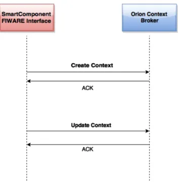
Smart-Component and the context Broker on the cloud. To port the SmartSmart-Component to be able to use this kind of communication changes were need to be done on the SmartComponet.
Figure 4.1: Communication General States
The CreateUpdate shown in the image 4.1 is the NGSI specification. In order to join all the information of a component we have to create it first. This is done
using the XML shown in the listing 4.1. This is a CreateContext XML because
on the “updateAction” attribute it has the “APPEND” value. The Update context communication uses a similar file but instead of “APPEND” it has “UPDATE”.
This new XML is more detail given the need to create a context to work the information when it reaches the cloud. This context was not necessary in the previous version, because in order to receive data, it was required to subscribe to the UPnP complex service, thus this context was inherent, since the server used subscription ID to identify the data.
<?xml version="1.0" encoding="UTF-8"?>
<updateContextRequest> <contextElementList>
<contextElement>
<entityId type=”shop−floor” isPattern=”false”> <id>Room1</id>
</entityId>
<contextAttributeList> <contextAttribute>
<name>temperature</name> <type>float</type>
<contextValue>23</contextValue> </contextAttribute>
</contextAttributeList> </contextElement>
</contextElementList>
<updateAction>APPEND</updateAction> </updateContextRequest>
Listing 4.1: Sample Context XML with APPEND updateAction
In order to achieve communication with the cloud and send data to it, the SmartComponent must interact with the server using a global identifier(HTTP URI’s), like the one we used to communicate with FIWARE-lab, and can be locally accessed by the following url:
http://130.206.119.223:1026/ngsi/updateContext
For this a web-service was developed to perform HTTP POST to send the data generated to the cloud.
4.1.1
Instance on the FIWARE-lab
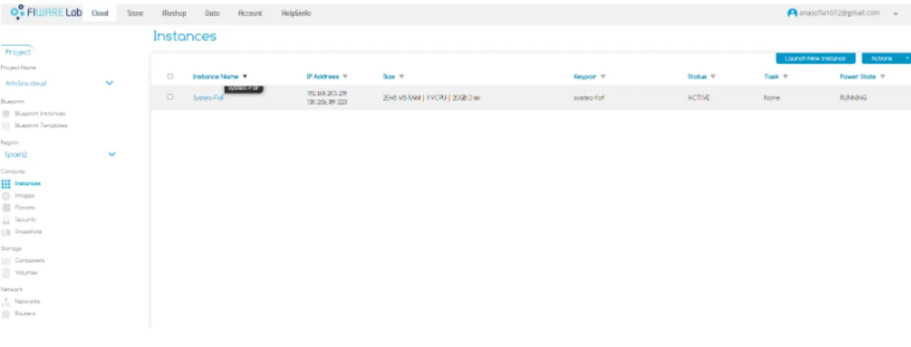
On the side of FIWARE-lab it was necessary to install an instance of Orion context Broker, which is available in its FIWARE catalogue as generic enabler on Data/Context Management. The description of the installed instance can be seen in the following image 4.2 .
After the installation was finished it was necessary to remotely access the ma-chine to start the context broker process simply using the command “contextBroker -port 1026”.
This required making changes to the network rules assigned to our public IP. For this we only need to access the FIWARE-lab interface, as shown in image 4.3, and
Figure 4.2: Instance Settings
create the rules we found necessary to the work we needed to develop. For this work two rules were created one to allow the communication with the broker on port 1026, and another rule to allow remote access to the instance using ssh [29].
Figure 4.3: Network Rules
After executing all of these steps, we had a Generic Enabler working perfectly on FIWARE-lab. Meaning we finally could start communicating with the cloud.
4.2
Local Implementation of FIWARE
infrastruc-ture
One of the great challenges that the IoT brings is confidentiality. This is without a doubt one of the most important factors for the industry, since in order to be competitive and keep creating innovative products, secrecy is a fundamental factor or else others my gain unwanted advantages on the ever more competitive market.
FIWARE alone does not provide a solution to this problem because of its public
nature. In order to find a work around, a solution was designed to address this
deficiency.
The solution designed to solve this problem was to bring the FIWARE technol-ogy, in this case the cloud, from the public deployment method to a private domain, thus restricting the data access to a controlled group in which they could trust. Using this local approach, it is possible to keep all the sensitive data in the restricted access cloud and still do processing on the public domain, thus obtaining a hybrid model.
4.2.1
FIWARE Installation ToolBox
Cloud infrastructures are very complex pieces of software that have to be installed (deployed) on multiple machines (virtual or bare metal) and they have to be perfectly synchronized and configured in order to reduce problems. Because of this reasons it felt important to the FIWARE project to create a way to facilitate installation of the nodes, instances of cloud, as it becomes necessary to grow their infrastructure without having to spend more resources. Now the project counts with approximately 14 nodes across Europe. In order to achieve this goal, a project named FUEL [12] was used and modified to the intents of FIWARE.
FUEL attempts to automate the installation and maintenance of OpenStack [REF TO SITE], because a full manual deployment would be very complex, time-consuming, prone to mistakes on the deployment process, testing and maintenance. Therefore, FUEL developed a simplified and flexible way to accelerate this task, using a complex ISO package with scripts of installation and providing all the software necessary for a stable and functional OpenStack environment.
In the following image 4.4 we can see the main components of the package needed for installation of FUEL. In order to have to have a complete package you must provide
all the operating systems, being the most commonly use in this package SUSE [33] or Ubuntu [34]. For setup and installation the puppet software is used. This software is an open source configuration and management utility, and should be noted that puppet scripts are used to make this installation and configuration of the components in the FUEL network as also on the OpenStack configuration and deployment, becoming one of the most important components of the FUEL package. It is also necessary to include in the package all the components of OpenStack.
Figure 4.4: Fuel Package
The FIWARE project team had to modify the original FUEL package to one that fulfil the requirements, this was achieved by adding more puppet scripts.
One of the scripts that must be highlighted is the FIWARE-Lab which was created to connect the new node to FIWARE structure, this means that any cloud created with this settings is automatically connected to the structure of FIWARE-Lab. As a consequence, to get a local implementation, it was necessary to remove the FIWARE-lab script.
The disconnection from the FIWARE structure brings disadvantages. The most relevant is losing the maintenance provided by FIWARE project, which includes the provision and the automatic update of Generic Enablers that otherwise are done by the local administrator, thus occupying time.
Seeing that the deployed cloud in this work wont have the official support from the FIWARE project, only the use of their innovations will be made.
4.2.2
FUEL and OpenStack
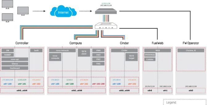
The following image 5.1 shows the network topology for a bare-metal installation. This kind of installation was not possible because of the large equipment requirements. Therefore, a virtual installation was done instead, the behaviour and components are exactly the same, thus, the same network topology was used.
Figure 4.5: Network Topology for Fuel and OpenStack projects
As we can see in the network topology, the FUEL operates in the native vlan, which is to say that their packages have no tag referring to vlan, which can be seen as a weak point, since this may raise security issues . Although the existence of this possible security issues, all installation configurations and the software itself are transmitted by native vlan. Internally the OpenStack communications are made using vlan 100, or management vlan as described in the image.
OpenStack [23] brings together a collection of software tools with the purpose of building and managing cloud computing platforms.
OpenStack allows users to deploy to virtual machines and other type of instances used on OpenStack, which handle different tasks for managing a cloud environment
on the fly. It makes horizontal scaling easy, which means that tasks which benefit from concurrency can easily serve more or less users on the fly by just spinning up more instances. For example, a mobile application which needs to communicate with a remote server might be able to divide the work of communicating with each user across many different instances, all communicating with one another but scaling quickly and easily as the application gains more users.
The three OpenStack components represented on the figure 5.1 (Cinder, Con-troller and Compute) work together on maintaining an operational cloud. The main function of the Compute node is to manage the “virtual machines” installation and positioning with the objective of maximizing the use of the available resources.
Controller node focus on managing and configuration the OpenStack environ-ment and is the most important component of the OpenStack architecture.
Cinder which is more analogous to the traditional notion of a computer being able to access specific locations on a disk drive. This traditional way of accessing files may be important in scenarios in which data access speed is the most important consideration.
4.2.3
Installation process
Virtual installation requirements: • Quad-core CPU
• 8+ GB RAM • 128GB disk
• Enable virtualization
In order to proceed with the installation (it must be kept in mind that a virtual installation was done) it was necessary to create a similar network as the already
displayed in a virtual scenario. Four virtual machines were created within that
network, one of the machines was used to install the FUEL and the remaining were used for the OpenStack components.
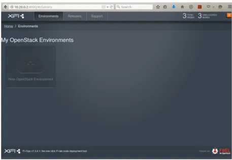
Once the FIWARE created FUEL package finished its installation, a web inter-face similar to the one displayed on figure 4.6 is provided to the system administrator, allowing to continue the installation using a graphical interface.
It is very interesting and important to notice that although no OpenStack or FUEL software was installed at this moment on any of the other virtual machines,
they were automatically detected by it, as Unallocated Nodes. This detection is
important because it is through this feature that the installation is allowed, and if the virtual machines weren’t detected, that would mean the network configuration was not working properly.
Figure 4.6: Web-interface of the FUEL server
To proceed with the installation an OpenStack environment must be created and all environment settings must be chosen. This configurations, shown in figure 4.7, defines how the OpenStack will works and if it has any additional service of control or management, like nagios[21].
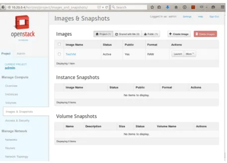
Then by attributing the machines not allocated to an OpenStack components, the FUEL starts the deployment and sets the configurations in each, and we finally achieve a functional OpenStack cloud 4.8, similar to the FIWARE. As the FIWARE-lab script was removed, the original web-interface is used to operate with the cloud. It must be noted that within this structure several OpenStack environments can be deployed and used to different ends.
Figure 4.7: Settings of OpenStack Environment
Figure 4.8: OpenStack environment interface
![Figure 2.2: FI-PPP Programme Architecture [10]](https://thumb-eu.123doks.com/thumbv2/123dok_br/18809569.926516/32.892.279.645.157.413/figure-fi-ppp-programme-architecture.webp)
![Figure 3.1: Physical Architecture Monitoring Production Line [8]](https://thumb-eu.123doks.com/thumbv2/123dok_br/18809569.926516/41.892.268.664.739.1015/figure-physical-architecture-monitoring-production-line.webp)