João Francisco Favinha Ameixa
Licenciado em Ciências da Engenharia BiomédicaElectronic States Characterization Of the
Anesthetic Halothane by High Resolution
Electron Energy Loss Spectroscopy
Dissertação para obtenção do Grau de Mestre em Engenharia Biomédica
Orientador:
Filipe Ferreira da Silva,
Investigador Auxiliar FCT-UNL,
Universidade Nova de Lisboa
Co-orientador:
Paulo Manuel Assis Loureiro Limão Vieira,
Professor Associado com Agregação,
Universidade Nova de Lisboa
Júri:
Presidente: Prof. Doutor José Paulo Santos
Arguente: Prof.aDoutora Ana Maria Botelho do Rego Vogal: Doutor Filipe Ferreira da Silva
Electronic States Characterization Of the Anesthetic Halothane by High Reso-lution Electron Energy Loss Spectroscopy
Copyright cJoão Francisco Favinha Ameixa, Faculdade de Ciências e Tecnologia, Uni-versidade Nova de Lisboa
A
CKNOWLEDGEMENTS
Dr. Filipe Ferreira da Silva and Prof. Dr. Paulo Limão-Vieira for their constant supervision, encouragement and availability throughout the course of this work, and for the laughs and all the patient to answer my countless questions.
Prof. Masamitsu Hoshino, Prof. Hiroshi Tanaka and Prof. Gustavo García for visiting our Lab, expertise and the opportunity to discuss our results.
My fellow colleague MSc. Guilherme Meneses for all the expertise, availability, of course, all the good times and laughs at Lab. I have to acknowledge you for making my path easier and enjoyable.
CEFITEC, the Atomic and Molecular Collisions Laboratory and the The Department of Physics, Universidade Nova de Lisboa for the provided working conditions.
All the remaing members of the Atomic and Molecular Collisions Laboratory, espe-cially to all the colleagues of the RABBIT PhD Programme, namely Mónica Mendes and Telma Marques, and, of course, my Brazilian colleagues Emanuele Lange, Alessandra Barbosa and Diego Pastega for all the delightful moments at the Lab and for the insightful discussions. My colleagues PhD student Tiago Cunha and Mr. André Rebelo for the all delightful moments, knowledge and for the moments past together.
My dear Aunt Adelina and my cousin Hugo for hosting me in the past five years and for all the unconditional support and dedication. My acknowledgement to my aunt is only a poor way to express my indebtedness to you.
My family, especially my grandparents for the love and support.
My for life friends who made my work easier. I acknowledge each one of you for all the good moments we have been through together. There are no words to express a life time friendship.
All my friends whose names were not mentioned. If you are one of them and you are reading this, thank you for all the moments and (crazy) episodes.
"What we observe is not nature itself, but nature exposed to our method of questioning." Werner Heisenberg
A
BSTRACT
The interaction of ionising radiation with the biological environment, produces a set of secondary species along its track with particular relevance to low-energy electrons (LEE) (<20 eV) at a rate of∼104/MeVof incident radiation. We note that these LEEs are the main agent causing direct damage to DNA/RNA strands and play a key role in the presence of radiosensitizers which have been extensively used in radiotherapeutic procedures in cancer treatment. In order to comprehensively describe the underlying molecular mechanisms of such electron interactions with radiosensitizers, since a recent literature survey has indicated scarce or event absent studies on those molecular targets, in this thesis we present a set of novel experimental investigations on a prototype radiossensitized biological tissue equivalent molecule (TEM), halothane,CF3CHBrCl, as well as used as anaesthetic compound. We report a set of electron energy loss distribution functions under dipolar and non-dipolar conditions, with the particular relevance to the low-lying triplets states of halothane. Such studies have been performed in a crossed electron-molecular beam experiment where high-resolution electron energy loss spectroscopy (HREELS) data has been obtained. This will then serve as one of the input parameters in modelling the nanoscopic effects of radiation damage to TEM in Low Energy Particle Track Simulations within the clinical environment.
Keywords: halothane, radiosensitizer, electron scattering, dipole allowed transitions, singlet-triplet excitation
R
ESUMO
A interação de radiação com meio biológico produz várias espécies secundárias, nome-adamente eletrões secundários de baixa energia (LEE) (< 20eV) a uma taxa de∼104/MeV
de radiação incidente. Verifica-se que os LEEs são os principais agentes de dano nas cadeias de DNA/RNA e têm um papel decisivo na presença de radiosensibilizadores que têm sido vastamente utilizados em procedimentos radioterapêuticos no tratamento de cancro. De forma a descrever claramente os mecanismos moleculares subjacentes à interação de LEEs com radiosensibilizadores, uma vez que na literatura estudos sobre inte-ração da radiação com estes alvos moleculares são escassos ou até inexistentes, no âmbito destas tese foram efectuados estudos de interacção de LEEs com halotano,CF3CHBrCl. Halotano,CF3CHBrCl, é usado comumente como anestésico e é considerado como pro-tótipo molecular equivalente de material biológico (TEM). Neste estudo obteve-se o primeiro conjunto de funções de perda de energia de eletrões em condições dipolares e não-dipolares, com especial relevância para os estados tripletos de baixa energia. Estes estudos foram efetuados num aparelho de feixes cruzados onde foram obtidos resultados de perda de energia de eletrões de alta resolução (HREELS). Estes dados serão utilizados como parâmetros deinputem modelação dos efeitos nanoscópicos da radiação em TEM usando oLow Energy Particle Track Simulationsno meio clínico.
Palavras-chave: halotano, radiossensbilizador, dispersão de eletrões, condições dipolares permitidas, excitação singuleto-tripleto
C
ONTENTS
Contents xv
List of Figures xvii
List of Tables xix
1 Introduction 1
1.1 Biological effects of radiation . . . 1
1.1.1 Direct and indirect action of radiation . . . 2
1.1.2 Low-energy electrons . . . 4
1.1.3 LEPTS: Low Energy Particle Track Simulation . . . 5
1.1.4 Energy Loss Distribution Functions: . . . 8
1.1.5 Low-energy electrons in Chemoradiation Therapy - CRT . . . 8
1.2 Halothane . . . 9
1.2.1 Structure and properties of Halothane . . . 10
1.2.2 Chemical and Physical properties: . . . 11
1.2.3 Safety and Hazards: . . . 11
1.3 Thesis Objectives and Outline . . . 12
2 Molecular Spectroscopy 13 2.1 Born-Oppenheimer approximation . . . 13
2.2 Franck-Condon Principle . . . 14
2.3 Electronic Collisions . . . 15
2.3.1 Scattering Cross Section . . . 16
2.4 Selection Rules . . . 18
2.5 Photon-molecule interaction: Photoabsorption . . . 18
2.5.1 Relation between Electron Impact spectra and VUV Photoabsorption spectra . . . 19
3 Experimental Methods 21 3.1 Equipment Description: Vacuum Generator SEELS 400 . . . 21
3.1.1 Electron Source . . . 22
3.1.2 Monochromator . . . 24
3.1.3 Monochromator zoom lens . . . 25
CONTENTS
3.1.4 Collision Region . . . 25
3.1.5 Faraday Cup . . . 26
3.1.6 Analyzer . . . 26
3.1.7 Detection System . . . 27
3.1.8 Magnetic Fields and Shielding . . . 27
3.1.9 Pumping System . . . 28
3.1.10 Sample inlet system . . . 28
3.2 Electron energy loss scale calibration . . . 28
3.3 Accuracy and precision . . . 28
4 Results and Discussion 31 4.1 Electric dipole favoured transitions . . . 31
4.2 Spin forbidden transitions . . . 33
5 Conclusions 37
6 Future Work 39
References 41
L
IST OF
F
IGURES
1.1 Chronological diagram of radiation induced damage. Adapted from: [3] . . . 2 1.2 Direct and indirect action mechanisms. Adapted from [8]. . . 3 1.3 Schematic representation of some types of DNA damage in dsDNA caused by
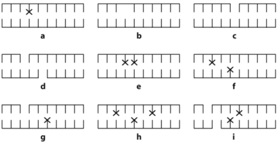
ionizing radiation:abase damage;bAP site;cSSB;dDSB from two close-by SSBs;etandem lesion;fclustered lesion with two damaged bases at opposite strands;gSSB with damaged base on opposite strand;hclustered lesion with three damaged bases;iclustered lesion with a DSB (from two closeby SSBs) and two damaged bases. Adapted from:[10]. . . 4 1.4 Diagram descibing how LEPTS processes a radiation-matter interaction event.
Adapted from:[23] . . . 6 1.5 The nucleobases: a- Uracil,b- 5-fluorouracil,c- 5-chlorouracil,d- 5-bromouracil. 9 1.6 Structure of the halothane molecule. Adapted from [42]. Atom colors mean: F
-light green; Cl - green; Br - red; C- black; H - white. . . 10
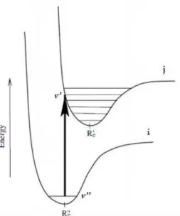
2.1 Vertical transition from the v”th vibrational level of the ith electronic state to the v’th vibrational level of the jth electronic state.R′
e corresponds to the
equilibrium internuclear distance. . . 15 2.2 For an inelastic collision the electronic incident momentum is−→k, the electronic
scattered momentum is−→k′,θis the scattering angle and−K→
ijis the transferred
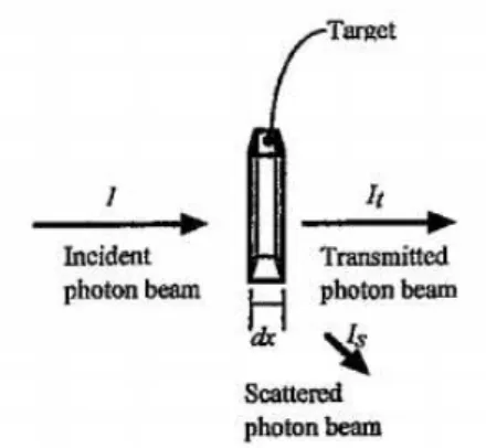
momentum to the target. . . 17 2.3 Possible light interactions with target sample.Idesignates the incident photon
beam intensity, Isdesignates the scattered photon beam intensity andItis the
transmitted photon beam intensity. The target has thicknessdx. Adapted from: [46]. . . 18
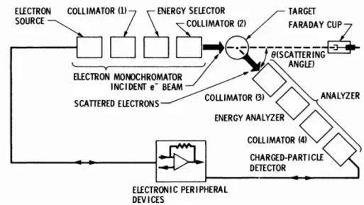
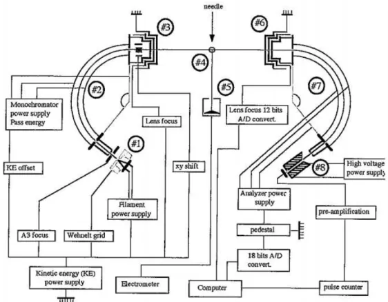
3.1 Basic components of an electron scattering spectrometer: electron monochro-mator, target, analyzer and electronic devices. Adapted from: [48]. . . 22 3.2 Scheme of the electron energy loss spectrometer. 1 - Electron Source; 2- Energy
selector; 3- Zoom lens of the energy selector; 4- Interaction region; 5- Faraday Cup; 6- Zoom lens of the analyzer; 7- Energy analyzer; 8- Detection device (channeltron). Adapted from: [46] . . . 23 3.3 Wehnelt-type electron source. Adpated from [48]. . . 23 3.4 Cross section of the electrostatic hemispheric analyzer. Adapted from [46] . . 24
LIST OFFIGURES
3.5 Geometric parameters of the electrostatic lenses. Adapted from [46]. . . 25 3.6 The collision region has a volume equal to the intersection between the incident
electron beam and the molecular beam inside the view cone of the analyzer. Adapted from: [52]. . . 26 3.7 The channeltron’s gain depends on the applied voltage. The arrow indicates
the optimal value of voltage to apply, in order to obtain the highest gain (∼2.4
kV). Adapted from: [46]. . . 27
4.1 HREEL spectra of halothane, CF3CHBrCl, recorded at 50 eV, 10◦ scattering angle, converted into differential oscilattor strength and normalized to the VUV spectra at 8.1 eV . . . 32 4.2 State resolved energy-loss by peak fitting the energy-loss peaks at 50eV and 10
◦scattering angle. . . . 34
4.3 Electron energy loss spectrum of halothane, CF3CHBrCl, at the incident energy of 10 eV and a scattering angle of 40◦. Then→σ∗transitions maxima are also labelled. See text for details. . . 35
6.1 a- Sevoflurane, b- Enflurane. Atom colors mean: F - light green; Cl - green; C-Black; H - white. . . 39
L
IST OF
T
ABLES
4.1 Calculated vertical excitation energies (EOM-CCSD/aug-cc-pVTZ + Rydberg level, CCSD/(PP)-cpVTZ geometry)(eV) and oscillator strengths compared with present experimental VUV absorption cross sections of halothane CF3CHBrCl [41]. . . 33 4.2 Experimental oscillator strength for the excitation bands of halothane, CF3CHBrCl. 34 4.3 Calculated vertical excitation energies(EOM-CCSD/cc-pVTZ,
CCSD/(PP)-cc-pVTZ geometry)(eV) and oscillator strengths for the lowest-lying singlet and triplet states of halothane CF3CHBrCl, without and with spin-orbit effects. [41] 36
A
CRONYMS
CEFITEC Centre of Physics and Technological Research.
DCS Differential cross section.
DSB Double strand break.
EEL Electron energy loss.
eV Electron-Volt.
FWHM Full-Width at half maximum.
HREELS High resolution electron energy loss spectroscopy.
LEE Low energy electrons.
LEPTS Low Energy Particle Track Simulation.
LUMO Lowest unoccupied molecular orbital.
MC Monte Carlo.
SSB Single strand break.
TEM Tissue Equivalent Material.
C
H A P T E R1
I
NTRODUCTION
1.1
Biological effects of radiation
In 2008 an estimated 12.7M new cases of cancer were diagnosed worldwide, i.e. today, cancer accounts for one in every eight deaths worldwide - more than HIV/AIDS, tu-berculosis, and malaria combined (Cancer Research UK and American Cancer Society). The number of patients needing radiotherapy treatments is increasing in modern society meaning an urgent need for advanced research in radiation biology and biophysics with the uttermost goal of developing new drugs and better attuned clinical protocols. This form of therapy can be external and employing electromagnetic radiation (X-rays orγ rays) or employing accelerated charged particles (e.g. electrons, protons or fast-neutrons) [1]. Internal radiotherapy or brachytherapy [2] makes use of radioactive seeds (radiation source) that are placed near the tissue requiring irradiation. In such cases the irradiated areas may be as reduced as possible and the secondary effects in the surrounding healthy tissues are to be minimized.
After the interaction of the ionising radiation with the biological environment, a set of different (bio-)physical/chemical processes are triggered and can be classified according to the time scale as schematically shown in figure 1.1. These (direct or indirect damaging) mechanisms are a result of different inter-linked stages that may result in mutagenesis and even formation of cancer. The first stage is the physical stage with processes occurring within a time scale of<10−15s, where mainly excitation and ionisation events occur as a
result of the incident radiation and where there is production of H2O+, H
2O*and radical species in local track regions.The products of these processes will eventually lead to other physico-chemical processes that in turn damage key biological units (e.g. DNA/RNA). As a consequence, a chain reaction of mechanisms and processes will eventually result in mutagenic effects in the physiological environment, with the final consequences being felt even as far as decades later in the form of cancer and other health problems.
CHAPTER 1. INTRODUCTION
Figure 1.1: Chronological diagram of radiation induced damage. Adapted from: [3]
Over the last decades, we have noticed a worldwide concerted effort in understanding the biological effects of radiation. In particular regarding in the detailed and compre-hensive knowledge of the underlying mechanisms of the direct and indirect action of high energy (keV to MeV) radiation with biological medium. When radiation interacts with biological medium (e.g. tissue), it will produce along its track several processes such as direct ionisation, with abundant secondary electrons (SE). These have an energy distribution below 20 eV and are produced at a rate of∼104/MeV of incident radiation. Secondary electrons are thermalized quickly (<10−15s) to subexcitation energies,
how-ever they can produce highly reactive species. On the other hand, the pioneering studies of Sanche and co-workers [4] [5] [6] have shown that subexcitation electrons can attach to DNA molecules and induce cell and tissue damages (at particular molecular sites of the nucleobases). Note that low energy electrons (LEE) are responsible for DNA damage and subsequent biological effects by direct and indirect action.
1.1.1 Direct and indirect action of radiation
Secondary electrons before being thermalized in the medium will lose energy through inelastic interactions such as ionisation, excitation, dissociation, among many others. SE can trigger other process including dissociative electron attachment, or hydrate in the medium and induce chemical changes [7]. Some of this processes can thus initiate the chain of events which results in radiation induced direct action. For example (see figure 1.2), in
1.1. BIOLOGICAL EFFECTS OF RADIATION
the vicinity of DNA (up to 2 nm), a secondary electron produced from an ionisation event from an incoming photon interaction with the physiological environment (e.g. water) may lead to DNA damage. In direct action mechanism, the radiation damage is induced by a secondary electron which results from the interaction of a photon with the physiological environment. In the indirect action mechanism, the secondary electron which results from the interaction of a photon with, the physiological environment, may interact with a water molecule and produce highly reactive products (e.g. H2O+, OH·).
Figure 1.2: Direct and indirect action mechanisms. Adapted from [8].
High energy photons or charged particles can interact with other cell constituents, namely water. Basically, the water molecule may become ionised. This reaction can be expressed as [8]:
H2O+hv−−→H2O++e− (1.1.1.1)
H2O+is a radical ion, with a short life-time (∼10−10s) and is highly reactive because it contains an unpaired electron. So, the H2O+ground state is a singlet state. Subsequently,
the ion radical (H2O+) reacts with a water molecule forming an hydronium ion and a
hydroxil radical [9] [8] [10]:
H2O++H
2O−−→H3O++OH· (1.1.1.2)
There are other reactions whose products are highly reactive. For example, an electronic ex-cited water molecule (H2O∗) releases energy either by autodetachment (losing an electron) or by molecular dissociation expressed as:
H2O∗ −−→H
2O++e− (1.1.1.3)
H2O∗ −−→H+OH (1.1.1.4)
Briefly, direct action induced damage is associated with reactions envolving directly the DNA strand by secondary electrons. Indirect action induced damage is associated with reactions involving deposition of energy in water molecules (and/or other biomolecules)
CHAPTER 1. INTRODUCTION
leading to a production of highly reactive radicals which may attack the DNA at specific sites. Indirect action induced damage is in fact responsible for two thirds of the damage of the genome in a cell, with the remaining one third of the damage is induced by direct action of high energy radiation [11]. Genome damage in a living cell may be a consequence of base damage, apyrimidmic/apurinic site, single-strand break (SSB), double-strand break (DSB), tandem lesions and various clustered lesions [10]. Not all lesions presents
Figure 1.3: Schematic representation of some types of DNA damage in dsDNA caused by ionizing radiation:abase damage;bAP site;c SSB;dDSB from two close-by SSBs; etandem lesion;fclustered lesion with two damaged bases at opposite strands;gSSB with damaged base on opposite strand;hclustered lesion with three damaged bases;i clustered lesion with a DSB (from two closeby SSBs) and two damaged bases. Adapted from:[10].
the same level of severity. SSB have minor consequences, because they can be repaired. Cluster lesions (DSB lesions in distant positions) can also be repaired. DSB in opposite positions or separated by a few number of bases yields the majority of biological effects.
1.1.2 Low-energy electrons
Secondary electrons with energy below 20 eV [12] are produced at large quantities (at rate of∼104/MeVof incident radiation [11]) and are responsible for the production of reactive products. Namely, when low-energy electrons react with a water molecule they will produce a unstable water anion. This anion can yield a one hydrogen radical and a hydroxil anion. This chain reaction is expressed as [10]:
e−+H
2O−−→H2O−∗ −−→H·+OH− (1.1.2.1)
The time frame of LEE interactions is ultra-fast (of the order of femtoseconds). Though the physical stage dominates with particular attention to excitation and ionisation processes. Moreover, the probability of occurring ionisation or excitation are similar, but the ionisation processes energy is larger than the excitation processes energy. Consequently, LEEs are the major responsible for transferring energy in the medium [12]. Though, in order to
1.1. BIOLOGICAL EFFECTS OF RADIATION
properly describe the effects of radiation right after irradiation in a biological environment (at a molecular level) we need a detailed knowledge and a comprehensive description of electron induced processes with such biomolecular targets.
The need to describe radiation effects at the molecular level, in other words, provides a nanoscopic description of radiation effects with key molecular targets within the biological environment. Unlike conventional dosimetry which is based on the amount of energy deposited per unit mass [13] here we have to refer to a micro and/or nanodosimetry description. In fact, micro and nanodosimetry have motivated research describing low-energy particle simulation [14] [15] [16] [17] [18] [19], since conventional dosimetry is not adequate to infer radiation effects at nano-scale, e.g, in the vicinity of DNA (up to 2nm). These are based on MC (Monte-Carlo) codes, namely Low Energy Particle Track Simulation (LEPTS) [20] [21].
1.1.3 LEPTS: Low Energy Particle Track Simulation
Several MC based simulations codes oriented towards radiotherapeutic and medical imaging applications have been developed and are well-implemented in hospital and clinical environments. The main goal of LEPTS is to provide a description of radiation interactions with biological medium at nano-scale as an attempt to address the radiation induced damage at molecular level. In other words, LEPTS aims to describe radiation effects in nanovolumes.
As previously discussed, the genotoxic effects of radiation can be generated by the products of water radiolysis, namely subexcitation electrons. Then, MC based codes in order to give a proper description of the induced genotoxic damage caused by radiation in biological tissue, have been improved in order to provide an accurately description of the events. In other words, this kind of models must include accurate descriptions of [22]:
• Different tissues such as muscle, bone, lung, etc.;
• Different radiation types: photons, electrons and heavy charged particles;
• Different energies ranges (∼1-10 000eV);
• Incident radiation geometries.
The main goal of Low-Energy Particle Track Simulation (LEPTS) is to provide inter-action details at the nano-scale as an attempt to address the radiation induced damage at molecular level. However, in order to accomplish the latter goal there is still a great lack of data and research studies. LEPTS is a tool for nanodosimetry (a procedure to quantify radiation damage in nanovolumes) which gives a molecular-level description of radiation transport and energy degradation down to about 1 eV inherent processes. Since, conventional dosimetry (amount of absorved energy per mass unit) is not suitable to infer radiation effects a nano-scale, for example at DNA vicinity (up to 2nm).
CHAPTER 1. INTRODUCTION
MC based models should be improved in the following aspects in order to give a realistic description of the effective genotoxic damage caused by the incident radiation in a biological tissue [23]:
• The simulation has to take into account the molecular nature of the absorber medium in order to predict the physical and/or chemical alterations actually induced in its components.
• All different kinds of known inelastic collisions have to be considered in the interac-tion model instead of restricting events to ionisainterac-tions only.
• Low-energy electrons cannot be ignored by the interaction by applying a cut-off value. The code should simulate the electron track until thermalization in order to include scattering events that occur only at low energies, including subionisation energies.
1.1.3.1 Programme Structure
LEPTS is a general purpose code written in C++ that combines its own routines with existing MC programmes like GEANT4 and PENELOPE [21] [24], which can be used for expanding the energy range upwards or for simulating other types of radiation.
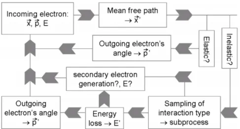
LEPTS simulates each interaction event (collision) individually starting with the initial conditions (positions, direction and energy) of the incident particle and giving as an output its new coordinates and energy loss. Figure 1.4 shows a diagram which describes how LEPTS processes a radiation-matter interaction event. In other words, the programme
Figure 1.4: Diagram descibing how LEPTS processes a radiation-matter interaction event. Adapted from:[23]
calculates the scattering angle and the particle’s energy loss specifically according to the corresponding distribution functions (differential cross sections (DCS) and energy loss spectra). If ionisation occurs, a secondary electron (outgoing particle) is tracked. The
1.1. BIOLOGICAL EFFECTS OF RADIATION
secondary electron is generated and enters the simulation process with its energy and direction calculated by applying energy and linear momentum conservation laws. This particle is tracked until its thermalization with the surrounding material, at which point it transfers the remaining energy. All particles, including any secondary particles produced are always followed by the same means as primary particles until their absorption or thermalisation.
The interaction model used by LEPTS distinguishes two classes of scattering events: elastic and inelastic scattering. For elastic collisions, since no energy is deposited in the medium, the programme calculates the particle’s scattering angle according to the distribution established by the corresponding differential cross sections (DCS). For inelastic collisions, different subprocesses can occur with their relative frequency according with partial cross sections depending on particle’s energy and molecular species encountered. For electron scattering, these processes can currently include ionisation, vibrational and rotational excitation, electronic excitation, neutral dissociation and dissociative attachment. Once more, these processes relative frequency are a function of the particle’s energy and molecular species encountered.
The interaction event is terminated when all secondary electrons have lost all of their energy or had left the simulated volume. After simulation, the user is provided with 3D maps of all interaction events produced in the particle’s track, together with energy information about the corresponding incident energy, energy deposition, particle type, type of interaction, etc. [20]
Note that LEPTS can also simulate positrons interactions andbremmstrahlung produc-tion is despicable, because the programme focuses on low-energy interacproduc-tion.
1.1.3.2 Input information
As LEPTS is a MC based simulation code focused in low-energy interactions and is necessary to collect low-energy electron (and positron) interaction data in materials of biomedical relevance. In order to achieve more accurate descriptions of molecular-level mechanisms, it is required to supply for each molecular component and incident parti-cle three categories of input information: integral scattering cross sections, energy loss distributions functions and angular differential cross sections. Input parameters can be experimental data and/or theoretical data for energies in the range 1-10 000 eV. However, preference is given to experimental results. Theoretical results are used if there are no conclusive experimental results. Hence, new input parameters concerning low energy interactions are urgently needed and should be generated experimentally.
With reference to CS data, in the last years several studies have been performed [25] [26] [27] if we consider that the biological environment is mainly described by a composition of water or even by a set of chemical compounds that ultimately can be used as tissue equivalent materials (TEM). However only few can be used as input data in biomedical applications [28] [29]. CS of simple target molecules such as water [28], methane [29]
CHAPTER 1. INTRODUCTION
or pyrazines [30] have been obtained and used in trial experiments as input data for simulations. Molecular targets that combines atoms such as H, C, N, O and P can be used as tissue equivalent material. TEM are substances that upon radiation interactions, namely absorbing and scattering properties, can match those of a relevant biological medium [31].
1.1.4 Energy Loss Distribution Functions:
Energy loss distributions functions are a critical parameter as an input. In order to correctly simulate the particle’s track, it will be required to know the energy transferred in every interaction or event. In other words, LEPTS receives as input an electron (and/or a positron) energy loss spectra obtained experimentally, when available [13] [7]. From the electron energy loss spectra the mean excitation energy or average excitation energy,E, of the target can be calculated. The collision stopping power can be calculated from the mean excitation energy,E, and the integral inelastic cross section,σinel. First, the collision
stopping power is defined as the average energy loss per unit path length due to inelastic collisions with the bound electrons of the medium. Then, assuming an homogeneous target of molecular densityN[13] [32] [33], the collision stopping power can be calculated by: − dE dx col
= N
∑
n
Enσn (1.1.4.1)
In the equation 1.1.4.1, n is the number of accessible excited states. Although, if we assumed an average excitation energy, the collision stopping power can be expressed as [13] [32] [33]:
−1 ρ dE dx col
= Na
MEσinel (1.1.4.2)
Whereρ is the target density in the collision volume, Na is the Avogadro number and
Mis the molar mass. Finally, the mean excitation energy or average excitation energy,E
can be calculated from the corresponding energy loss spectra, regarded as a distribution probability function, as follows [13] [32] [33]:
E= RE0
0 I(E)EdE RE0
0 I(E)dE
(1.1.4.3)
WhereE0is the incident energy and I(E)is the electron intensity for a given energy loss.
1.1.5 Low-energy electrons in Chemoradiation Therapy - CRT
Low-energy electrons are able to induce SSB and DSB in DNA/RNA, which may corre-spond to severe structural changes that ultimately may lead to loss of integrity of such key structures. LEE are the major responsible for radiation damage, because their creation rate is large and they have a short range in the biological medium [14]. So, within a nanoscopic point of view, LEE are able to spread the radiation energy and to largely increase the radiation dose. Léon Sanche has reported that "controlling the local density of LEE and
1.2. HALOTHANE
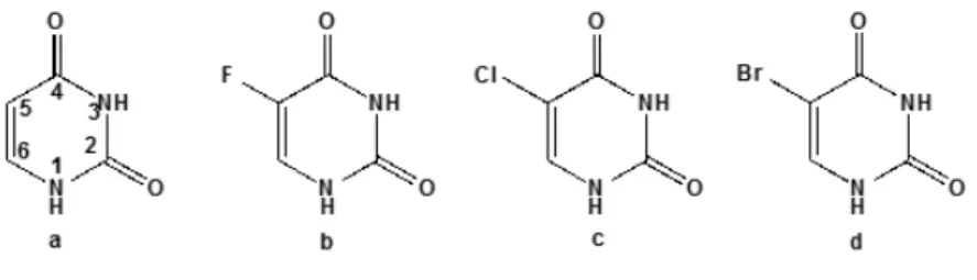
the reactions they induced should result in the control, within a short range, of a large amount of the energy deposited by high energy radiation in cells"[22]. Though LEE can be used to increase radiosensitization of DNA. Briefly, if there is an increase on the sensitivity of the DNA to LEE, then the DNA should become more radiosensitive. This is accomplished by amplifying the DNA-LEE interaction. Chemoradiation therapy consists in the treatment of cancer with chemotherapy and high energy radiation [22]. Over the last years several clinical studies with 5-fluorouracil and cisplatin have been performed. The treated patients with these agents showed increased survival as compared to other treatments. Halouracils, such as 5-bromouracil and 5-chlorouracil, have been proposed as radiosensitizers. These molecules result from the substitution of a hydrogen group in theC5position of the uracil molecule for an halogen atom (see figure 1.5). This replacement leads to a higher dissocia-tion yield of DNA and subsequent increase of apoptosis (cell death) rate [18] [3] [34] [35]. Before the irradiation, the halogen atom does not change the biological properties of DNA , i. e. there is no change in the gene expression. As far as we are aware, there are no studies in the literature regarding simulation of low-energy electrons with radiosensitiziers in par-ticle track codes. Hence, there is an urgent need for radiosensitiziers equivalent materials. At this time, LEPTS is not able to predict damage in biological medium at the molecular level. In fact, the majority of biological medium simulations are performed using gaseous or liquid water [7] and more recently with pyrimidine [7]. So, we propose halothane, CF3CHBrCl, as an underlying molecular constituent for describing radiation damage in cancerous tissue in the concomitant chemoradiation therapy. Because, halothane is a larger molecule that contains halogens, carbons and hydrogen atoms, can be used in order to better understand the role of halogens in biological constituents.
Figure 1.5: The nucleobases: a- Uracil,b- 5-fluorouracil,c- 5-chlorouracil,d- 5-bromouracil.
1.2
Halothane
Halothane (CF3CHBrCl, 2-bromo-2-chloro-1,1,1-trifluoroethane) is a halogenated hydro-carbon non-flammable that is extensively used as an anaesthetic by inhalation to induce and keep anaesthesia. It reduces the arterial pressure and decreases heart rate. The total number of inhalation anaesthetics has been suggested a worldwide used 10 kylotons/year
CHAPTER 1. INTRODUCTION
(mainly in developed countries)[36], where more than 80 % is exhaled unchanged by the patient [37]. In other words, halothane as an halogenated hydrocarbon has a considerable global-warning potential. It is known that the ozone layer is damaged by chlorine and bromine containing compounds called, e.g. CFC) (chlorofluorocarbons). Note that anaes-thetic gases such as halothane are used in medicine without restrictions. The vacuum ultraviolet photoabsorption spectrum has been studied by Dumas et al. [38], Langbein et al. [37], Bilde et al. [39], Orkin et al. [40], and more recently Ferreira da Silva and co-workers [41], reporting absolute values from high-resolution photoabsoprtion studies in the energy range of 4.0–10.8 eV (310–115 nm). In the latter work special attention was devoted to provide a systematic assignment of the spectral features. Moreover, such contribution addressed for the first time a combined set of different levels of theory to fully support the spectral features in the valence, Rydberg and lowest ionic states. As far as we are aware there have been no attempts to experimentally determine the low-lying triplet states which are of extremely relevance regarding the low-energy electronic state spectroscopy of a molecule. These play a crucial role as local states to contribute to the lowest yields of molecular degradation.
The sample of CF3CHBrCl was purchased from Sigma Aldrich with quoted purity of
≥99 %. The sample was degassed by repeated freeze-pump-thaw cycles prior to use.
Figure 1.6: Structure of the halothane molecule. Adapted from [42]. Atom colors mean: F -light green; Cl - green; Br - red; C- black; H - white.
1.2.1 Structure and properties of Halothane
Theoretical studies have shown that the staggered conformer of halothane is more sta-ble than the eclipsed conformer [43] [44]. Halothane has symmetryC1in the electronic ground state. The symmetry class available to a C1 molecule is A and the calculated electron configuration of the outermost valence orbitals of the X1A ground state is ...(41a)2(42a)2(43a)2(44a)2(45a)2(46a)2[41]. The highest occupied molecular orbital (HOMO)
1.2. HALOTHANE
and the second highest occupied molecular orbital (HOMO-1) have Br 4p lone pair char-acter, whereas the HOMO-2 (44a) and HOMO-3 (43a) have Cl 3p lone pair characters. The lowest unoccupied molecular orbitals, 47a (LUMO) and 48a (LUMO+1) are mainly of σ∗(C−Br)andσ∗(C−Cl)antibonding character [41]. In addition, the calculated triplet transitions have shown very weak oscillator strengths (< 0.0001), resulting in 10 and almost 100 times lower for “Br” and “Cl”, respectively, than the corresponding singlet transitions [41]. These results will be particularly relevant when assessing the nature of the underlying transitions as discussed below.
1.2.2 Chemical and Physical properties:
Boiling Point:50,2◦C (at 101,325 kPa); Density:1,868 g/cm3;
Molar Mass:197,4 g/mol. [42]
1.2.3 Safety and Hazards:
Exposure routes:The substance can be absorbed into the body by inhalation of its vapours, by ingestion, by skin and/or eye contact.
Symptoms:Eye, skin and respiratory system irritation, confusion, nauseas, somnolence, dizziness, analgesia and anesthesia. Cardiac arrhythmia. Liver and kidneys damages. Decreased audio-visual performance.
Target Organs: Eyes, skin, respiratory system, cardiovascular system, central nervous system, liver, kidneys, reproductive system.
Effects of Short Term Exposure:The substance is irritating to the eyes. The substance may cause effects on the central nervous system and cardiovascular system. Exposure at high levels can cause unconsciousness.
Effects of Long Term Exposure:The substance defats the skin, which may cause dry-ness or cracking. The substance may have effects on the liver. This may result in liver impairment. Animal tests show that this substance possibly causes toxicity to human reproduction or development. [42]
CHAPTER 1. INTRODUCTION
1.3
Thesis Objectives and Outline
This work aims to obtain the first set of energy loss distribution function under electric dipole favoured conditions and experimental evidence of the low-lying triplet states for halothane. The results will be used as input parameter in MC based simulation code, namely LEPTS. The High-Resolution electron energy loss spectrometer (HREELS) set-up at CEFITEC, unique in Europe for gas phase experiments in the electron energy range from a few eV up to 100 eV will be effectively used to produce essential set of data for dose planning in radiotherapy [45].
This thesis is organized in six chapters, including the present one.
Chapter 2 is about the general principles, laws and models related with molecular spectroscopy. In other words, this chapter is the basis used to analyse and interpret the experimental results.
Chapter 3 is about the experimental setup, namely the VG-SEELS 400. Briefly, in this chapter it is explained how to use the experimental set-up and its operating modes.
Chapter 4 is dedicated to the experimental results obtained in this work. Which are are divided in two parts. The first part is about the dipolar conditions measurements and the second part experimental evidence of low-lying triplet states of halothane.
Chapter 5 presents the general conclusions.
The last, chapter 6 discusses the future work and further studies regarding HREELS and halothane.
C
H
A
P
T
E
R
2
M
OLECULAR
S
PECTROSCOPY
Molecular spectroscopy consists in the study of transitions between different electronic (and ro-vibrational) states of molecules following the absorption of particular amounts of energy. This chapter is divided in two sections. The first is about electronic collisions and the second is about photoabsorption.
2.1
Born-Oppenheimer approximation
The Born-Oppenheimer approximation is the assumption that the nuclear motion can be separated from the electronic motion. Hence, the molecular wave function,ψcan be separated into two parts describing, respectively, the electronic,ψe, and nuclear motion,
ψN [46]:
ψ=ψeψN (2.1.0.1)
Whereψeis the electronic motion wave function andψN is the nuclear motion wave
function. This approximation relies on the great differences between the electronic motion velocity and the nuclear motion velocity. Electrons are viewed as moving in the field of fixed nuclei. The vibrational and rotational motions of the nuclei have different periods and energies associated. Then, another approximation consists in separating the nuclear motions into its different components:
ψ= ψeψNvψNR (2.1.0.2) WhereψNv refers to the nuclear vibrational motion wavefuction andψNR refers to the nuclear rotational motion wavefunction. Therefore, the molecular state is characterized by its electronic, vibrational and rotational states and the energy related to which state can be estimated according to the Born-Oppenheimer approximation. So, the total energy of the
CHAPTER 2. MOLECULAR SPECTROSCOPY
molecular state is the summed contribution of each of them [47]:
Et =ENR+ENv+Ee (2.1.0.3) In this work, the rotational motions are not considered, because the experimental set-up resolution is not enough to resolve such contributions.
2.2
Franck-Condon Principle
When a molecule absorbs energy it can lead to electronic transitions. The Franck-Condon principle states that when a molecule changes its electronic state, the molecular geometry is preserved. So, the internuclear distance and the velocity of the nuclei is conserved. Such processes are described as vertical transitions. The probability of occurring a vertical transition is defined by the Franck-Condon overlap integral. In other words, a transition between two statesi→ jhas an associated probability proportional to the dipolar moment mean value, expressed as [46] [47]:
di,j =
Z
ψi~dˆψjdV = D
ψj d~ˆ
ψi E (2.2.0.4) And, ˆ ~
d=−e~r (2.2.0.5)
In the last two equations,ψiandψjare the initial and final wave functions, respectively,
ˆ
~
dis the dipolar moment operator which depends on the electric chargeeand the distance between charges,~r. Applying the Born-Oppenheimer approximation, the wave function
of thei,jstates is separable into its different components, given by:
ψ(~r,~R) =ψe(~r,~R)ψn
ε,v(~r,~R) (2.2.0.6)
Whereεis the electronic state. In this case,ε=i,j. And,vis the associated vibrational state. In this case,v =v′′,v′.
Replacing in equation 2.2.0.4:
Z
ψe(~r,~R)ψin,v′′(~r,~R)d~ˆψe(~r,~R)ψjn,v′(~r,~R)dV (2.2.0.7)
The mean dipolar moment amplitude is defined as:
Z
ψie(~r)d~ˆψej(~r)dV =Dψej(~r)
~dˆ
ψei(~r)E (2.2.0.8)
Which is independent of the internuclear distance~R. Finally, the transition probability
is given by:
Pi→j = dei,j
2· Z
ψn(i,v′′)ψn(f,v′)dV
(2.2.0.9)
WherePi→j is the probability of transition from thev′′th vibrational level of theith
electronic state to thev′th vibrational level of thejth electronic state.
2.3. ELECTRONIC COLLISIONS
Figure 2.1: Vertical transition from the v”th vibrational level of the ith electronic state to the v’thvibrational level of the jthelectronic state.R′
ecorresponds to the equilibrium
internuclear distance.
2.3
Electronic Collisions
When a free electron collides with molecules several processes can occur. Kinetically, these processes are categorized into two classes: elastic scattering and inelastic scattering. Electron attachment, which is a process that may lead to molecular fragmentation [46] [48], but will not be thoroughly discussed here since it is not the main scope of this work.
ELASTICSCATTERING:e(Ei) +M −→M+e(Er,θ),Er=Ei
In this kind of collisions, the electron’s energy loss is despicable. The electron loses some energy due to the momentum transfer, however the energy lost is proportional to the ratio between the mass of the electron and the mass of the molecule. Then it is considered that energy transferred is very reduced towards energy lost to excitation of internal molecular degrees of freedom (with the exception of rotation).
INELASTICSCATTERING:e(Ei) +M −→M∗+e(Er,θ),Er< Ei
This kind of collisions occur when the electron loses a portion of its kinetic energy to excitation of internal molecular degrees of freedom. A certain amount of energy is lost by the electrons,El, and transfered to excitation of the target molecules. In other words,
excitation energy,En, is equal to the energy loss,El, [46]:
En =El (2.3.0.10)
By energy conservation:
Ei =Er+El (2.3.0.11)
WhereinMdesignates the target molecule,edesignates the electron,M∗indicates that the molecule is in a rotational, vibrational and/or electronic excited state,Eicorresponds
to the electron impact energy,Ercorresponds to the residual energy of the electron.
CHAPTER 2. MOLECULAR SPECTROSCOPY
2.3.1 Scattering Cross Section
Assume that a beam ofNelectron per second collides on a molecular target consisting of
NMmolecules (at low density). The number of electrons deflectedNdper second by the
molecules, into a solid angledΩ, defined by polar anglesθeφis given by [46] [48]:
Nd =NMNddΩσ(E0,θ,φ)dΩ (2.3.1.1)
E0is the kinetic energy of the electrons anddΩ=sin(θ)dθdφ The quantity dσ
dΩ(E0,θ,φ)has dimensions of area per unit solid angle and is designated
differential cross section (DCS) for the elastic or inelastic process. However, for an inelastic scattering process the DCS represents the excitation differential cross section of the target from an initial statejto a final statej′. In this particular case, the target is gaseous then the molecule freely rotates and the cross section becomes independent of the azimuthal polar angleφ. The total number of particles per second elastically scattered from an incident beam of unit flux and energyE0is obtained by integrating the differential cross section over all polar angles. This integration yields the integral cross section (ICS) which is defined by [48]:
σ(E0) =2π
Z π
0
dσ
dΩ(E0,θ)sin(θ)dθ (2.3.1.2) The introduced definitions are applicable only to "ideal" measurements of electron-molecule collision events. In practice, electron-impact cross sections are measured for an ensemble of target molecules with instruments of finite energy and angular resolutions and represent averages over ensemble and the instrumental ranges of the parameters. Furthermore, with the exception of H2and other homopolar diatomic molecules, rotational excitation (and in some cases even vibrational excitation) cannot be decoupled from elastic scattering. Thus, the measured elastic DCS is represented by:
DCS(E0,θ) = dσ(dE0,θ)
θ =
∑
j∑
j′Njσ(E0;θ;j→ j′) (2.3.1.3)
Wherejandj′are the initial and final rotational state quantum numbers, respectively, and
Njis the population fraction of the statej.
For an inelastic collision there is a momentum transfer from the electron to the target. The differential cross is a function of the incident electron momentum,−→k , the scattered electron momentum,−→k′ and the scattering amplitude f
ij(θ,φ). The momentum transferred
is−K→ij.
dσij
dΩ =
−→k
−→k′
fij(θ,φ)2 (2.3.1.4)
2.3. ELECTRONIC COLLISIONS
Figure 2.2: For an inelastic collision the electronic incident momentum is−→k , the electronic scattered momentum is−→k′,θis the scattering angle and−K→
ijis the transferred momentum
to the target.
For an electric dipole transition, the differential cross section is:
dσijd
dΩ ∝
−→k ′
−→k
ε2ij,1
−→Kij
2
(2.3.1.5)
The spin forbidden transition differential cross section was reported by Dillon [49] for the Helium atom:
dσijT
dΩ ∝
−→k ′
−→k
5
εij,2(−→Kij)
2 (2.3.1.6)
Where σijd is the electric dipole transition differential cross section and σijT is the spin forbidden transition differential cross section.εij,1is the electric dipole matrix element and εij,2is the spin forbidden matrix element.
CHAPTER 2. MOLECULAR SPECTROSCOPY
2.4
Selection Rules
For electron impact experiments under particular constrains, the probability of occurring electric dipole forbidden transitions is higher than for photoabsorption. From the experi-mental point of view, it is possible to express the relationship between cross section and momentum transfer as a function of electron impact energy and scattering angle [46] [48]:
• If the impact energy is relatively high (∼100 eV) and the scattering angle is small
(θ ∼ 0) then spin and symmetry allowed transitions are favoured. Momentum
transfer is small and electrons excite the target as photons do. This fact is verified, because the electron energy loss spectrum acquired in such conditions and the photoabsorption spectrum are similar. Thereby, it is possible to use electrons under particular experimental conditions to mimic photons to determine photoabsorption cross sections. [48]
• If the impact energy is high or intermediate, symmetry forbidden transitions are favored at high scattering angles in detriment to allowed symmetry transitions.
• If the impact energy is low (slow electrons) and the scattering angle is high, spin forbidden transitions are magnified relatively to spin allowed transitions. Selection rules for dipole transitions do not apply.
2.5
Photon-molecule interaction: Photoabsorption
In an attenuation experiment, when electromagnetic radiation passes through a static gas sample several interactions can occur. Namely, Rayleigh scattering, Thomson scattering and Raman scattering. Basically, light can be transmitted, scattered or absorbed (see figure 2.3) [46]. In this work context, the most relevant interaction is photoabsorption. Briefly,
Figure 2.3: Possible light interactions with target sample.I designates the incident photon beam intensity, Isdesignates the scattered photon beam intensity andItis the transmitted
photon beam intensity. The target has thicknessdx. Adapted from: [46].
an incident photon flux is sent onto a target of given area, thickness and filled with a molecular densitynof the sample gas (absorber). The absorption of photons by the target
2.5. PHOTON-MOLECULE INTERACTION: PHOTOABSORPTION
results in the transitioni→jand consequently the molecular density of the gas decreases
to the reduction of the number of absorber particles [46].
Absolute photoabsorption cross sections are a macroscopic quantity related to light intensity attenuation. It can be obtained using the Beer-Lambert law [50]:
It= I0e−nσx (2.5.0.7)
WhereItis the radiation intensity transmitted through the gas sample,I0is the incident radiation intensity,ndesignates the molecular number density of the sample gas,σis the absolute photoabsorption cross section andxis the absorption path length.
2.5.1 Relation between Electron Impact spectra and VUV Photoabsorption
spectra
If the HREELS spectra is obtained with relative high incident electron energy (> 50 eV) and a small scattering angle (∼0◦), the electric dipole transitions are favoured. In other words,
it is possible to use electrons as photons to determine photoabsorption cross sections. In fact, it is possible to convert electron impact measurements under certain experimental conditions to establish optical oscillator strengths. This is out of the work and will be no further explored. In brief, the inelastic scattered intensity is converted to a relative differential oscillator strength distribution using the following equations [46] [51]:
d f
dE ∝ I(E)
ln
1+ θˆ
γ
!2
−1 (2.5.1.1) And,
γ2 ≈
E
2T
2 1− E
T
−1
(2.5.1.2)
Where T is the incident electron energy, E is the electron energy loss, I(E)is the scattered electron intensity and ˆθis the spectrometer angular acceptance (1.25◦±0.25). In
order to obtain absolute differential cross sections it is necessary to normalize the measured HREELS spectra to an absolute measured spectra, for instance a VUV photoabsorption spectra.
σ(E) = hπq
2
mec
d f
dE ⇔σ(E) =109, 75 d f
dE (2.5.1.3)
Where σ(E)is in Mb and dEd f is in eV−1. Comparison of the HREELS cross section values with those recorded using the synchrotron source provides a test for any systematic error in the optical values arising from the line saturation effect and second-order light from the light source and beam line [51] [41].
C
H
A
P
T
E
R
3
E
XPERIMENTAL
M
ETHODS
In this study it was used an high resolution electron energy loss spectrometer - VG SEELS 400 - to study the halothane electronic states. This chapter aims to describe HREELS spectrometer and the underlying experimental methods.
The equipment employed to study the electronic scattering by molecules is designated electron scattering spectrometer. A spectrometer consists of several components. An electron source, an electron monochromator, an electron energy analyser, a target and peripherals electronic devices (see figure 3.1). Electron collimation, transport and energy selection are achieved by electrostatic techniques and the vacuum chamber is lined with magnetic shielding material in order to reduce the magnetic field intensity to a few miliGauss along the electron path and in the scattering region. [46] [48].
3.1
Equipment Description: Vacuum Generator SEELS 400
The host research centre Atomic and Molecular Collisions Laboratory at the Centre of Physics and Technological Research - CEFITEC - provides a HREELS equipment, VG-SEELS 400, modified for gas phase measurements as represented in figure 3.2.
An hemispheric 150 ◦electrostatic monochromator equipped with a three element lens defines the electron beam energy in order to be equal to the desired impact energy. The lens focus the electron beam into the collision region. The electron beam typical current ranges from 5×10⁻¹⁰A to 10×10−10A, as it can be measured by the Faraday cup
assembled on the spectrometer. The electron beam intersects the target beam (gas) which flows through a 1 mm diameter needle, at 90◦. The analyzer system is of the same type as the monochromator rotatable from∼5◦to +120◦around the positive direction. Both
electron energy selectors work in the constant pass-energy mode. The scattered electrons signal is detected by an electron multiplier of the channeltron type. The residual pressure
CHAPTER 3. EXPERIMENTAL METHODS
Figure 3.1: Basic components of an electron scattering spectrometer: electron monochro-mator, target, analyzer and electronic devices. Adapted from: [48].
is about 1×10⁻⁷mbar and when the gas is admitted the pressures rises to 1−1.5×10⁻⁵
mbar. The resolution measured at the FWHM of the elastically scattered electrons elastic peak is typically within 50 and 100 meV. The elastic peak corresponds to the electrons with zero energy loss and it is used to determine differential cross sections. The electron impact energy working range varies from 5 to 100 eV. In essence, the equipment allows the detection of scattered electrons matching different momenta with high energy resolution [48] [45].
3.1.1 Electron Source
The electron source produces an electronic beam that is transported to the target by two collimators and one energy selector. This element is designed to generate a maximum electron current with minimum angular divergence. The main component of the electron source is the electron emitter. The electron emitter is a v-shaped tungsten filament. A current between 2 and 3 A heats the filament which results in the emission of electrons by thermoionic effect. The thermoionic effect is usually used as source of electrons. Briefly, this effect occurs when a metal is heated to a sufficiently high temperature, and free electrons are produced with an energy distribution given by [48]:
dN(E)∝exp
−W+E kT
dE (3.1.1.1)
dN(E)is the number of electrons emitted per second with energies betweenEandE+dE,
k is the Boltzmann constant, T is the absolute temperature and W is the metal work function. Pure metals need to be heated to about 2000 K for electron emission. This fact is disadvantageous, because the produced electrons have a broad energy width (∼0.5
eV) and the heat dissipation is unwanted. The electron source is aWehnelt-type. This kind of source utilizes aWehneltcylinder and an anode in order to extract electrons from the
3.1. EQUIPMENT DESCRIPTION: VACUUM GENERATOR SEELS 400
Figure 3.2: Scheme of the electron energy loss spectrometer. 1 - Electron Source; 2- Energy selector; 3- Zoom lens of the energy selector; 4- Interaction region; 5- Faraday Cup; 6-Zoom lens of the analyzer; 7- Energy analyzer; 8- Detection device (channeltron). Adapted from: [46]
filament. The v-shaped tungsten filament is placed inside aWehnelt cylinder. When a current passes through the filament, is heated and electrons are emitted by thermoionic effect and a variable tension (negative relatively to the filament) is applied on theWehnelt
cylinder resulting in the formation of an electron cloud. The hole in the cylinder forms the shape of the electron beam. The beam intensity is controlled by the variable tension applied on theWehneltcylinder. The electron cloud around the filament presents several advantages, such as the reduction of the effects caused by irregularities of the filament surface and the temperature variation on the filament.
Figure 3.3: Wehnelt-type electron source. Adpated from [48].
CHAPTER 3. EXPERIMENTAL METHODS
3.1.2 Monochromator
The electron monochromator produces an electronic beam with angular divergence and well-defined energy. The main components of the electrons monochromator are the elec-tron source, the collimator and the energy selector. The elecelec-tronic beam energy range is large (∼0.5 eV FWHM). It is focused into the energy selector entrance slit by theWehnelt
grid and by the A3 focus lens (collimator 1 of the spectrometer). A hemispherical energy selector is used in order to increase the resolution up to the energy resolution needed (∼
50-100 meV) to study elastic or inelastic scattering from molecules. The device is formed by a pair of spherical electrodes that have a dihedral angle of 150◦and separated by 9.5 mm. The entrance and exit slits are diametrically opposed. The mean radius,r0is 50 mm. The pass energyE0is defined by a constant voltage (Vp) applied on the electrodes [46]:
E0 = qVp
b a− ab
(3.1.2.1)
Whereqis the electronic charge,aandbare the inner and outer radius.
Figure 3.4: Cross section of the electrostatic hemispheric analyzer. Adapted from [46]
The energy resolution,∆E, measured at the FWHM of the outgoing electronic distribu-tion is given by [46]:
∆E E0 =
∆S
2r0 + 1
4α2 (3.1.2.2)
Where αdesignates the semi-angular divergence of the incoming beam and ∆S is the entrance slit width. The outgoing electrons are deflected by two pairs of plates that centre the beam onto the target (xy shift). The entrance slit is polarized to aV0potential, in order to accelerate the electrons to a certain pass energy. The sameV0potential is also applied to the exit slit and to the first element of the lens. Hence, the incident energy of electrons,Ei
is given by [46]:
Ei =qV0+E0+C (3.1.2.3) WhereCis a constant which depends on the surface potentials and the thermal energy of the electrons emitted by the filament. A heating device is fixed on the selector and maintains it to approximately 150◦C, in order to reduce the adsorption of the gas target molecule on the surfaces and consequently avoid creating surface potentials. By invert-ing the monochromator electrodes polarity, the enterinvert-ing beam is deflected on the outer
3.1. EQUIPMENT DESCRIPTION: VACUUM GENERATOR SEELS 400
spherical electrode allowing the measurement of the incoming electrons current. Tipically, for an emission current of 5×10⁻⁶A, a current of 5×10⁻⁸A is measured. The electrons
extracted from the electron source are collimated and focused into the energy selector entrance slit by a collimator with a desired divergence angle. The collimator is formed by two electrostatic lenses. The first lens accelerates the electrons and the second lens slows down and focus the beam into the selector entrance slit.
3.1.3 Monochromator zoom lens
The electrostatic lens is formed by three elements and is used to focus the electron beam into the target (collimator 2 of the spectrometer). Focusing of an electron beam is achieved by passing it from one region to another with different constant electrostatic potentials applied between the electrodes. The properties of the electrostatic lenses are defined by geometric parameters (A,D,T) and the applied potentials (V1,V2,V3) on the lenses elements (see 3.5).
Figure 3.5: Geometric parameters of the electrostatic lenses. Adapted from [46].
The lens is designated as asymmetric voltage lens when the potentialsV1,V2andV3 are different. A particular kind of asymmetric potential lenses are zoom lenses. Zoom lenses in electron optics have the property that with an object of fixed position and energy, the energy of the image can be varied whilst its position remains constant. The ratio V2
V1
controls the focusing strength whilst the ratio V3
V1 is used to change the energy of the image
point. AsV1has the same potential as the monochromator slit (V0) and the third element is grounded (V3= 0 V), the energy of the image is not changed. The tuning ofV2optimizes focusing of the electron beam into the collision region where it interacts with the target beam. In the energy analyser there is also a three element electrostatic lens that focus the scattered electrons into the entrance slit of the energy selector.
3.1.4 Collision Region
The collision region is where the monoenergetic electron beam intersects the target beam. This region is delimited by a molybdenum cylinder perfurated by a circular slit. In the centre, a 1 mm stainless steel needle introduces the gas beam. The needle, the Mo cylinder
CHAPTER 3. EXPERIMENTAL METHODS
Figure 3.6: The collision region has a volume equal to the intersection between the incident electron beam and the molecular beam inside the view cone of the analyzer. Adapted from: [52].
and the outer element of the zoom lenses (mounted on the monochromator and the analyzer) are all grounded.
3.1.5 Faraday Cup
The Faraday cup is a device used to measure the electron current transmitted through the interaction region. It is assembled on the same rotatable plate as the analyzer, which allows positioning it in front of the transmitted beam. The collector is polarized by a stabilized power supply and connected to an electrometer. A typical current value measured is about 10−10A.
3.1.6 Analyzer
The scattered electrons at angleθare energetically analysed using analyser, identical to the monochromator and of 1.25◦angular acceptance. The scattered electrons are focused into the entrance slit of the analyzer by a zoom lens. The third element of the lens is at the same potential,Vret, as the entrance slit of the analyzer. Hence, the allowed electrons to
enter the selector must have residual energy –Er:
Er=Ei−El ≥qVret (3.1.6.1)
WhereEiis the initial or impact energy of the electrons before collision andElis the energy
lost in an inelastic collision. Assuming an optimal tuning of the analyser lensV2potential, the condition for an electron to be focused onto the analyser exit slit is:
Er =E0+qVret (3.1.6.2)
WhereE0is the pass energy of the analyser. This condition shows that the retarding potentialVretallows for scanning the electrons that had lost a certain amount of energy.
Moreover, it’s not possible to analyse by this arrangement electrons having less energy than the pass energy. This limitation prevents from scanning for very low residual energies. At least, a collimator (collimator 4 of the spectrometer) accelerates and focus the electrons on the detector.
3.1. EQUIPMENT DESCRIPTION: VACUUM GENERATOR SEELS 400
Figure 3.7: The channeltron’s gain depends on the applied voltage. The arrow indicates the optimal value of voltage to apply, in order to obtain the highest gain (∼2.4 kV). Adapted
from: [46].
3.1.7 Detection System
The signal from the analyzer ranges from about 1000 and 1 (or less) electrons per second. There is no electrometer able to read this current intensity without previous amplification. Detection of the electron current is achieved by an electron multiplier of the continous dynode type - channeltron. It is made of lead glass partially reduced having the ability to conduct electrons. Typical resistance is 50 MΩ. A high voltage is applied to its terminals. When an electron enters the device and hits the surface, it generates secondary electrons. The internal field of the device accelerates one of the electrons and each also generates secondary electrons, and so on. The result is an amplification of the input signal in a short time (∼1 ns), leading to a detectable current as output signal. The gain of the electron
multiplier,G, is the ratio of the output current,Iout, to the number of output pulses,n:
Iout=Gnq (3.1.7.1)
Typical value forGis of the order of 107. The gain is a function of the applied voltage (see figure 3.7). These devices show a performance of high gains while keeping a very good singal-to-noise ratio. The noise is produced by the device itself, in the absence of input signal and by thermic emission of electrons. So, the noise is function of the temperature and of the applied voltage. Hence, the optimal tuning of the device is the one that gives the highest gain for the lowest high voltage.
The channeltron’s output signal is pre-amplified and then sent to a counter which accumulates the number of pulses during a given time period. The result of the count is sent to the computer where it is divided by the total counting time, in order to give a detection rate in number of counts per second.
3.1.8 Magnetic Fields and Shielding
The electrons trajectories are affected by magnetic fields. In order to minimize those effects, the entire experimental set-up is placed in amu-metal vessel, a material with high magnetic permeability that provides very effective magnetic shielding. Furthermore, all
![Figure 1.1: Chronological diagram of radiation induced damage. Adapted from: [3]](https://thumb-eu.123doks.com/thumbv2/123dok_br/16547650.737013/24.892.129.720.129.567/figure-chronological-diagram-radiation-induced-damage-adapted.webp)
![Figure 1.2: Direct and indirect action mechanisms. Adapted from [8].](https://thumb-eu.123doks.com/thumbv2/123dok_br/16547650.737013/25.892.380.555.319.551/figure-direct-indirect-action-mechanisms-adapted.webp)
![Figure 1.6: Structure of the halothane molecule. Adapted from [42]. Atom colors mean: F - -light green; Cl - green; Br - red; C- black; H - white.](https://thumb-eu.123doks.com/thumbv2/123dok_br/16547650.737013/32.892.313.554.616.829/figure-structure-halothane-molecule-adapted-atom-colors-light.webp)