Daniel Rabasquinho Gouveia
Undergraduate in Engineering and Industrial Management Sciences
An Essay on Agile Project Management Practices
Dissertation for the achievement of an Integrated Master’s degree in
Industrial Engineering and Management
Adviser: Prof. Dr. Alexandra Maria Baptista Ramos Tenera, Assistant Professor,
FCT-UNL
Jury:
President: Prof. Dr. Isabel Maria do Nascimento Lopes, Assistant Professor, FCT-UNL Members: Prof. Dr. Mário José Batista Romão, Associate Professor, ISEG
An Essay on Agile Project Management Practices
Copyright © Daniel Rabasquinho Gouveia, Faculdade de Ciências e Tecnologia,
Universidade Nova de Lisboa.
Acknowledgements
I would like to thank the guidance and availability of my coordinator in this thesis
Prof. Alexandra Tenera who took the time, even on late hours, in helping me with this
study.
I would like to thank my family, specially my mother and my father, who always
supported me on my decisions.
To Isabel, I would like to thank the support given day-by-day and for always finding
a way to cherish my day.
I would like to thank my friends, especially Samuel and Tomás, for always looking
out for me and for all the comradeship.
ABSTRACT
The main goals for the current dissertation is to research on how practices and concepts from Agile Project Management can be applied in a non-IT context and to discover which aspects should be considered when deciding if whether an Agile approach should be implemented or not. Previous studies reflect on the adoption for the identified context. However, the recognition of these practices and concepts by the Project Management field of studies still remains unresolved.
The adoption of Agile Project Management emerges as a manifestation against traditional approaches, mainly due to their inability of accepting requirements’ changes. Therefore, these practices and concepts can be considered in order to reduce the risks concerning the increase of competition and innovation – which does not apply to the IT sector solely.
The current study reviews the literature on Agile Project Management and its adoption across different sectors in order to assess which practices and concepts can be applied on a non-IT context. Nine different methods are reviewed, where two of these show a higher relevance – Scrum and Extreme Programming. The identified practices and concepts can be separated into four different groups: Cultural and Organizational Structures, Process, Practices, and Artefacts. A framework based on the work by Boehm & Turner in 2004 is developed in order to support the decision of adopting agile methods.
A survey intended for project managers was carried in order to assess the implementation of the identified practices and concepts and to evaluate which variables have the highest importance on the developed decision support framework. It is concluded that New Product Development is the project type with the highest potential to implement an agile approach and that the Project Final Product’s Innovativeness, Competitiveness, and the Project Member’s Experience and Autonomy are the most important aspects to consider an implementation of an Agile approach.
RESUMO
O intuito desta dissertação é investigar em que medida é que as práticas e conceitos utilizados na Gestão Ágil de Projectos podem ser aplicados num contexto que não as Tecnologias de Informação (TI) e que critérios devem ser considerados para apoiar a decisão da sua implementação. Estudos anteriores reflectem sobre a adopção destas práticas no contexto indicado. Contudo, o reconhecimento destas práticas na Gestão de Projectos ainda permanece por resolver.
A adopção de práticas e conceitos de Gestão Ágil de Projectos surgem como manifestação aos métodos tradicionais de Gestão de Projectos, maioritariamente pela sua incapacidade de adoptar mudanças. Assim, estas práticas e conceitos podem ser considerados como forma de reduzir os riscos inerentes ao aumento da competitividade e da inovação – que se verifica em diversos sectores que não as TI unicamente.
O presente estudo revê os diferentes métodos ligados à Gestão Ágil de Projectos e a sua adopção em diferentes sectores, de forma a avaliar que práticas e conceitos podem ser considerados para uma aplicação num contexto não ligado às TI. Nove diferentes métodos são revistos, onde dois, Scrum e Extreme Programming, demonstram-se mais relevantes. As práticas e conceitos identificados inserem-se em quatro grupos principais: estruturas organizacionais e culturais, práticas, processo e ferramentas. De forma a avaliar a adopção das diferentes práticas e conceitos, uma framework é desenvolvida com base no trabalho realizado em 2004 por Boehm & Turner.
Para avaliar a adopção das práticas e conceitos identificados e encontrar as variáveis que detêm maior relevância na framework desenvolvida, realizou-se um questionário vocacionado para gestores de projecto. Conclui-se que os projectos de desenvolvimento de novos produtos detêm o maior potencial para a adopção das práticas e conceitos da Gestão Ágil de Projectos e que o Grau de Inovação dos Produtos Finais de Projecto, a Competitividade e a Experiência e Autonomia dos Membros do Projecto são os principais aspectos a ter em consideração aquando da implementação das práticas e conceitos identificados.
Contents
1 Introduction ... 1
1.1 Research Context ... 1
1.2 Motivation and Scope ... 2
1.3 Research Methodology ... 2
1.4 Report Structure ... 3
2 Literature review on Agile Project Management ... 5
2.1 Agile Methods ... 6
2.1.1 Scrum Approaches ... 6
2.1.2 Extreme Programming ... 12
2.1.3 Feature Driven Development ... 17
2.1.4 Rational Unified Process ... 22
2.1.5 Dynamic Systems Development Method ... 25
2.1.6 Other Methods ... 31
2.2 Agile Methods Discussion and Comparison ... 34
2.3 Review of Agile Implementations ... 39
2.4 Agile Outside the IT Sector ... 42
2.4.1 Cultural and Organizational Structures ... 42
2.4.2 Artefacts ... 44
2.4.3 Practices ... 46
2.4.4 Process – Iterative & Incremental Development ... 48
2.5 Chapter Main Findings... 48
3 A Framework for an Agile Implementation Decision Model ... 49
3.1 Decision Criteria ... 51
3.1.1 Personnel ... 51
3.1.2 Criticality ... 52
3.1.3 Team Size ... 52
3.1.6 Low Bureaucracy ... 53
3.1.7 Innovativeness ... 54
3.1.8 Scope Vagueness... 54
3.1.9 Competitiveness ... 54
4 A Survey on a Potential Implementation of Agile Methods ... 55
4.1 Survey’s Goals ... 55
4.2 Survey’s Specifications ... 55
4.2.1 Company and Respondent Characteristics (Part I) ... 56
4.2.2 Assessment on the Framework’s Decision Model (Part II) ... 57
4.2.3 Assessment on the Potential Implementation of an Agile Method (Part III) ... 58
4.3 Survey’s Results ... 59
4.3.1 Respondents’ characteristics ... 59
4.3.2 Initial Analysis ... 63
4.3.3 Independency and Correlation Analysis ... 65
4.3.4 Cluster analysis ... 68
5 Discussion, Limitations & Future Work ... 71
References ... 73
Annex I – Survey ... 77
Annex II – Survey Responses to Part II in IT and non-IT companies ... 86
Annex III – Survey Responses to Part II by sector ... 89
Annex IV – Survey Responses to Part II by Project Type ... 95
Annex V – Correlation Analysis ... 101
Annex VI – Clustering Variables Correlation ... 102
List of Figures
Figure 2.1 – Burndown Chart Example ... 10
Figure 2.2 – Scaled Project Illustration ... 11
Figure 2.3 – XP Lifecycle ... 15
Figure 2.4 – FDD Process ... 21
Figure 2.5 - Crystal Methodology ... 33
Figure 2.6 – Improvements from adopting Agile according to Companies ... 40
Figure 2.7 - Agile Methods’ Characteristics ... 42
Figure 2.8 - Product Backlog, Sprint Backlog & Kanban... 45
Figure 3.1 - Polar Graph Decision Model ... 49
Figure 3.2 - Agile Implementation Decision Model Framework ... 50
Figure 4.1 - Agile Process ... 58
Figure 4.2 – Respondents by Activity Sector ... 60
Figure 4.3 - Respondents by Years of Experience ... 60
Figure 4.4 - Respondents by Company's Commercial Presence ... 61
Figure 4.5 - Number of Respondents by Project Type ... 61
Figure 4.6 - Number of Respondents by Project Size ... 62
Figure 4.7 – Respondents by Project Criticality ... 62
Figure 4.8 – Number of Respondents by Answer (on Q. 8 to Q. 17)... 63
Figure 4.9 - Average of Q. 18 to Q. 34 Answers by Respondent (According to Sector) ... 64
Figure VII.1 - Cluster Analysis Dendrogram - First Iteration ... 103
List of Tables
Table 2.1 -–Previous works on Agile methods’ comparison ... 34
Table 2.2 - -- Distinct Characteristics Between Agile Methods ... 36
Table 4.1 - Correlation between decision variables ... 68
Table II.1 – Responses to Part II in IT Companies ... 86
Table II.2 – Responses to Part II in IT Companies ... 87
Table II.3 – Comparison between IT and non-IT companies in Part II ... 88
Table III.1 – Responses to Part II in the Manufacturing sector ... 89
Table III.2 – Responses to Part II in the Information and Communication sector ... 90
Table III.3 – Responses to Part II in the Architectural, Engineering, and Related Services sector ... 91
Table III.4 – Responses to Part II in the Management, Scientific, and Technical Consulting Services sector ... 92
Table III.5 – Responses to Part II in the Educational Services sector ... 93
Table III.6 – Comparison between Sectors in Part II ... 94
Table IV.1 - Answers to Part II for Administrative Projects ... 95
Table IV.2 - Answers to Part II for Construction Projects ... 96
Table IV.3 - Answers to Part II for Equipment or System Installation Projects ... 97
Table IV.4 - Answers to Part II for New Product Development Projects ... 98
Table IV.5 - Answers to Part II for Research Projects ... 99
Table IV.6 - Comparison between Project Types in Part II ... 100
Table V.1 –Spearman’s Correlation between Variables in Part II and Variables in Part III ... 101
Table VI.1 - Spearman’s Correlation between the Variables in Part II ... 102
Table VIII.1 - Clustering Variables' Scores by Cluster ... 105
Table VIII.2 - Part I Responses by Cluster (Part I) ... 105
Table VIII.3 - Part I Responses by Cluster (Part II) ... 106
List of Acronyms
ASD – Adaptive Software Development AUP – Agile Unified Process
CPM – Critical Path Method
DSDM – Dynamic Systems Development Method FDD – Feature Driven Development
FDDLc –Feature Driven Development’s Lifecycle FDDPr –Feature Driven Development’s Practices ISD – Internet-Speed Development
IT – Information Technology LD – Lean Development
LDP –Lean Development’s Principles
PERT – Program Evaluation and Review Technique PMBOK – Project Management Body of Knowledge RUP – Rational Unified Process
SA –Scrum’s Artefacts SPr –Scrum’s Practices
SRR –Scrum’s Roles and Responsibilities XP – Extreme Programming
XPLc –Extreme Programming’s Lifecycle XPPr –Extreme Programming’s Practices
1
Introduction
1.1
Research Context
A project, as described by the Project Management Body of Knowledge (PMBOK), is a “temporary endeavour undertaken to create a unique product, service or result” (Project Management Institute, 2008: p. 5), whereas project management consists on “the application of knowledge, skills, tools and techniques to project activities to meet the project requirements” (Project Management Institute, 2008: p. 6). Projects can be acknowledged has a key business activity within an enterprise, as they are often utilized as means of achieving an organization’s strategic plan (Project Management Institute, 2008).
Project management has been a research topic for many decades and the first significant development, the Gantt chart, dates as far back as 1917, before project management being formalized as a business process. The Critical Path Method (CPM) and the Program Evaluation and Review Technique (PERT), both developed in the late 1950’s, are two other models worth mentioning since their relevance in the field still persists from their creation. More recently, there have been two significant innovations: Critical Chain Project Management and Agile Project Management Approaches (Hall, 2012).
Due to the fast-paced environment in which companies are nowadays emerged, changes in their surroundings may be found during a project. Thus enterprises need to respond to this turbulence in order to maintain competitiveness, which can be achieved by implementing processes that not only react to change but that embrace it (Cohen & Lindvall, 2004). By embracing change in a project’s lifecycle it’s also possible to respond to unexpected events such as a change on existing technology or a change in business priorities.
P. Abrahamsson, Salo, Ronkainen, & Warsta (2002) describe Agile methods has: (1) incremental by employing small software releases, with rapid changes; (2) cooperative by placing customer and developers together with close communication; (3) straightforward since they’re well documented, easy to learn and easy to modify; and (4) adaptive by allowing last moment changes.
1.2
Motivation and Scope
Despite the great interest by the scientific community towards Agile methods, especially since 2001 with the Manifesto’s publication, these methodologies still remain deeply attached to the IT sector. Although it is possible to find studies which support the use of agile practices within other sectors (Ribeiro & Fernandes, 2010), the scalability of agile methodologies towards Project Management still remains unresolved, especially for larger projects (Hall, 2012).
The following work, which was proposed in order to obtain a master’s degree in Industrial Engineering and Management at Universidade Nova de Lisboa, Faculdade de Ciências e Tecnologia, aims to answer the following research questions:
RQ1– Which are the current Agile Project Management Approaches?
RQ2– How do current Agile Project Management Approaches compare to each other? RQ3– Should agile methods be used in a non-IT context?
RQ3.1–Which “agile components” can be used outside the software development scope? RQ3.2–Which sectors and project types can be considered “agile-prone”?
RQ3.3– How does a company decide whether it should adopt an agile approach or not?
1.3
Research Methodology
The present study uses both qualitative and quantitative methods, since both the literature’s review and the survey’s execution played an important role in the study’s output. During the literature’s review, the importance of company and project characteristics for the implementation of agile practices was discovered.
The survey is used to validate both the implementation of different agile practices and the relevance of the identified variables in the developed framework. This technique is used since it is more feasible than a series of case studies due to deadline issues, despite the greater potential of the second option to provide insights regarding the study’s goals.
1.4
Report Structure
This dissertation is composed by 6 chapters. The present one aims to introduce this study by answering what is Agile Project Management, why there’s a drive to develop a dissertation on the adoption of these practices outside the IT-sector, and how this study’s objectives will be accomplished.
The second chapter has the purpose to extend the knowledge on agile project management in order to identify features which can be adopted outside the software development context. Nine different methods are reviewed: Scrum, Extreme Programming, Feature Driven Development, Rational Unified Process, Dynamic Systems Development Method, Internet-Speed Development, Adaptive Software Development, Lean Development, and Crystal.
The third chapter lists the features which have the potential to be adopted outside the IT-sector. These features are grouped in 4 different types: Cultural and Organizational Structures, Artefacts, Practices, and Process.
The fourth chapter describes a possible framework to be used in order to support the decision of implementing agile methods, while the fifth chapter describes the conducted survey and shows its results.
2
Literature review on Agile Project Management
Alistair Cockburn (Crystal methods’ author) denotes that “Agile implies being effective and manoeuvrable. An Agile process is both light and sufficient.” (Cockburn, 2002: p. 146) While, Barry Boehm (Spiral Model’s author) states that “agile methods are very lightweight processes that employ short iteration cycles; actively involve users to establish, prioritize, and verify requirements; and rely on tacit knowledge within a team as opposed to documentation” (Boehm & Turner, 2005: p.32).
Although there are many methods within the “Agile” line of thought, most of them share the same principles, values, and practices. In fact, seventeen “agile pioneers” signed a manifesto in 2001 with the purpose of defining agile software development.
The manifesto consists of 4 values and 14 principles which, according to its authors, bring significant benefits to the software development process (Beck et al., 2001):
“
We are uncovering better ways of developing software by doing it and helping others do it. Through this work we have come to value:
V.1 Individuals and interactions over processes and tools; V.2 Working software over comprehensive documentation; V.3 Customer collaboration over contract negotiation; V.4 Responding to change over following a plan.
We follow these principles:
P1. Our highest priority is to satisfy the customer through early and continuous delivery of valuable software;
P2. Welcome changing requirements, even late in development. Agile processes harness change for the customer's competitive advantage;
P3. Deliver working software frequently, from a couple of weeks to a couple of months, with a preference to the shorter timescale;
P7. The most efficient and effective method of conveying information to and within a development team is face-to-face conversation;
P8. Working software is the primary measure of progress; P9. Agile processes promote sustainable development;
P10. The sponsors, developers, and users should be able to maintain a constant pace indefinitely; P11. Continuous attention to technical excellence and good design enhances agility;
P12. Simplicity--the art of maximizing the amount of work not done--is essential;
P13. The best architectures, requirements, and designs emerge from self-organizing teams; P14. At regular intervals, the team reflects on how to become more effective, then tunes and
adjusts its behaviour accordingly.
“
It is also important to indicate that, in order to cope with constant change in business environments, agile methods appeared as a reaction against traditional approaches, such as the waterfall model – a sequential approach for software development (Larman & Basili, 2003). As Abbas, Gravell, & Wills (2008) describe, before the development of true agile methods, researchers proposed other approaches such as the V-Model, the Spiral model and then the Rational Unified Process (RUP). However, these methods where considered too bureaucratic for software development environments.
This section aims to identify, describe, and compare existing methods; while selecting potential practices and concepts that can be adopted outside a software development context.
2.1
Agile Methods
2.1.1 Scrum Approaches
The term Scrum (short for scrumming) originally derives from rugby, which is a mean of restarting play after a minor rule infringement where both teams try to gain the ball’s possession. This by pushing to gain ground in a formation with heads down and arms interlocked.
approach indicates six successful management characteristics within the new product development process in order to “move the scrum downfield” (i.e. to succeed by keeping a sustainable competitive advantage): built-in instability, self-organizing project teams, overlapping development phases, “m ulti-learning”, subtle control and organizational transfer of learning (Takeuchi & Nonaka, 1986).
As a software development process, Scrum was developed by Ken Schwaber and Jeff Sutherland in the early 1990s to help organizations struggling with complex development projects and it’s currently one of the most acknowledged agile methodologies (Schwaber, 2004).
One thing that must be referenced is that Scrum relies greatly on progress and development instead of planning. Schwaber (2004), states that the minimum plan necessary to start a Scrum project consists of a vision and a Product Backlog – detailed ahead.
In order to fully demonstrate the Scrum process, this section is divided into the description of its artefacts, practices, and a list of its roles and responsibilities.
a) Roles and Responsibilities
SRR1 – ScrumMaster
The ScrumMaster is usually compared to a Project Manager in a typical project; however these roles differ in terms of activities and responsibilities. Whereas a Project Manager is responsible to manage the team, a ScrumMaster is not (the team in a Scrum project is self-managed). The ScrumMaster can be considered a facilitator, his or hers authority is largely indirect, since he or she is responsible to ensure that the rules and practices of Scrum are followed. Like a Project Manager, the ScrumMaster is responsible for the project’s success, and he or she is responsible to help increasing the probability of success by helping the Product Owner select the most valuable Product Backlog and by helping the team turn the Product Backlog into functionality (Schwaber, 2004).
SRR2 – Product Owner
SRR3 – Development Team
The Development Team is responsible to execute the work required to the deliver the required functionalities. As it was mentioned, the Development Team is self-managed. Thus it’s also responsible to plan its work. With this line of thought, combined with Scrum’s reliability on face-to-face communication and teamwork, its implementation intends to achieve synergy (Schwaber, 2004), in order to maximize the Development Team’s efficiency.
b) Practices
SPr1 – Sprint
The Sprint is a time boxed event of 30 calendar days, where the Development Team produces a Potentially Shippable Product Increment by completing the tasks required to obtain the functionalities included in the Sprint Backlog. Thus, the outcome is ready to implement and to present to the project’s stakeholders and therefore complete in terms of development, testing and documentation (Schwaber, 2004).
SPr2 – Sprint Planning Meeting
The Sprint Planning Meeting is divided into two 4-hour parts. During the first segment, the Product Owner presents the highest priority requirements in the Product Backlog to the Development Team, deciding what can be turned into functionality in the next Sprint with the highest Return On Investment (ROI). During the second segment, the Development Team plans how it will turn requirements into functionality in the next Sprint (Schwaber, 2004).
SPr3 – Daily Scrum
The Daily Scrum has the purpose to synchronize the Development Team’s work. It’s a 15 minutes event, also time boxed, and it takes place at the same time every workday, preferably first thing in the day. For this meeting the whole Development Team must participate. During a Daily Scrum the ScrumMaster asks the following questions to every Development Team member (Schwaber, 2004):
What have you done since the last Daily Scrum regarding this project?
What will you do between now and the next Daily Scrum meeting regarding this project?
What impedes you from performing your work as effectively as possible?
necessary, the ScrumMaster and or Team members can discuss about the project once the Daily Scrum is over.
SPr4 – Sprint Review Meeting
The Sprint Review Meeting is a 4 hour time-boxed event where the Development Team presents the functionality that is done1to the Product Owner and the project’s Stakeholders. Once the presentations
are over, stakeholders must give their impressions and discuss any desired changes, prioritizing them. At the end of this meeting the Product Owner discusses with the stakeholders and the Development Team a potential rearrangement of the Product Backlog, based on the feedback (Schwaber, 2004).
SPr5 – Sprint Retrospective
The Sprint Review Meeting and the Sprint Retrospective mark the end of every Sprint, both being two distinct inspect-and-adapt activities. Whereas the sprint review meeting is used to inspect and adapt the product, the Sprint Retrospective gives an opportunity to inspect and adapt the process (Rubin, 2012).
The Sprint Retrospective Meeting is attended by the Development Team, the ScrumMaster, and optionally by the Product Owner. This meeting starts by having every Development Team member answer two questions (Schwaber, 2004):
What went well during the last Sprint?
What could be improved in the next Sprint?
Once every member has answered, the Development Team prioritizes potential improvements that can be implemented in the next Sprint.
c) Artefacts
Scrum’s artefacts provide visibility to the project’s interveners about its status in terms of progress and future development. Scrum uses three essential artefacts: the Product Backlog, the Sprint Backlog, and the Burndown Chart.
SA1 – Product Backlog
The Product Owner is responsible for both creating and managing the Product Backlog (with the stakeholders’ and the team’s input), always reassuring that its items are placed in the correct order. To prioritize the Product Backlog’s items one can use factors such as value, cost, knowledge, and risk (Rubin, 2012).
SA2 – Sprint Backlog
Since the Product Backlog usually represents many months of work, the Development Team is required to sprint multiple times during a project. During the Sprint Planning Meeting the Product Owner and the Development Team decide what will be turned into functionality in the next sprint, thus building the Sprint Backlog. The Development Team is responsible to determine which items it can realistically turn into functionality by working at a sustainable pace (Rubin, 2012).
SA3 – Burndown Chart
A Burndown Chart allows the team to know how many hours of work have been completed, and also how many hours of work remain to complete the Sprint Backlog. This chart must be updated daily and it’s the ScrumMaster’s responsibility to ensure this.
Using this chart the team can not only track its progress but it can also predict when the Sprint Backlog’s work will be completed, by computing a trend line on the historical data. Figure 2.1 shows a Burndown Chart example.
Figure 2.1 – Burndown Chart Example
In the example above the team has developed 120 story points with 130 remaining. By examining the trend line, it is expected that by the end of the 28th day the team has developed all the select story points
for the current sprint. 0
50 100 150 200 250 300
1 2 3 4 5 6 7 8 9 10 11 12 13 14 15 16 17 18 19 20 21 22 23 24 25 26 27 28 29 30
S
to
ry
Po
in
ts
R
e
m
ai
n
in
g
Day
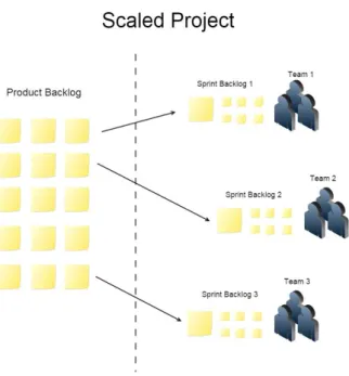
d) Project Scaling
Although Scrum is considered best suitable for projects that don’t require too many team members, Schwaber (2004) lists a group of mechanisms that allow the employment of multiple teams in a project, when necessary. For this author, a project composed by more than one Scrum Team, is referred as a scaled project.When conducting a scaled project, the architecture that will support it must be developed beforehand and it must be complete through Sprints. Simultaneously, functionality must be developed in every Sprint, in order to present to stakeholders afterwards (thus following Scrum rules).
Once a scaled project begins, only one team should sprint as many times as needed in order to build the scaling infrastructure, and its Product Backlog will include extra non-functional requirements to support multi-team development. The process of prioritizing these requirements is called staging, it should take one day only and it occurs before the team’s first sprint (Schwaber, 2004). Figure 2.2 illustrates a scaled project using Scrum.
Figure 2.2 – Scaled Project Illustration
meeting every member represents one team, every attendant must answer the following questions (Rubin, 2012):
What has my team done since we last met that could affect other teams?
What will my team do before we meet again that could affect other teams?
What problems is my team having that it could use help from other teams to resolve?
Scaling practices collide with some Agile principles, such as:
P4. “Business people and developers must work together daily through the project.”
P7. “The most efficient and effective method of conveying information to and within a development team is face-to-face conversation.”
P13. “The best architectures, requirements, and designs emerge from self-organizing teams.”
However, a project that requires more than one team is, usually, rather complex, thus in order to prevent chaos some hierarchy should be installed.
2.1.2 Extreme Programming
Extreme Programming, or XP, was developed by Kent Beck in 1999 and it can be described as a set of best-practices for software development (Abrahamsson, Warsta, Siponen, & Ronkainen, 2003). According to Beck (1999), XP stands on four values:
XPV1 – Communication:One of XP’s main objectives is to keep the right communications
flowing;
XPV2 – Simplicity: By using XP, the team must always think if a certain solution is the
simplest to solve a problem;
XPV3 – Feedback: Having concrete feedback allows the team to increase its understanding of
the project and to improve its confidence;
XPV4 – Courage: The author defines courage mostly as not having fear to take decisions,
especially when it’s necessary to throw away previous work.
a) Practices
Although XP specifies both project lifecycle and project roles, it is mostly acknowledged for its list of practices which have been known to work in software development (Beck, 1999).
XPPr1 – The Planning Game
The Planning Game consists of determining the next release’s scope by combining both business priorities and technical estimates. Business people within the project are responsible for: deciding the project’s scope, prioritizing functionalities, specifying releases’ composition (i.e. how little needs to be done), and determining the dates in which functionalities should be released. On the other hand, technical people are responsible for: estimating how long each feature takes to implement, explaining the consequences of using a certain technique or technology, defining the project’s process (i.e. how the work and the team will be organized), and for detailing the schedule for each release.
XPPr2 – Small Releases
Beck (1999), argues that every release should be as small as possible, it should contain the most valuable business requirements, and it should make sense as a whole.
XPPr3 – Metaphor
A Metaphor is a description of what will be developed during the project. This description must be a story-like explanation which can be understood by every stakeholder involved in the project.
XPPr4 – Simple Design
Every design within a XP project must be as simple as it can be. No duplicated logic should be found in order to avoid any redundancies, and in case of detection, extra code must be deleted immediately.
XPPr5 – Testing
XPPr6 – Refactoring
Refactoring consists of restructuring existing code by turning it simpler or by deleting duplication, without changing the code’s behaviour.
XPPr7 – Pair Programming
In XP projects two people write code using one computer. While one is writing the other is constantly thinking if the chosen approach is going to work and if the system can somehow be simplified. During development pairs don’t stand static; they can actually change during a workday.
XPPr8 – Collective Ownership
Everybody has access to every part of the system, which allows anybody to improve existing code when possible. This practice turns everyone responsible for the whole system.
XPPr9 – Continuous Integration
Code should be integrated into the system as soon as it is ready. The whole system must be tested in order to accept any changes.
XPPr10 – 40 Hour Week
A team must work a maximum of 40 hours per week. Overtime is allowed but it cannot happen two weeks in a row. If overtime is required for two weeks in a row it must be viewed as a problem to be solved.
XPPr11 – On-Site Costumer
The project’s costumer has to be present and available for the team. The costumer should be someone who will actually use the system in the future.
XPPr12 – Coding Standards
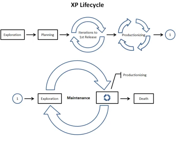
b) Project Lifecycle
A typical XP project can be divided into 6 distinct phases (Beck, 1999): Exploration, Planning, Iterations to First Release, Productionizing, Maintenance, and Death. Figure 2.3 illustrates the lifecycle of a XP project.
Figure 2.3 – XP Lifecycle
XPLc1 – Exploration
During the exploration phase costumers write story cards and programmers try to become familiarized with the technology, the tools and the practices they’ll be using during development. The exploration phase is over when the costumer is satisfied with the number of user stories for a first release and the programmers feel confident about their understanding of the technology, the tools and the practices that will be used during the project.
XPLc1 – Planning
XPLc2 – Iterations to First Release
The schedule for the first release must be broken into one to four-week iterations, where each will produce a set of functional test cases linked to a story card. The first iteration must put the architecture in place and the subsequent ones must be prioritized by their value for the costumer.
XPLc3 – Productionizing
Productionizing marks the end of a release, where the team certifies that the software is ready for production. Thus extra checking and testing take place during this phase. During this phase the feedback cycle must be tightened, i.e. instead of having three-week iterations, for example, the team can start doing one week iterations.
XPLc4 – Maintenance
This phase consists of evolving the system while keeping it running. This phase consists of multiple iteration cycles which start with an exploration phase. The team can review story cards that weren’t implemented in the last iteration and costumers can also write new story cards.
XPLc5 – Death
Once the costumer is satisfied with the system and cannot write any new story cards, development comes to an end. This final phase consists of documenting a tour of the system.
The project can also come to an end if the system is not delivering, the customer needs features which cannot be implemented economically or if the defect rate rises to an excessive level.
c) Roles and Responsibilities
XP also has its own list of roles and responsibilities for a project team. They are (Beck, 1999): Programmer, Customer, Tester, Tracker, Coach, Consultant and “Big Boss”.
XPRR1 – Programmer
XPRR2 – Customer
The costumer is responsible for writing and prioritizing user stories, writing functional tests testers. Since costumers “know what to program” it’s best if they’re the ones that will be using the system afterwards.
XPRR3 – Tester
The tester is responsible for helping the costumer write functional tests, running all tests regularly, for broadcasting test results, and making sure that the testing tools run well.
XPRR4 – Tracker
Tracker gives feedback on the project’s process. He traces the accuracy of previous estimates while giving feedback on how to improve them. The tracker also evaluates if the iteration’s goal is reachable with the existing resources and if any changes must be made in the process.
XPRR5 – Coach
It is the coach’s responsibility to ensure that the team understands and follows the XP process. Since he is responsible for the process as a whole, he is also responsible for understanding XP more deeply than his team.
XPRR6 – Consultant
Sometimes the team gets stuck and needs deep technical knowledge. The consultant is an external member with a great technical expertise that can help the team when necessary.
XPRR7 – Big Boss
The Big Boss is the project’s manager. He’s responsible for making important decisions and for keeping a constant communication with the team in order to determine the project’s state, and to find any problems with the process.
2.1.3 Feature Driven Development
FDD is branded as a method that: is highly iterative, emphasises quality at each step, delivers frequent tangible results, and that provides accurate progress and status information with minimum disruption (Palmer & Felsing, 2002).
This next subchapter is divided into 3 topics – roles practices, and process – since Palmer & Felsing (2002) explain FDD using these distinct elements.
a) Roles
Palmer & Felsing (2002) separate project roles into 3 dimensions: key roles, supporting roles, and additional roles – synthesized below:
Key project roles include:
The Project Manager who’s responsible for reporting progress, controlling budgets, and managing resources;
The Chief Architect who’s responsible for the system’s overall design;
The Development Manager who’s responsible for leading the day-to-day development activities;
The Chief Programmers who are experienced programmers that follow the entire development lifecycle providing guidance to Class Owners;
The Class Owners who are responsible for designing, coding, testing and documenting the system’s features;
The Domain Experts who detain business knowledge to explain to developers the requirements that each feature should fulfil.
Supporting roles include:
The Domain Manager who leads Domain Experts and is responsible for resolving differences in opinions about requirements;
The Release Manager who ensures that chief programmers report progress;
The Language Lawyer who detains a deep knowledge within a certain technology;
The Build Engineer who’s responsible for maintaining and running the regular build process
The Toolsmith who creates small tools to assist the development team;
Additional roles include:
Testers who are responsible for verifying that the system’s functions meet the user’s requirements;
Deployers who convert existing data to new required formats;
Technical Writers who write and prepare documentation.
It’s also important to emphasize that these roles can be played by different team members, which usually occurs in smaller projects.
b) Practices
FDD uses the following software best practices (Palmer & Felsing, 2002): Domain Object Modelling, Developing by Feature, Individual Class (Code) Ownership, Feature Teams, Inspections, Regular Builds, Configuration Management, and Progress Reporting.
FDDPr1 – Domain Object Modelling
Domain Object Modelling consists of building a class diagram which lists the most important objects and shows their relationships within a problem domain. This diagram is used to model the overall system which diminishes incorrect assumptions and inconsistencies during the development process (Palmer & Felsing, 2002).
FDDPr2 – Developing by Feature
FDD emphasizes developing by feature, this means that a set of features must be made and from this list the most valuable features (for the client) must be prioritized. It’s important to highlight that features must be specified in terms of functional requirements, easing the communication between the client and the development team. FDD supports that each feature (which corresponds to a single iteration) should be implemented within two weeks (Palmer & Felsing, 2002).
FDDPr3 – Class (Code) Ownership
FDDPr4 – Feature Teams
Similarly to class ownership, features are also assigned to different teams. Each team will have an experienced professional as leader who coordinates the efforts of multiple developers. Palmer & Felsing (2002), suggest that each team should have three to six people and all the Class Owners who are responsible for each class within one feature should be in the same team.
FDDPr5 – Inspections
Inspections consist of code review and testing. The primary purpose of inspections is detecting defects, although there are two other benefits that arise from this activity: knowledge transfer and standards conformance. Having developers running through code together allows them to explain and learn better coding practices. Additionally, once developers know that their code will be inspected, they are more likely to develop according to the agreed coding standards (Palmer & Felsing, 2002).
FDDPr6 – Regular Builds
Having Regular Builds consists on integrating, continuously, the developed code with the rest, building the complete system. A regular build schedule helps to highlight integration errors early and ensures the existence of an up-to-date system that can be demonstrated to the client (Palmer & Felsing, 2002).
FDDPr7 – Configuration Management
Configuration Management consists of tracking the changes made on the current work. FDD suggests tracking changes both in code and in documentation, such as requirements, contracts, test results and other artefacts (Palmer & Felsing, 2002).
FDDPr8 – Progress Reporting
c) FDD Lifecycle
FDD consists of five sequential processes in which the system is designed and built (Palmer & Felsing, 2002): Develop an Overall Model, Build a Features List, Plan by Feature, Design by Feature, and Build by Feature. Figure 2.4 illustrates the FDD process.
Figure 2.4 – FDD Process (Source: Palmer & Felsing, 2002: p. 57)
FDDLc1 – Develop an Overall Model
At this stage the team should be aware of the project’s scope and have a list of basic requirements. During this activity, Domain Experts perform detailed walkthroughs for each area of domain that is to be modelled. Once this is completed, small groups are formed from the domain and the development areas (specially the Domain Experts and Chief Programmers) to compose a model. The groups then discuss their ideas with their proposed models to obtain the Overall Model (Palmer & Felsing, 2002).
FDDLc2 – Build a Features List
During this activity Chief Programmers use the previous deliverable, the Overall Model, and other documents such as requirements lists, to build a Features List. This list consists of a functional decomposition of the Overall Model into areas, which comprise activities, which then comprise features. Palmer & Felsing (2002) describe features as granular functions eXPPressed in client-valued terms (Palmer & Felsing, 2002).
FDDLc3 – Plan by Feature
FDDLc4 – Design by Feature
During this activity, Chief Programmers schedule the development for the next feature, or group of features, and then form feature teams by identifying the owners of the classes that comprise the selected features. Once the development teams are formed they develop a detailed sequence diagram for each feature being designed and then the Chief Programmer refines the object model accordingly. This activity is repeated for each feature (Palmer & Felsing, 2002).
FDDLc5 – Build by Feature
During this activity Class Owners implement the required items for their classes to support each feature and the developed code is tested and inspected in the order determined by the Chief Programmer. This activity is repeated for each feature (Palmer & Felsing, 2002).
2.1.4 Rational Unified Process
The Rational Unified Process (RUP) was developed and marketed by Rational Software – a software company acquired by IBM. Despite being considered an agile method, since it “embraces change” and its process relies on iterative development, RUP contradicts agile principles by adopting “heavy documentation” during the project’s lifecycle (Borth & Shishido, 2013). In order to describe RUP, it’s important to comprehend that it was built on the following software best practices (Kruchten, 2000):
Develop Software Iteratively: Allows an early understanding on the project’s lifecycle, encourages user feedback, enables an objective assessment of the project’s status, spreads workload throughout the project’s lifecycle, and gives stakeholders a concrete evidence of the project’s status.
Manage Requirements: Understanding which requirements add the most value to the company; eliciting, organizing, and documenting the system’s required constraints; evaluating and assessing the impact on requirement change; and tracking and documenting trade-offs and decisions
Use Component-based Architectures: A broad description for the system’s architecture that allows its understanding form multiple perspectives
Continuously Verify Software Quality: Since problems are harder to fix after deployment, it’s crucial to continuously asses the system’s quality in terms of functionality, reliability and performance.
Control Changes to Software: It is important to coordinate developers’ activity in order to monitor changes and also to find and react to problems.
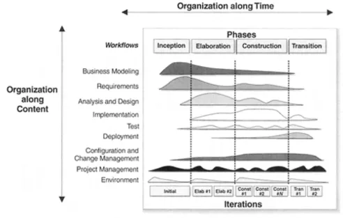
The RUP is characterized in two structures: the Static Structure and the Dynamic Structure. The Static Structure illustrates how workers and activities interact through workflows (organization along content); whereas the Dynamic Structure represents the project’s lifecycle in terms of phases, iterations and milestones (organization along time). Figure 2. shows the allocation of the different workflows within the different project phases.
Figure 2.1. – RUP: Static and Dynamic Structures (Source: Kruchten, 2000: p. 22)
The identified workflows include the following activities:
Business Modelling: To model business use-cases and use-case realizations (i.e. model the business’ processes for external entities and for the company’s internal participants);
Analysis and Design: To specify requirements into an unambiguous design model;
Implementation: To define the organization of the code to be developed, implement and test components as units, and to integrate into an executable system;
Test: To verify the component’s interaction, the component’s integration, and the requirements’ fulfilment, and to ensure all discovered defects are addressed;
Deployment: To test the software in its final operational environment, to package, distribute, and installing the final product, and to train end users and the sales force;
Configuration and Change Management: To maintain the integrity of the project’s artifacts;
Project Management: People Management (hiring, training, coaching), Budget Management, Contract Management, Risk Management, and Project Progress Monitoring activities;
Environment: To provide support in terms of tools, processes, and methods (thus removing human-intensive and error-prone activities).
Each workflow (Static Structure) is documented graphically, which eases the process’ interpretation, demonstrating workers’ responsibilities towards activities and artefact creation/management.
Regarding the Dynamic Structure, Kruchten (2000) identifies 4 different phases in a project’s lifecycle: Inception, Elaboration, Construction, and Transition. The end of each process represents a project milestone.
During the project’s Inception the team specifies the project’s vision, business case, and its scope. This phase is concluded with the Lifecycle Objective Milestone. On the other hand, the Elaboration phase is characterized by planning the necessary activities and resources, specifying features and requirements, and designing the system’s architecture. The Elaboration phase is concluded with the Lifecycle Architecture Milestone.
Unlike other Agile Methods, RUP lists artefacts related to Project Management such as Product Acceptance Plan, Risk Management Plan, Measurement Plan, etc. RUP does not demand the use of all its artefacts, the method itself is adaptable to different projects, but it gives few guidelines in what artefacts to implement, thus relying on the project manager’s knowledge and experience.
RUP defines 30 different roles within a project, including: stakeholders, technical and administrative roles, and also reviewers and analysts for both technical and administrative tasks.
From this method emerged the Agile Unified Process (AUP) – a cut-down, simplified version of the RUP2.
2.1.5 Dynamic Systems Development Method
According to its consortium website3, the Dynamic Systems Development Method (DSDM) was first
described in 1994, emerging from a method named Rapid Application Development (RAD) from both the IT and non-IT context. This particular method was developed with efforts from different authors, since its consortium operates on a collegiate model. Its website provides open-access to the method’s manual, the DSDM Atern Handbook. This method description is based on the ebook present on the consortium’s website (DSDM Consortium, 2008).
DSDM’s main concept is to have the product’s functionality as a variable, instead of the project’s schedule, cost or quality. Thus, countering traditional approaches where resources are added, the delivery date is extended, or quality becomes compromised if the project goes off track.
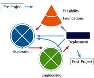
a) Process
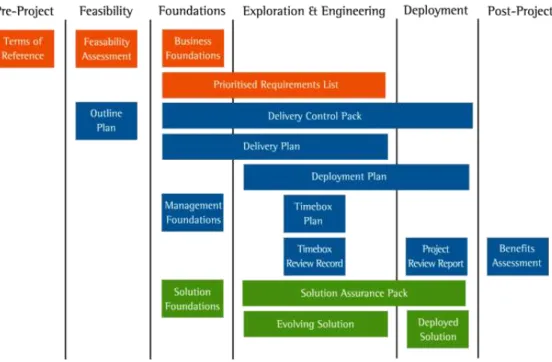
DSDM’s lifecycle has seven distinct phases (Figure 2.): Pre-Project, Feasibility, Foundations, Exploration, Engineering, Deployment, and Post-Project.
Figure 2.2. – DSDM Lifecycle (Source: http://www.dsdm.org/content/6-lifecycle)
Pre-Project
The Pre-Project phase consists of formalising the project’s proposal, placing its context on the organization’s current activity. Its objectives are: to describe what business problem will be addressed with the final result, to identify who will be the project’s Business Sponsor and Business Visionary, to access the project’s harmony with business strategy, and also to scope, plan, and resource the Feasibility phase.
Feasibility
This phase provides the first opportunity to study the project’s viability in terms of both business and technical perspectives. Despite having this phase in the project’s inception, its viability should be continually assessed throughout its lifecycle. This stage’s objectives are: to determine if there is a feasible solution to the business problem described during Pre-Project, to identify the benefits to arise with the end result, to outline possible approaches for delivery and for project management, to describe organisation aspects, to state rough estimates of timescale and costs, and to plan the Foundations phase.
Foundations
Exploration
The Exploration phase is used to iteratively investigate detailed business requirements and translate them into a viable solution, detailing the high-level requirements which were established in the previous phase. This phase’s objective is to create a functional solution that demonstrably meets the needs of the business and to provide an early view of the final product to the wider organisation.
Engineering
The Engineering phase is used to evolve the preliminary solution created during the Exploration phase. This can be characterized as a continuous development of the final product in terms of performance, capacity, security, supportability, and maintainability. This phase can work iteratively with the Exploration phase.
Deployment
This phase’s primary purpose is to implement the project’s solution. Therefore, distributing or selling it outside of the organisation or, in some cases, inside the organisation if the project’s main client is in fact within the organisation. As secondary objectives, the Deployment phase is used as a review point for future development and to formally bring the project to a close. There are 4 possible outcomes from this phase:
All requirements have been fulfilled – project goes to the Post-Project phase;
A major change of scope was discovered – project goes back to the Foundations phase;
Features that were already planned are now added – project goes back to the Exploration phase;
The next increment will solely address technical aspects – project goes back to the Engineering phase.
Post-Project
The Post-Project phase, which occurs once the final product’s value can be measured (three to six months prior to the project’s completion), acts as an assessment in order to prove if whether the benefits described during the project were achieved.
b) Artefacts
depending on their purpose. DSDM, like RUP, also points out that not all the deliverables are mandatory for every project, their use will usually depend on contractual relationships and corporate standards.
Figure 2.3. – DSDM Artefacts (Source: http://www.dsdm.org/content/8-products)
During Pre-Project only one brief deliverable is presented, named Terms of Reference. This can be a short document, a simple email or even a verbal agreement which will be sufficient to allow a potential project to enter the next phase. This artefact contains a brief outline of the business’ needs, the project’s objectives, and the project’s scope to address those needs.
The Feasibility phase is composed by the delivery of two distinct documents: The Feasibility Assessment and the Outline Plan. The first provides a high-level overview of the project, while assessing its feasibility from a business and technical perspective, and addressing risk by presenting a description and a mitigation strategy for any risks significant enough to influence the project’s viability. On the other hand, the Outline Plan provides an overview of the project from a management and solution delivery perspective, while describing the resources required for the project, the organisational structure and processes needed, an outline schedule for the project overall, and a detailed plan for the Foundations phase.
The Business Foundations provides relevant information about transformation of the organisation’s processes and how the project will contribute to the required change. The Management Foundations describes governance and organisational aspects of the project, demonstrating how the project will be managed. Thus, providing a validation of the project’s objectives and Success Criteria, the project’s organisation (including roles and responsibilities), a description of the project’s monitoring tools, and an overview of the key deliverables. The Solution Foundations is used to define the development approach, the system’s architecture, and to demonstrate a solution prototype.
The Prioritised Requirements List, as its name suggests, describes the requirements which the project needs to address in order to meet its objectives. The prioritisation is done according to the MoSCoW method4. The Delivery Plan refines and elaborates the schedule described in the Outline Plan. Both
documents are used during the Exploration and the Engineering phases.
Finally, the Delivery Control Pack comprises reports, documents and logs related to the project’s status. This can include the use of an issues log, a communications log, a burn-down chart, and/or a project dashboard. This artefact, or set of artefacts, has relevance in the project until its Deployment phase.
The Exploration and Engineering phases include the elaboration of five products: the Timebox Plan, the Timebox Review Record, the Deployment Plan, the Evolving Solution, and the Solution Assurance Pack.
The Timebox Plan simply elaborates the schedules on the Delivery Plan, while the Timebox Review Record is basically a trace on the project’s formal acceptance of the completed deliverables.
The Deployment Plan is a detailed plan for the Deployment phase, which includes a description of the work to be completed, the dates associated with the key activities and milestones, the allocation of resources, and an identification of contingency plans.
The Evolving Solution which is used to demonstrate the current understanding of the requirements is composed by five parts: the Business Model which demonstrates the solution’s functionality, the Design Model which illustrates how architectural areas should be developed, Prototype Solutions which allow the team to address technical alternatives, the Business User Documentations which is required to help support the effective operation of the solution, and the Support Documentation which provides technical guidance that is required to support live operation of the solution.
The Solution Assurance Pack is composed by three parts: the Solution Review Records which provide a record of all review activity for deliverable components, the Business Testing Pack that demonstrates the assessment of the solution in terms of business requirements, and the Technical Testing Pack which demonstrates the assessment of the solution in terms of technical requirements.
The Deployment phase includes the development of two products: the Deployed Solution (which is basically the end result for the current increment), and the Project Review Report that includes what has been accomplished in the last increment and that links it to the Business Case that justified it.
Finally, the Post-Project phase includes only one deliverable, the Benefits Assessment, which describes how the solution’s benefits have actually accrued.
c) Roles and Responsibilities
Like most of Agile methods DSDM also provides a list of roles and responsibilities within a project team. These roles can be divided into three categories: Project-level roles, Solution Development, and Other roles.
Within the Project-level roles are managers and co-ordinators of the project, including the Business Sponsor who provides the overall strategic direction and funding, the Business Visionary who’s responsible for interpreting the business’ needs (as referred by the Business Sponsor), the Project Manager who ensures that the project’s resources are used effectively to create the final solution, and the Technical Co-ordinator who is responsible for ensuring that the project is technically coherent and meets the desired technical quality standards.
Within the Solutions Development sector there are six different roles: the Team Leader, the Business Ambassador, the Business Advisor, the Solution Developer, the Business Analyst, and the Solution Tester.
The Team Leader, who reports to the Project Manager, ensures that a Solution Development Team functions as a whole and meets its objectives, co-ordinating product delivery aspects at a detailed level.
solution or by someone who can simply provide legal or regulatory advice. The Business Analyst facilitates the communication between business and technical participants by ensuring it is done unambiguously and timely.
The Solution Developer, who is responsible for translating the business requirements and turning them into a deployable solution, is also responsible for producing unit tests. Alternatively, the Solution Testers are responsible for testing the solution as a whole.
The two other roles in the DSDM are the Workshop Facilitator who’s a moderator during project meetings and the Atern Coach who’s responsible for ensuring that the DSDM is being employed correctly.
2.1.6 Other Methods
a) Internet-Speed Development (ISD)
Internet-Speed Development (ISD) provides a framework in order to handle fast releases, which are necessary to cope with the fast-paced software development environments. This method draws from the Synch-and-Stabilize approach by Microsoft (Abrahamsson et al., 2003).
The method Synch-and-Stabilize consists on separating the project in three or four subprojects, where features are developed according to priority. During each development cycle developers work in parallel with constant builds, tests and bug-fixes (Cusumano & Selby, 1997).
ISD focuses on the following practices (Baskerville, Ramesh, Levine, Pries-Heje, & Slaughter, 2003): Parallel Development, Constant Releases, Tools Utilization to speed design and coding, Customer Integration in the development environment, Stable Architecture Establishment, Components Reuse, Ignore Maintenance (new versions are developed from scratch and products are not documented due to their short life-span), and Tailoring the method daily.
b) Adaptive Software Development (ASD)
According to its author, James A. Highsmith (2000), Adaptive Software Development (ASD) provides a framework of concepts, practices, and guidelines instead of a set of rules and tasks. Therefore, this particular method encompasses how projects should be approached from a cultural and organisational perspective.
The ASD approach has six key characteristics (J. Highsmith, 2002):
Mission focused: Development should be made with project mission in mind at all times. Nevertheless, the project’s mission may evolve during the project’s lifecycle;
Feature based: Development must be oriented by the system’s functionalities not by task driven guidelines. In addition, this allows development to be broken down into smaller pieces;
Iterative: Development is carried through cycles;
Time-boxed: Time-boxing has the purpose to force hard trade-off decisions, instead of forcing actual deadlines;
Risk driven: Requirements must be prioritised according to risk;
Change tolerant: This characteristic is implicit within every agile method. Change must be embraced right from the project’s inception.
ASD recognizes 3 different phases within a development cycle (J. Highsmith, 2000): Speculate, Collaborate, and Learn.
The first phase refers to a planning stage; the author chooses to call it Speculate in order to acknowledge the uncertainty around software development projects. While the second phase is called Collaborate in order to describe the need of cooperation during development. Finally, the last stage consists of reviewing the project’s process and progress, while evaluating the possibility of changing requirements. A cycle should last between four and eight weeks.
c) Lean Development (LD)
Highsmith (2002), states that Lean Development (LD) is a software management tool, originated by Bob Charette, which emerged from the lean manufacturing philosophy. Its practices and techniques do not differ significantly from other methods, but its main characteristic it’s the linkage with the philosophies that rose from the Toyota Production System (TPS).
LD’s principles are (J. Highsmith, 2002):
LDP1. Satisfying the customer is the highest priority; LDP2. Always provide the best value for the money; LDP3. Success depends on active customer participation; LDP4. Every LD project is a team effort;
LDP5. Everything is changeable;
LDP6. Domain, not point, solutions – use solutions that can be used across multiple domains; LDP7. Complete, don't construct – acquiring available solutions should be considered first; LDP8. An 80 percent solution today instead of 100 percent solution tomorrow;
LDP9. Minimalism is essential;
LDP10. Needs determine technology – objectives must be considered before the technology; LDP11. Product growth is feature growth, not size growth – business features dictate progress; LDP12. Never push LD beyond its limits –the method’s boundaries must be understood.
d) Crystal
The author names the methods with a colour code, from clear to red, being the clear a lighter method, thus less bureaucratic, and red a heavier method with the use of more documentation and rules (Cockburn, 2002).
The project’s criticality does not show any impact on tailoring an agile approach, it is used has a criterion for adopting agile –an agile approach shouldn’t be adopted for life-critical systems according to Crystal. In addition, Crystal does not provide concrete guidance on how to apply the different methods.
e) Kanban
Kanban, in software development, is based on the technique within lean production and it is mainly used for limiting Work-in-Progress and visualizing workflow. This technique consists of using a board divided into columns, each representing a software development phase (e.g. Specification, Development, Review, and Testing), and placing labels corresponding to tasks on the board accordingly (Anderson, 2010). This technique is further detailed in a) Product Backlog (SA1), Sprint Backlogs (SA2) & Kanban.
2.2
Agile Methods Discussion and Comparison
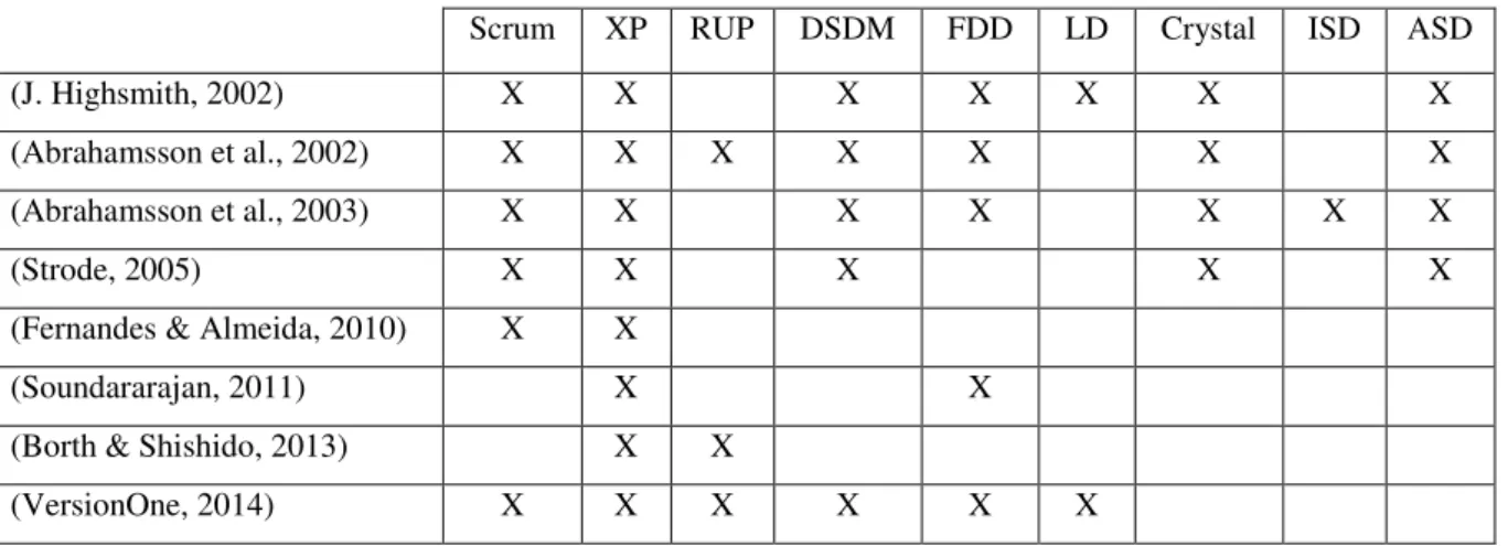
The review, analysis, and comparison of agile methods it’s not a recent topic since most agile methods appearances date back to the nineties and the manifesto for agile software development was signed in 2001. Table 2.1 shows previous works on comparisons and the methods that were considered in each study.
Table 2.1 -– Previous works on Agile methods’ comparison
Scrum XP RUP DSDM FDD LD Crystal ISD ASD
(J. Highsmith, 2002) X X X X X X X
(Abrahamsson et al., 2002) X X X X X X X
(Abrahamsson et al., 2003) X X X X X X X
(Strode, 2005) X X X X X
(Fernandes & Almeida, 2010) X X
(Soundararajan, 2011) X X
(Borth & Shishido, 2013) X X