José Francisco Rodrigues Malta
Licenciado em Ciências da Engenharia Química e Bioquímica
Joule-Heating Effect for Erasing Information in
PDLCs Devices with Memory
Dissertação para obtenção do Grau de Mestre em Engenharia Química e Bioquímica
Orientador: João Carlos da Silva Barbosa Sotomayor, Professor Auxiliar, FCT-UNL
Presidente: Mário Fernando José Eusébio, Professor Auxiliar, FCT-UNL
Joule-Heating Effect for Erasing Information in PDLCs Devices with Memory
Copyright © José Francisco Rodrigues Malta, Faculdade de Ciências e Tecnologia, Universida-de Nova Universida-de Lisboa.
“Study hard what interests
you the most in the most undisciplined, irreverent and
original manner possible.”
Agradecimentos
Ao Professor João Sotomayor por me ter aceite neste projeto, pela motivação e entusiamo transmitidos, por toda a sua disponibilidade sempre que ao longo do trabalho questões ou pro-blemas surgiram, e por me ter dado a oportunidade de levar algum do trabalho desenvolvido através de um poster ao XII Encontro Nacional de Química-Física.
À Ana Mouquinho (Tri-Mamã), pelo apoio dado no laboratório, pelas conversas, pelos conselhos, pela ajuda no tratamento de gráficos do DSC e principalmente por me ter dado na cabeça sempre que precisei. Ao Diogo Costa por me ter dado “uma mãozinha” sempre que já
não tinha mais mãos e pelos momentos divertidos nas nossas pausas.
À Professora Madalena Dionísio por ter disponibilizado o DSC para os testes neste traba-lho. Ao Professor Jorge Caldeira por toda a ajuda dada na caracterização de superfícies através de AFM e à Daniela Gomes pela caracterização através de SEM. Ao Professor Mário Eusébio pelo desenvolvimento do programa de estudos eletro-óticos e ao Professor João Figueirinhas pela ajuda teórica dada.
Ao senhor Zé Luís pela sua disponibilidade e simpatia sempre que precisei de cortar al-guns vidros. À Dona Idalina e Dona Conceição pela ajuda e amabilidade sempre que precisava de levar alguma coisa dum laboratório para o outro. À Dona Maria José pelas vezes que a cha-teei em pedir fita adesiva quando precisava de montar o sistema de medição de transmitâncias com a temperatura.
Aos meus colegas e amigos, Ana Rita Nabais, João Valentim, André Oliveira e Liliana Beatriz pela descontração nas horas de almoço e pela partilha de desabafos sobre os nossos obs-táculos acompanhada pela cafeína. Ao Tomás Monteiro por ter salvado os computadores do la-boratório sempre que resolviam não funcionar. Ao David Lopes pela companhia e partilha de conhecimentos ao longo deste trabalho.
À minha família em especial à minha irmã por ter aturado as minhas conversas à hora de jantar e aos meus pais que sempre estiveram do meu lado acontecesse o que tivesse que aconte-cer.
Resumo
O principal objetivo deste trabalho é tentar encontrar a melhor maneira de apagar in-formação escrita em dispositivos PDLC com memória por efeito de joule, e como é que pode ser aplicado num sistema de janelas inteligentes. Para isso foi usado uma mistura composta por 70% cristal líquido E7 e 30% oligómero PEGDMA875 em várias células com características diferentes.
Primeiro de tudo, foram feitos estudos DSC para o E7, oligómero e mistura
E7/oligómero para determinar as suas propriedades térmicas. Depois, foram testadas seis tipos de células num estudo eletro-ótico. Verificou-se que o Efeito de Memória Permanente (PME) está apenas presente em células cujos vidros tenham alinhamento planar.
Análises AFM e SEM foram feitas nos vidros com o fim de determinar como o alinha-mento planar consegue influenciar o PME da mistura polímero/cristal líquido e, por conseguin-te, o desempenho do PDLC. Em vidros com rubbing foram vistas algumas estrias onde a
mistu-ra segue a sua direção preferencialmente.
Para estas células, foram realizados estudos da capacitância com a temperatura com diferentes tipos de dielétricos no seu interior: sem dielétrico (vazia), com cristal líquido e com polímero. Mais tarde, o mesmo estudo foi efetuado para as células com PDLC mas desta vez com medição da transmitância ao longo da temperatura. As curvas de capacitância e transmitân-cia conseguem dar informação sobre a temperatura de clarificação (Tc). Esta será a temperatura onde se consegue observar a transição opaco-transparente. Foi também verificado que depois de um estudo EO os valores de capacitância aumentam e quando a informação escrita é apagada estes voltam aos seus valores iniciais.
Depois de conhecida cada Tc, os dispositivos foram aquecidos por efeito de Joule com diferentes tipos de corrente, medindo a variação da capacitância. Este estudo foi feito primeiro para células antes do estudo EO (células sem informação escrita) para encontrar que intensida-des de corrente conseguem chegar à Tc e depois para células depois do estudo EO (células com informação escrita). Apenas um certo grupo de intensidades de corrente consegue apagar com-pletamente a informação escrita. Isto pode ser verificado quando, durante o aquecimento, a Tc é alcançada, e se os valores de capacitância no final do aquecimento são iguais aos valores antes do estudo EO.
Palavras-Chave: PDLC, Cristal Líquido, Efeito de Joule, Efeito de Memória Permanente,
Abstract
The main objective of this work is trying to find the best way to erase written infor-mation in PDLC devices with memory by Joule-heating effect, and how this can be applied on a smart window system. Then, a mixture composed by 70% liquid crystal E7 by Merck and 30% oligomer PEGDMA875 was used in several cells with different properties.
First of all, DSC studies were done for E7, oligomer and mixture E7/oligomer to deter-mine their thermal properties. Then, six different cells with different alignment types were test-ed in an electro-optical (EO) study. It was verifitest-ed that the Permanent Memory Effect (PME) is only present in cells which glasses have planar alignment.
AFM and SEM analysis were done on glasses to determine how the planar alignment can affect the mixture polymer/liquid crystal and thus the PDLC performance. On rubbed glass-es some stretch marks were detected where the mixture follows their preferred direction. For these cells, capacitance studies with temperature were done for three types of dielectrics inside: with no dielectric (empty), with liquid crystal, and with polymer. Afterwards, the same study was also done for cells with PDLC but this time with a transmittance measuring along the tem-perature. The capacitance and transmittance curves can give the information about the clarifica-tion temperature (Tc). This will be the temperature where the opaque-transparent transiclarifica-tion can be observed. It was also verified that after EO study the capacitance values increases and when the written information is erased they return to previous values.
After known each Tc, the devices were heated by Joule-Heating Effect with different levels of current, measuring the capacitance variation. This study was done first for the cells before EO study (with no written information) to find which current intensities can reach the Tc and then for the cells after EO study (with written information). Only a group of current intensi-ties can completely erase the written information. This can be verified when, during heating, the Tc is reached, and if the capacitances values in the end of the heating are equal to values before EO study.
Keywords: PDLC, Liquid Crystal, Joule Heating-Effect, Permanent Memory Effect,
Symbols, Abbreviations and Acronyms
5CB 4-cyano-4'-n-pentyl-biphenyl 7CB 4-cyano -4'-n-heptyl-biphenyl 8OCB 4-cyano-4'-n-oxyoctyl -biphenyl 5CT 4-cyano-4''-n-pentyl-p-terphenyl
A Area
AFM Atomic Force Microscopy AIBN α,α-azobisisobutyronitrile BOO Bond Orientational Order
C Capacitance
C⊥ Capacitance perpendicular to the director
C∥ Capacitance parallel to the director
c Speed of light in vacuum
d Thickness (Distance between plates) DSC Differential Scanning Calorimetry
E Electric Field
E7 Mixture of four nematic liquid crystals by Merk E90 Electric field for 90% of maximum transmittance
FP90 F90 Central Processor H Heat by Joule-Heating Effect
I Current Intensity
ITO Indium Thin Oxide
kd Rate constant for the dissociation of the initiator
ki Rate constant for the initiation step
kp Rate constant for the propagation step
kt Rate constant for the termination step by combination
LC Liquid Crystal
LCR Inductance Capacitance Resistance Bridge
Director vector
ne Extraordinary refractive index
no Ordinary refractive index
np Polymer refractive index
OO Orientational order
PDLC Polymer Dispersed Liquid Crystal PEGDMA875 Poly(ethyleneglycol) dimethacrilate 875 PME Permanent Memory Effect
POM Polarized Optical Microscopy
PO Positional Order
PS Power Supply
Q Electric charge
R Resistance
SEM Scan Electron Microscopy
T Transmittance (%)
Tc Clarification Temperature
TNI Nematic Isotropic Transition Temperature
Tg Glass Transition Temperature
TOFF’ Transmittance after an applied field
TON Transmittance during an applied field (Maximum Transmittance)
V Voltage
Vth Threshold Voltage
v Speed of Light
Δn Optical Anisotropy (Birefringence)
Δ Dielectric Anisotropy
Dielectric Permittivity
⊥ Dielectric constant perpendicular to the director ∥ Dielectric constant parallel to the director p Polymer dielectric constant
Content
AGRADECIMENTOS... VII RESUMO ... IX ABSTRACT ... XI SYMBOLS, ABBREVIATIONS AND ACRONYMS ... XIII
CHAPTER 1 - INTRODUCTION ... 1
1.1. LIQUID CRYSTALS ... 1
1.1.1. Brief History of Liquid Crystals ... 2
1.1.2. Liquid crystals structural units ... 3
1.1.3. Mesophases ... 3
1.1.4. Liquid Crystals Properties ... 6
1.2. POLYMER DISPERSED LIQUID CRYSTALS ... 10
1.2.1. Brief History of PDLC’s ... 11
1.2.2. Permanent Memory Effect ... 11
1.2.3. Factors that can influence PME ... 13
1.2.4. Clarification Temperature on PDLC... 15
1.2.5. Transmittance and Capacitance values in a PDLC with PME ... 17
1.2.6. Applications ... 18
1.2.7 Write, read and erase information on a PDLC device ... 19
CHAPTER 2 - MATERIALS AND METHODS ... 21
2.1.MATERIALS... 21
2.1.1. Liquid Crystal – E7 ... 21
2.1.2. Oligomer and Initiator ... 23
2.1.3 Radical Polymerisation ... 24
2.1.4 PDLC preparation ... 25
2.2.COMMERCIAL AND HANDMADE CELLS ... 26
2.2.1. Alignment on Glass ... 26
2.2.2. Instec commercial cells... 27
2.2.3. Instec Glasses ... 28
2.2.4. Handmade Cells... 28
2.3.EQUIPMENT... 30
2.3.1. Measuring Capacitances - LCR Bridge ... 30
2.3.2. Increasing and Decreasing Temperature - FP90 Central Processor ... 31
2.4.TECHNIQUES ... 33
2.4.1. Capacitance study with Temperature Variation ... 33
2.4.2. Capacitance-Transmittance study with Temperature Variation... 33
2.4.3. Capacitance Study with Joule Heating Effect ... 34
2.4.4. Electro-optical (EO) Study ... 36
2.4.5. Polarized Optical Microscopy (POM) ... 37
2.4.6. Differential Scanning Calorimetry (DSC) ... 38
2.4.7. Atomic Force Microscopy (AFM)... 40
2.4.8. Scanning Electron Microscopy (SEM) ... 41
CHAPTER 3 – RESULTS AND DISCUSSION ... 43
3.1.DSC ANALYSIS ... 43
3.1.1. E7 ... 44
3.1.2. PEGDMA875 + 1%AIBN ... 45
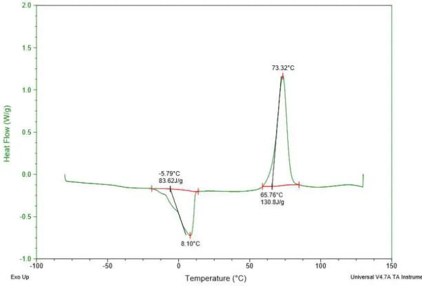
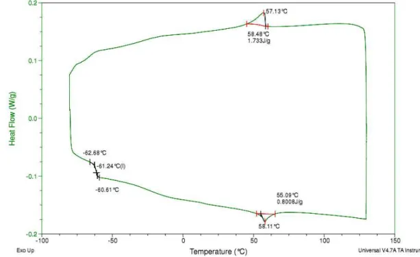
3.1.3. Mixture 70% E7 + 30% PEGDMA875 ... 47
3.1.4. Discussion ... 48
3.2.ELECTRO-OPTICAL (EO)STUDIES ... 49
3.2.1. LC2-20 – Commercial Cell by Instec with planar alignment layer... 49
3.2.2. Handmade cell with parallel rubbing on planar alignment layer (1,5cm2) .... 50
3.2.3. Handmade cell with anti-parallel rubbing on planar alignment layer (1.5cm2) ... 52
3.2.4. Handmade cell with perpendicular rubbing on planar alignment layer (4cm2) ... 53
3.2.5. Handmade cell with Homeotropic Alignment layer (4cm2) ... 55
3.2.6. Handmade cell without alignment layer (4cm2) ... 57
3.2.7. Discussion ... 59
3.3.ATOMIC FORCE MICROSCOPY ON GLASSES... 60
3.3.1 ITO covered glass by Xinyan ... 60
3.3.2 ITO covered glass with planar alignment layer by Instec ... 61
3.3.3 ITO covered glass by Xinyan covered with E7/PEGDMA875 PDLC ... 62
3.3.4 ITO covered glass with planar alignment layer by Instec covered with E7/PEGDMA875 PDLC ... 63
3.3.5. Discussion ... 64
3.4.SCANNING ELECTRON MICROSCOPY ... 65
3.4.1. ITO covered glass by Xinyan ... 65
3.4.2 ITO covered glass with planar alignment layer by Instec ... 66
3.4.3. ITO covered glass covered with E7/PEGDMA875 PDLC... 67
3.4.4 ITO covered glass with planar alignment layer by Instec covered with E7/PEGDMA875 PDLC ... 68
3.5.CAPACITANCE STUDY WITH TEMPERATURE VARIATION ... 70
3.5.1. Empty cells ... 70
3.5.2. Cells with E7 ... 72
3.5.3. Cells with polymerised PEGDMA875 ... 76
3.5.4 Discussion... 79
3.6.1. LC2-20 cell with PDLC ... 80
3.6.2. Parallel rubbing on planar alignment layer cell (1.5cm2) with PDLC ... 82
3.6.3. Anti-parallel rubbing on planar alignment layer cell (1.5cm2) with PDLC ... 83
3.6.4. Perpendicular rubbing on planar alignment layer cell (4cm2) with PDLC.... 85
3.4.5. Discussion ... 86
3.7.CAPACITANCE STUDY WITH TEMPERATURE VARIATION AFTER EO STUDY... 89
3.7.1. LC2-20 cell with PDLC ... 89
3.7.2. Parallel rubbing on planar alignment layer cell (1.5cm2) with PDLC ... 90
3.7.3. Anti-parallel rubbing on planar alignment layer cell (1.5cm2) with PDLC ... 91
3.7.4. Perpendicular rubbing on planar alignment layer (4cm2) with PDLC ... 92
3.7.5 Discussion... 93
3.8.CAPACITANCE STUDY WITH JOULE-HEATING EFFECT ... 94
3.8.1. Parallel rubbing on planar alignment layer cell (1.5cm2) with PDLC ... 94
3.8.2 Anti-parallel rubbing on planar alignment layer cell (1.5cm2) with PDLC .... 97
3.8.3. Perpendicular rubbing on planar alignment layer cell (4cm2) with PDLC..100
3.8.4. Discussion ...103
CHAPTER 4 – CONCLUSIONS ... 105
CHAPTER 5 – BIBLIOGRAPHY ... 107
APPENDIX A – DSC ANALYSIS ... 111
APPENDIX B – AFM IMAGES ... 115
Figures Index
Chapter 1
FIGURE 1.1- THERMOTROPIC LIQUID CRYSTAL TRANSITION3 ... 1
FIGURE 1.2.-EXAMPLE OF A MESOGEN MOLECULE (5CB)8 ... 3
FIGURE 1.3.-NEMATIC PHASE ILLUSTRATION AND RESPECTIVE TEXTURE OBSERVED WITH A POLARIZED OPTICAL MICROSCOPE WITH CROSSED POLARIZERS312 ... 4
FIGURE 1.4-CHOLESTERIC PHASE ILLUSTRATION AND RESPECTIVE TEXTURE OBSERVED WITH A POLARIZED OPTICAL MICROSCOPE WITH CROSSED POLARIZERS3 ... 5
FIGURE 1.5–ILLUSTRATION OF SMECTIC PHASES A– A) AND C B) AND RESPECTIVE TEXTURES OBSERVED WITH A POLARIZED OPTICAL MICROSCOPY WITH CROSSED POLARIZERS3 ... 5
FIGURE 1.6-ILLUSTRATIVE SCHEME OF LIGHT CROSSING A BIREFRINGENT MATERIAL15 ... 6
FIGURE 1.7-BIREFRINGENCE ON NEMATIC LIQUID CRYSTALS16 ... 7
FIGURE 1.8-DIELECTRIC PERMITTIVITY ALONG TEMPERATURE FOR A LIQUID CRYSTAL WITH POSITIVE DIELECTRIC ANISOTROPY 19 ... 8
FIGURE 1.9-ORIENTATION OF LIQUID CRYSTAL MOLECULES WITH A) POSITIVE AND B) NEGATIVE DIELECTRIC ANISOTROPY AS A RESPONSE TO THE APPLIED ELECTRIC fiELD19 ... 9
FIGURE 1.10.-ILLUSTRATION OF A PDLCDEVICE,(A)OFFSTATE,(B)ONSTATE... 10
FIGURE 1.11-TRANSMITTANCE VARIATION WHEN AN ELECTRIC FIELD IS APPLIED (A-NO HYSTERESIS,B-WITH HYSTERESIS,C-WITH PME)24 ... 13
FIGURE 1.12.-ANCHORING EFFECT ON LIQUID CRYSTAL MOLECULES A) WHEN V=0; B) WHEN V=VTH ... 14
FIGURE 1.13-THE TWO DIFFERENT TYPE OF MORPHOLOGIES IN PDLC DEVICES: A)SWISS CHEESE; B)POLYMER BALL24 ... 14
FIGURE 1.14-ILLUSTRATIVE SCHEME OF A CAPACITOR ... 16
FIGURE 1.15-CAPACITANCE VARIATION WHEN AN ELECTRIC FIELD IS APPLIED ON A LC DEVICE28ADAPTED ... 17
FIGURE 1.16-EXAMPLE OF PDLC APPLICATION IN A SMART WINDOW: A)ONSTATE B)OFFSTATE29ADAPTED ... 18
FIGURE 1.17-WRITE, READ AND ERASE INFORMATION ON A SET OF 16PDLC CELLS DEVICE30ADAPTED ... 19
Chapter 2
FIGURE 2.1.–OLIGOMER PEGDMA87533 ... 23FIGURE 2.2–AIBN(Α,Α-AZOBISISOBUTYRONITRILE)34... 23
FIGURE 2.3–STOVE USED FOR POLYMERISATION ... 25
FIGURE 2.4-ILLUSTRATIVE SCHEME OF HOMEOTROPIC AND PLANAR ALIGNMENT36 ... 26
FIGURE 2.5-ILLUSTRATION OF PARALLEL,ANTI-PARALLEL37 AND PERPENDICULAR36 ALIGNMENT ON DEVICES ... 27
FIGURE 2.6-SCHEME OF A COMMERCIAL CELL LC2-20 FROM INSTEC38 ... 27
FIGURE 2.7-ILLUSTRATIVE FIGURE OF A SUBSTRATE GLASS DA256A-PI FROM INSTEC INC. ... 28
FIGURE 2.8-ILLUSTRATIVE SCHEME OF HANDMADE CELLS WITH: A)PARALLEL; B)ANTI-PARALLEL; AND C) PERPENDICULAR RUBBING ... 29
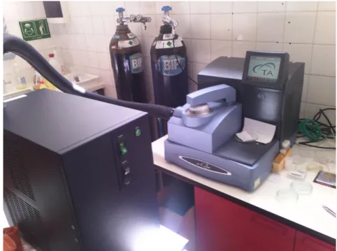
FIGURE 2.10-LCRPROGRAMMABLE BRIDGE HM8118 SYSTEM FROM HAMEG40 ... 30 FIGURE 2.11-SHORT CIRCUIT FOR LCRBRIDGE CALLIBRATION40 ... 31 FIGURE 2.12-F90CENTRAL PROCESSOR METLER TOLEDO41... 31 FIGURE 2.13-EX4210R POWER SUPPLY FROM TTI43 ... 32 FIGURE 2.14-ASSEMBLE USED FOR CAPACITANCE MEASURING WITH TEMPERATURE VARIATION ... 33 FIGURE 2.15-ASSEMBLE FOR CAPACITANCE-TRANSMITTANCE STUDY WITH TEMPERATURE VARIATION ... 34 FIGURE 2.16-ASSEMBLE FOR CAPACITANCE STUDY WITH JOULE HEATING EFFECT ... 34 FIGURE 2.17-SCHEME FOR MEASURING CAPACITANCES WITH JOULE-HEATING EFFECT ... 35 FIGURE 2.18-ACRYLIC SUPPORTERS USED FOR HEATING BY JOULE-EFFECT ... 36 FIGURE 2.19-ELECTRO-OPTICAL SYSTEM ... 36 FIGURE 2.20-CROSSED POLARIZERS AND POLARIZED LIGHT ILLUSTRATION47 ... 37 FIGURE 2.21-POM APPARATUS ... 38 FIGURE 2.22-DSC APPARATUS ... 39 FIGURE 2.23-HEAT FLOW VARIATION WITH TEMPERATURE49 ... 39 FIGURE 2.24-AFM TECHNIQUE50 ... 40 FIGURE 2.25-AFM APPARATUS ... 41 FIGURE 2.26-SEM APPARATUS FROM CENIMAT,FCT-UNL52 ... 42
Chapter 3
FIGURE 3.1–FIRST HEATING STAGE FOR E7 ... 44 FIGURE 3.2-HEATING STAGE FOR OLIGOMER PEGDMA875+1%AIBN ... 45
FIGURE 3.3-FIRST HEATING CYCLE FOR POLYMERISED PEGDMA875 ... 46 FIGURE 3.4-FIRST HEATING CYCLE FOR A MIXTURE OF 70%E7 AND 30% OF POLYMERISED PEGDMA875 ... 47 FIGURE 3.5-EO STUDY FOR A LC-20 CELL ... 49 FIGURE 3.6–POM CROSS POLARIZERS’ IMAGES FROM LC2-20 BEFORE AND AFTER EO STUDY ... 50 FIGURE 3.7–EO STUDY FOR THE HANDMADE CELL WITH PARALLEL RUBBING ON PLANAR ALIGNMENT LAYER... 50 FIGURE 3.8-POM CROSS POLARIZERS’ IMAGES BEFORE AND AFTER EO STUDY FOR PARALLEL RUBBING CELL ON
PLANAR ALIGNMENT LAYER... 51 FIGURE 3.9-EO STUDY FOR THE HANDMADE CELL WITH ANTI-PARALLEL RUBBING ON PLANAR ALIGNMENT LAYER
... 52 FIGURE 3.10-POM CROSS POLARIZERS’ IMAGES FROM ANTI-PARALLEL RUBBING ON PLANAR ALIGNMENT LAYER
CELL BEFORE AND AFTER EO STUDY ... 53
FIGURE 3.12-POM CROSS POLARIZERS’ IMAGES BEFORE AND AFTER EO STUDY FOR A PERPENDICULAR RUBBING ON
PLANAR ALIGNMENT LAYER CELL ... 55
FIGURE 3.13-EO STUDY FOR THE HANDMADE CELL WITH HOMEOTROPIC ALIGNMENT LAYER... 55 FIGURE 3.14-POM CROSS POLARIZERS’ IMAGES FOR HOMEOTROPIC ALIGNMENT LAYER CELL ... 56 FIGURE 3.15-EO STUDY FOR A CELL WITHOUT ALIGNMENT ... 57 FIGURE 3.16-POM CROSS POLARIZERS’ IMAGES FOR CELL WITHOUT ALIGNMENT LAYER ... 58 FIGURE 3.17-ITO COVERED GLASS AFM ANALYSIS HEIGHT IMAGE (2D) ... 60 FIGURE 3.18–ITO COVERED GLASS AFM ANALYSIS PHASE IMAGE (2D) ... 60 FIGURE 3.19- ITO COVERED GLASS AFM ANALYSIS HEIGHT IMAGE (3D) ... 60 FIGURE 3.20–ITO COVERED GLASS AFM ANALYSIS PHASE IMAGE (3D) ... 60 FIGURE 3.21–INSTEC GLASS AFM ANALYSIS HEIGHT IMAGE (2D) ... 61 FIGURE 3.22–INSTEC GLASS AFM ANALYSIS PHASE IMAGE (2D) ... 61 FIGURE 3.23-INSTEC GLASS AFM ANALYSIS HEIGHT IMAGE (3D) ... 61 FIGURE 3.24-INSTEC GLASS AFM ANALYSIS PHASE IMAGE (3D) ... 61 FIGURE 3.25-ITO GLASS COVERED WITH PDLCAFM ANALYSIS HEIGHT IMAGE (2D) ... 62 FIGURE 3.26–ITO GLASS COVERED WITH PDLCAFM ANALYSIS PHASE IMAGE (2D) ... 62 FIGURE 3.27-ITO GLASS COVERED WITH PDLCAFM ANALYSIS HEIGHT IMAGE (3D) ... 63 FIGURE 3.28-ITO GLASS COVERED WITH PDLCAFM ANALYSIS PHASE IMAGE (3D) ... 63 FIGURE 3.29-INSTEC GLASS COVERED WITH PDLC PHASE IMAGE (2D) ... 63 FIGURE 3.30-INSTEC GLASS COVERED WITH PDLC HEIGHT IMAGE (2D) ... 63 FIGURE 3.31-INSTEC GLASS COVERED WITH PDLC HEIGHT IMAGE (3D) ... 64 FIGURE 3.32-INSTEC GLASS COVERED WITH PDLC PHASE IMAGE (3D) ... 64 FIGURE 3.33-SEM ANALYSIS FOR ITO COVERED GLASS ... 65 FIGURE 3.34-SEM ANALYSIS FOR INSTEC GLASS ... 66 FIGURE 3.35-SEM ANALYSIS FOR ITO GLASS COVERED WITH PDLC ... 67 FIGURE 3.36-SEM ANALYSIS FOR INSTEC GLASS COVERED WITH PDLC ... 68 FIGURE 3.37-EMPTY LC2-20 CAPACITANCE STUDY WITH TEMPERATURE ... 70 FIGURE 3.38–EMPTY HANDMADE CELL WITH PARALLEL RUBBING ON PLANAR ALIGNMENT LAYER CAPACITANCE
STUDY ... 71
FIGURE 3.39-EMPTY HANDMADE CELL WITH ANTI-PARALLEL RUBBING ON PLANAR ALIGNMENT LAYER
CAPACITANCE STUDY ... 71
FIGURE 3.40-EMPTY HANDMADE CELL WITH PERPENDICULAR RUBBING ON PLANAR ALIGNMENT LAYER
CAPACITANCE STUDY ... 72
FIGURE 3.41-LC2-20 WITH E7 ... 73 FIGURE 3.42-HANDMADE PARALLEL RUBBING ON PLANAR ALIGNMENT LAYER CELL WITH E7 CAPACITANCE STUDY
WITH TEMPERATURE ... 73 FIGURE 3.43-HANDMADE ANTI-PARALLEL RUBBING ON PLANAR ALIGNMENT LAYER CELL WITH E7 CAPACITANCE
STUDY WITH TEMPERATURE ... 74
FIGURE 3.44-HANDMADE PERPENDICULAR RUBBING ON PLANAR ALIGNMENT LAYER CELL WITH E7 CAPACITANCE
STUDY WITH TEMPERATURE ... 75
FIGURE 3.45-LC2-20 WITH PEGDMA875 CAPACITANCE STUDY WITH TEMPERATURE ... 76 FIGURE 3.46-PARALLEL RUBBING ON PLANAR ALIGNMENT LAYER CELL WITH PEGDMA875 CAPACITANCE STUDY
FIGURE 3.47-HANDMADE ANTI-PARALLEL RUBBING ON PLANAR ALIGNMENT LAYER CELL WITH PEGDMA875
CAPACITANCE STUDY WITH TEMPERATURE ... 77
FIGURE 3.48-HANDMADE PERPENDICULAR RUBBING ON PLANAR ALIGNMENT LAYER CELL WITH PEGDMA875
CAPACITANCE STUDY WITH TEMPERATURE ... 78 FIGURE 3.49-CAPACITANCE-TRANSMITTANCE STUDY ALONG TEMPERATURE FOR LC2-20 CELL WITH PDLC–RATE 5ºC/MIN ... 80 FIGURE 3.50CAPACITANCE-TRANSMITTANCE STUDY ALONG TEMPERATURE FOR LC2-20 CELL WITH PDLC–RATE 2ºC/MIN ... 81 FIGURE 3.51-CAPACITANCE-TRANSMITTANCE STUDY ALONG TEMPERATURE FOR PARALLEL RUBBING ON PLANAR
ALIGNMENT LAYER CELL WITH PDLC–RATE 5ºC/MIN ... 82 FIGURE 3.52-CAPACITANCE-TRANSMITTANCE STUDY ALONG TEMPERATURE FOR PARALLEL RUBBING ON PLANAR
ALIGNMENT LAYER CELL WITH PDLC–RATE 2ºC/MIN ... 82 FIGURE 3.53-CAPACITANCE-TRANSMITTANCE STUDY ALONG TEMPERATURE FOR ANTI-PARALLEL RUBBING ON
PLANAR ALIGNMENT LAYER CELL WITH PDLC–RATE 5ºC/MIN ... 83 FIGURE 3.54CAPACITANCE-TRANSMITTANCE STUDY ALONG TEMPERATURE FOR ANTI-PARALLEL RUBBING ON
PLANAR ALIGNMENT LAYER CELL WITH PDLC–RATE 2ºC/MIN ... 84 FIGURE 3.55-CAPACITANCE-TRANSMITTANCE STUDY ALONG TEMPERATURE FOR PERPENDICULAR RUBBING ON
PLANAR ALIGNMENT LAYER CELL WITH PDLC–RATE 5ºC/MIN ... 85 FIGURE 3.56-CAPACITANCE-TRANSMITTANCE STUDY ALONG TEMPERATURE FOR PERPENDICULAR RUBBING ON
PLANAR ALIGNMENT LAYER CELL WITH PDLC–RATE 2ºC/MIN ... 85 FIGURE 3.57-LC2-20 CELL WITH PDLC CAPACITANCE STUDY WITH TEMPERATURE AFTER EO STUDY,2ºC/MIN
RATE ... 89 FIGURE 3.58-PARALLEL RUBBING ON PLANAR ALIGNMENT LAYER CELL WITH PDLC CAPACITANCE VARIATION
WITH TEMPERATURE AFTER EO STUDY,2ºC/MIN RATE ... 90
FIGURE 3.59–ANTI-PARALLEL RUBBING ON PLANAR ALIGNMENT LAYER CELL CAPACITANCE VARIATION WITH
TEMPERATURE AFTER EO STUDY,RATE 2ºC/MIN... 91 FIGURE 3.60-PERPENDICULAR RUBBING ON PLANAR ALIGNMENT LAYER CELL CAPACITANCE VARIATION WITH
TEMPERATURE AFTER EO STUDY,RATE 2ºC/MIN... 92 FIGURE 3.61–JOULE-HEATING EFFECT FOR PARALLEL RUBBING ON PLANAR ALIGNMENT LAYER CELL BEFORE EO
STUDY ... 94
FIGURE 3.62-JOULE-HEATING EFFECT FOR PARALLEL RUBBING ON PLANAR ALIGNMENT LAYER CELL AFTER EO
STUDY ... 96
FIGURE 3.63-JOULE-HEATING EFFECT FOR ANTI-PARALLEL RUBBING ON PLANAR ALIGNMENT LAYER CELL BEFORE EO STUDY ... 97 FIGURE 3.64-ANTI-PARALLEL RUBBING ON PLANAR ALIGNMENT LAYER CELL -JOULE-HEATING EFFECT AFTER EO
STUDY ... 99 FIGURE 3.65-PERPENDICULAR RUBBING ON PLANAR ALIGNMENT LAYER CELL WITH PDLC-JOULE-HEATING
EFFECT BEFORE EO STUDY ... 100
FIGURE 3.66-PERPENDICULAR RUBBING ON PLANAR ALIGNMENT LAYER CELL WITH PDLC-JOULE-HEATING
Appendix A
FIGURE A. 1 - SECOND HEATING STAGE FOR E7………111 FIGURE A. 2 - THIRD HEATING STAGE FOR E7 (ONLY HEATING)………..112 FIGURE A. 3 - SECOND HEATING STAGE FOR PEGDMA875 POLYMERISED……….112 FIGURE A. 4 - SECOND HEATING STAGE FOR THE MIXTURE 30% E7 70% PEGDMA875…………113
Appendix B
FIGURE B. 1 - ITO COVERED GLASS AFM ANALYSIS HEIGHT IMAGE (2D)………115 FIGURE B. 2 - ITO COVERED GLASS AFM ANALYSIS PHASE IMAGE (2D)………..115 FIGURE B. 3 - ITO COVERED GLASS AFM ANALYSIS HEIGHT IMAGE (3D) ………..116 FIGURE B. 4 - ITO COVERED GLASS AFM ANALYSIS PHASE IMAGE (3D) ………..116 FIGURE B. 5 - INSTEC GLASS AFM ANALYSIS HEIGHT IMAGE (2D) ………..116 FIGURE B. 6 - INSTEC GLASS AFM ANALYSIS PHASE IMAGE (2D) ………..116 FIGURE B. 7 - –INSTEC GLASS AFM ANALYSIS HEIGHT IMAGE (3D) ………..117 FIGURE B. 8 - INSTEC GLASS AFM ANALYSIS HEIGHT IMAGE (2D) ………..117
FIGURE B. 9 - INTEC GLASS COVERED WITH PDLC AFM ANALYSIS HEIGHT IMAGE (2D)…….117 FIGURE B. 10 - INTEC GLASS COVERED WITH PDLC AFM ANALYSIS PHASE IMAGE (2D)……..117 FIGURE B. 11 - INTEC GLASS COVERED WITH PDLC AFM ANALYSIS HEIGHT IMAGE (3D) …118 FIGURE B. 12 - INTEC GLASS COVERED WITH PDLC AFM ANALYSIS PHASE IMAGE (3D) ………..118
Appendix C
Tables Index
Chapter 2
TABLE 2.1-E7 COMPOSITION ... 22
Chapter 3
TABLE 3.1-VALUES FROM LC2-20EO STUDY ... 49 TABLE 3.2-VALUES FROM PARALLEL RUBBING ON PLANAR ALIGMENT LAYER CELL EO STUDY ... 51 TABLE 3.3-VALUES FROM HANDMADE CELL WITH ANTI-PARALLEL RUBBING ON PLANAR ALIGNMENT LAYER... 52 TABLE 3.4-EOSTUDY VALUES FOR A PERPENDICULAR RUBBING ON PLANAR ALIGNMENT LAYER CELL ... 54 TABLE 3.5–VALUES FROM EO STUDY FOR A HOMEOTROPIC ALIGNMENT LAYER ... 56 TABLE 3.6-VALUES FROM EO STUDY FOR A CELL WITHOUT ALIGNMENT ... 57 TABLE 3.7-EO STUDIES COMPARATIVE RESULTS ... 59 TABLE 3.8–MEASURED AND CAPACITANCE VALUES FROM EMPTY CELLS ... 79 TABLE 3.9-VALUES FROM LC2-20CAPACITANCE-TRANSMITTANCE STUDY ... 81 TABLE 3.10-VALUES FROM PARALLEL RUBBING ON PLANAR ALIGNMENT LAYER CELL CAPACITANCE
-TRANSMITTANCE STUDY ... 83 TABLE 3.11-VALUES FROM ANTI-PARALLEL CAPACITANCE-TRANSMITTANCE STUDY... 84 TABLE 3.12-VALUES FROM PERPENDICULAR RUBBING CAPACITANCE-TRANSMITTANCE STUDY ... 86 TABLE 3.13-COMPARATIVE CAPACITANCE RESULTS FOR LC2-20... 86 TABLE 3.14-COMPARATIVE CAPACITANCE RESULTS FOR PARALLEL RUBBING ON PLANAR ALIGNMENT LAYER CELL
TABLE 3.15-COMPARATIVE CAPACITANCE RESULTS FOR ANTI-PARALLEL RUBBING ON PLANAR ALIGNMENT LAYER
CELL ... 87
TABLE 3.16-COMPARATIVE CAPACITANCE RESULTS FOR PERPENDICULAR RUBBING ON PLANAR ALIGNMENT LAYER
CELL ... 88 TABLE 3.17-VALUES FROM CAPACITANCE STUDY AFTER EO CYCLE FOR LC2-20 CELL WITH PDLC ... 89 TABLE 3.18-VALUES FROM CAPACITANCE STUDY FOR PARALLEL RUBBING ON PLANAR ALIGNMENT LAYER CELL
AFTER EO STUDY ... 90
TABLE 3.19-VALUES FROM CAPACITANCE STUDY FOR ANTI-PARALLEL RUBBING ON PLANAR ALIGNMENT LAYER
CELL AFTER EO STUDY ... 91
TABLE 3.20-VALUES FROM PERPENDICULAR RUBBING ON PLANAR ALIGNMENT LAYER CELL CAPACITANCE
VARIATION WITH TEMPERATURE AFTER EO STUDY ... 92
TABLE 3.21–CAPACITANCE VALUES FROM JOULE HEATING EFFECT BEFORE EO STUDY –PARALLEL RUBBING ON
PLANAR ALIGNMENT LAYER CELL... 95 TABLE 3.22-TIME VALUES FROM JOULE HEATING EFFECT BEFORE EO STUDY –PARALLEL RUBBING ON PLANAR
ALIGNMENT LAYER CELL ... 95
TABLE 3.23–CAPACITANCE VALUES FROM JOULE-HEATING EFFECT AFTER EO STUDY PARALLEL RUBBING ON
PLANAR ALIGNMENT LAYER CELL (1.5CM2) WITH PDLC WITH PME ... 96
TABLE 3.24-TIME VALUES FROM JOULE-HEATING EFFECT AFTER EO STUDY -PARALLEL RUBBING ON PLANAR
ALIGNMENT LAYER CELL ... 97 TABLE 3.25–CAPACITANCE VALUES FROM JOULE-HEATING EFFECT BEFORE EO STUDY -ANTI-PARALLEL RUBBING
ON PLANAR ALIGNMENT LAYER CELL ... 98
TABLE 3.26-TIME VALUES FROM JOULE-HEATING EFFECT BEFORE EO STUDY -ANTI-PARALLEL RUBBING ON
PLANAR ALIGNMENT LAYER CELL... 98
TABLE 3.27–CAPACITANCE VALUES FROM JOULE-HEATING EFFECT AFTER EO STUDY -ANTI-PARALLEL RUBBING
ON PLANAR ALIGNMENT LAYER CELL ... 99
TABLE 3.28–TIME VALUES FROM JOULE-HEATING EFFECT AFTER EO STUDY -ANTI-PARALLEL RUBBING ON
PLANAR ALIGNMENT LAYER CELL... 100 TABLE 3.29–CAPACITANCE VALUES FROM JOULE-HEATING EFFECT BEFORE EO-PERPENDICULAR RUBBING ON
PLANAR ALIGNMENT LAYER CELL WITH PDLC ... 101
TABLE 3.30-TIME VALUES FROM JOULE-HEATING EFFECT BEFORE EO-PERPENDICULAR RUBBING ON PLANAR
ALIGNMENT LAYER CELL WITH PDLC ... 101
TABLE 3.31–CAPACITANCE VALUES FROM JOULE-HEATING EFFECT AFTER EO STUDY -PERPENDICULAR RUBBING
ON PLANAR ALIGNMENT LAYER CELL WITH PDLC ... 102
TABLE 3.32-TIME VALUES FROM JOULE-HEATING EFFECT AFTER EO STUDY -PERPENDICULAR RUBBING ON
Chapter 1 - Introduction
1.1.
Liquid Crystals
Matter is divided into three principal states: solid, liquid and gas. However, with the pro-gress of technology and the evolution of science, new kind of substances and materials were discovered with different properties, and some of them with mixed properties. Liquid Crystals are an example of that, they have properties that a liquid and a crystal can have.
Liquid Crystals (LC) are anisotropic materials, and some physical properties of the sys-tem vary with the molecular average alignment of the director vector . The director is the vec-tor associated with a preferred axis where LC molecules align through. If the alignment is large, the material is very anisotropic. If the alignment is small, the material is almost isotropic.1
LC can be divided into two major groups. Lyotropic liquid crystals which can be
ob-tained by solution concentrations and Thermotropic Liquid Crystals which can be obtained by
temperature variations. 2 Figure 1.1 shows a typical phase transition on a thermotropic liquid
crystal3
1
1.1.1.
Brief History of Liquid Crystals
The origin of Liquid Crystals was in 1888 when the Austrian chemist Friedrich Reinitzer, discovered a strange phenomenon when he was trying to precise the melting point of cholester-ol. Everything was going well but when he tried to precisely determine the melting point he was
struck by the fact that this substance seemed to have “two melting points”. The solid crystal
melted into a cloudy liquid which existed until a little higher temperature where the cloudiness suddenly disappeared, giving way to a clear transparent liquid.4
Reinitzer asked some help to the physicist Otto Lehmann, who was convinced that the cloudy liquid had only a kind of order. He realized that the cloudy liquid was a new state of matter and coined the name "liquid crystal," illustrating that it was something between a liquid and a solid, sharing important properties of both. In a normal liquid, the properties are isotropic, the same in all directions. In a liquid crystal, they are not; they strongly depend on direction even if the substance itself is fluid.5
This new idea was investigated and it grew years by years. Between 1910 and 1930 con-clusive experiments and early theories supported the liquid crystal concept at the same time that new types of liquid crystalline states of the order were discovered. The twenty century 70’s was
a very important decade in liquid crystals experiments and their technologic applications evolu-tion. Many scientists have started the study of liquid crystals and some of them were very suc-cessful. The greatest example was Pierre-Gilles de Gennes (Nobel Laureate in Physics, 1991) who had a great contribution to the liquid crystals and polymer-liquid crystals studies. De Gennes used the term Soft Matter to characterize them which means that liquid crystals are a
kind of subfield of condensed matter comprising a variety of physical systems that are deformed or structurally altered by a thermal or mechanical stress of the magnitude of thermal fluctua-tions.6
Nowadays, liquid crystals are important in Digital and Electronic industry for developing new devices. Digital watches and screens, LCD (Liquid Crystal Display) systems and Smart
1.1.2.
Liquid crystals structural units
The structural units capable of forming liquid crystals are always molecules called meso-gens. Mesogens are usually rather elongated organic ones that possess dissimilar local structural regions that can interact in an organized way with their neighbours. Over a certain range of temperatures, these attractive forces can lead to a degree of self-organization in which crystal-like order persists in some directions even though it is lost in other directions.8
The most common structures can be represented by:
-Two benzene rings which confer a degree of planarity on the molecule.
-The terminal group is often one that is somewhat polar, giving rise to intermolecular at-tractions along the long axis.
-The side chain is commonly a hydrocarbon chain that serves to elongate the molecule and give it some mobility. 7
Figure 1.2. shows the structure of 5CB molecule, an example of mesogen molecule: 9
1.1.3.
Mesophases
As the structural units, mesophases are different phases on thermotropic liquid crystals. These phases are between Crystalline Solid and Isotropic liquid states and the differences be-tween them are essentially in the molecules order and position. Normally the order of molecules can be defined by two different kinds: orientational order (OO) and positional order (PO). In some cases, a very specific liquid crystals type have another kind of order called bond orienta-tional order (BOO), an order which describes a line joining the centres of nearest-neighbour molecules.
PO and OO are temperature dependent. When the temperature increases the order de-creases and therefore transitions in liquid crystal states can be observed.10
Crystalline Solid
In the crystalline solid state, the molecules are arranged in regular and fixed positions by intermolecular forces with a regularly repeating pattern in all directions. For these reasons, the molecules have OO and PO. As the temperature increases, molecules vibrate more vigorously. When these vibrations overcome the forces that hold the molecules in place, the molecules start to move. In the liquid state, this motion overcomes the intermolecular forces that maintain a crystalline state, and the molecules move into random positions, losing both OO and PO.11
Nematic phase
Nematic phase is the most common mesophase. It is characterized by long-range orienta-tional order, the long axes of the molecules tend to align along a preferred direction.
There is no long-range order in the positions of the centres of mass of the molecules of a nematic, but a certain amount of short-range order may exist as in ordinary liquids. The mole-cules appear to be able to rotate about their long axes and also there seems to be no preferential arrangement of the two ends of the molecules if they differ. Hence the sign of the director is of no physical significance, n =−n. Optically a nematic behaves as a uniaxial material with a centre of symmetry.12 Figure 1.3. shows an illustration and texture of Nematic Phase 13
Cholesteric phase
Cholesteric phase is a nematic phase subtype, and is characterized by the rotation of di-rector perpendicular to LC molecules longer axis. The rotation varies with layers and tends to be periodic in nature. This phase forms if the molecules which form the liquid crystal are either intrinsically chiral or if chiral dopants are added to a non-chiral nematic. This is a kind of phase with less order relatively to the custom nematic phase. Cholesteric liquid crystals have a helical structure and therefore they are chiral. Due the chirality some authors call them chiral nematic liquid crystals.14 Figure 1.4. shows an illustration and texture of cholesteric phase.
Smectic phase
Smectic phase has one more degree of order and tend to arrange themselves in layers. Their movement is restricted to within planes and separate planes will flow past each other. The smectics have PO along one direction. For instance, in the Smectic A phase, the molecules are oriented along the layer normal, while in the Smectic C phase they are tilted away from the lay-er normal. Thlay-ere are many difflay-erent smectic phases, all charactlay-erized by difflay-erent types and de-grees of PO and OO.
Many compounds are observed to form more than one type of smectic phase. As many as 12 of these variations have been identified.1 Figure 1.5. shows two smectic phases illustrations
which different degrees of PO and OO can be observed
Figure 1. 4 - Cholesteric phase illustration and respective texture observed with a Polarized Optical Microscope with crossed polarizers3
Isotropic Liquid
Isotropic Liquid is the phase where liquid crystal is in liquid state, and there is no OO and PO. If the LC molecules gain some OO or PO (namely with temperature decreasing), the LC turns to one of the mesophases described previously.
1.1.4.
Liquid Crystals Properties
Liquid crystal phases are generally cloudy in appearance, which means that they scatter light in much the same way as colloids such as milk. This light scattering is a consequence of fluctuating regions of non-uniformity as small groups of molecules form and disperse. As spe-cial kind of materials, liquid crystals have some properties and advantages that make them very useful in many scientific, industrial and technologic applications.
Birefringence
Birefringence (or Optical Anisotropy) is an important property of LCs. In a nutshell, bire-fringence is the optical property of a material having a refractive index that depends on the po-larization and propagation direction of light. The birefringence is often quantified as the maxi-mum difference between refractive indices exhibited by the material. Crystals with asymmetric crystal structures are often birefringent, as are plastics under mechanical stress.15 Figure 1. 6.
shows how birefringence can be observed in a birefringent material:16
Figure 1. 6 - Illustrative scheme of light crossing a birefringent material16
In birefringent materials there are two types of refractive indices: Ordinary index (no) and
extraordinary index (ne)
Then the maximum value of birefringence is given by
When the temperature is higher than the TNI (nematic-isotropic transition temperature) the
liquid crystal melts into an isotropic liquid, loosing all the positional and orientational order and the two indexes become together into an unique value. Figure 1. 7. shows a graph with refrac-tive indexes variations along temperature.17
Dielectric Anisotropy
The Dielectric Permittivity is a physical quantity that describes how an electric field af-fects and is affected by a dielectric medium, and it is determined by the ability of a material to be polarized in response to an applied electric field, and therefore to cancel, partially, the field inside the material. Liquid crystals have restricted or even absent long-range positional order, but nevertheless there is a long-range orientational correlation between the molecules.
Figure 1. 8 - Dielectric Permittivity along Temperature for a liquid crystal with posi-tive dielectric anisotropy 20
Due to LC molecules symmetry the fundamental components are reduced to two: ε∥ and
ε⊥ are dielectric permittivity components along and perpendicular to the director, respectively. The dielectric anisotropy is given by
Δε = ε∥− ε⊥.
Bellow the TNI the parallel permittivity slope is sharper than the perpendicular one; the
research presented in this work is based on the influence of temperature in positive dielectrc anisotropy. When the temperature exceeds the TNI the LC transforms into an isotropic liquid and
the LC permittivity turns constant.18 This graph is represented by Figure 1.8, and it is very
simi-lar as the birefringence index graph changing with the temperature.
Due to the anisotropy of the liquid crystals molecular structure, their response to an
ap-plied electric field may be different depending on the dielectric anisotropy of the liquid
crys-tal.material.19 The LC molecules can possess the permanent or induced dipole along or across
the long molecular axis. If the dipole moment ( ) is parallel to the long molecular axis then
dipole moments that are more or less normal to the long molecular axis then Δε<0 and
mole-cules tend to orient perpendicular to the electric field direction 20 Figure 1.9. shows how an
elec-tric field acts on liquid crystal molecules.
Therefore, it is possible to find the nematic-isotropic transition temperature of a liquid crystal if the refractive indexes or dielectric permittivity values were measured along tempera-ture variation.
1.2.
Polymer Dispersed Liquid Crystals
Polymer Dispersed Liquid Crystal (PDLC) are known to switch from opaque to transpar-ent states, based on the ability of the liquid crystal (LC) micro-domains randomly oritranspar-ented alt-hough inside each one molecules are aligned. In the absence of applied voltage, the director of each micro-domain is randomly oriented, allowing light scatter and the PDLC shows the charac-teristic opaque aspect. When an adequately high voltage is applied, the molecules align with the field, reducing the light dispersion passing through the PDLC, and it can show a transparent aspect. Figure 1.10. shows a scheme of how a PDLC device works:
Although the polymer matrix optically has a single refractive index, the microdomains of LC have an ordinary and extraordinary refractive indexes (no and ne). In an electrical
off-condition, PDLC film is opaque because the refractive index mismatch between the LC droplets and the polymer matrix causes light scattering. In an electrical on-condition, PDLC film be-comes transparent because the alignment of the LC is parallel to the applied electric field and the ordinary refractive index of the LC matches the refractive index of the polymer (np).
1.2.1.
Brief History of PDLC’s
The first polymer dispersed liquid crystal devices were demonstrated by James Fergason. In the course of experimentation in microencapsulating liquid crystals, Fergason noted that blending a nematic liquid crystal with a water-based solution of polyvinylalcohol enabled him to cast a turbid, flexible film. This electro-optical ‘‘paint’’ could be coated onto a plastic sheet itself coated with indium-tin oxide (ITO). Once dried, another sheet of ITO-based film could be laminated on the other side. Applying an AC voltage across the turbid film enabled it to clear, providing a means to a flexible, large area optical shutter. Fergason filed his first U.S. patent in this area in 1981, which was granted in 1984.21
Until the early, 1990’s, the technology experienced substantial industrial progress, mainly
in the US and Japan. In the mid-l990s, some companies were focused on the development of plastic PDLC for the architectural windows market. In the meantime, other small films and windows manufacturers have been continuing to produce PDLC film on a modest scale.22
The first material systems used for the fabrication of these systems were based on a sin-gle-phase solution of the liquid crystal and the polymer precursor that was induced to phase separate into a polymer network and liquid crystal domains. Photo-polymerisation of reactive monomers and oligomers was by far the most popular pathway, given the versatility of photo-polymerisation chemistry and ease of processing.23
PDLC devices exhibit several advantages in comparison to conventional displays and they are currently of high interest. They have promising new applications for light control and flexible electro-optic displays. Although the vast majority of groups working on liquid crystal dispersion displays used phase separation methods to form their devices, some forms are keep-ing used for developkeep-ing these devices industrially.
1.2.2.
Permanent Memory Effect
When the electric field is turned off, the LC molecules return to their initial state and then the devices turns to the opaque state.
In some cases, the PDLC’s transparent state remains even when the electric field is off.
This is called the Permanent Memory Effect (PME).24 PME occurs when after an applied
elec-tric field be applied the LC molecules can stand aligned trough the director or at least more aligned than before. With this, the device can stay on transparent state without a permanent electric field. The PME can be calculated through the following expression:
where TOFF is the transmittance when the electric field is not being applied, TON the
max-imum transmittance when the voltage is applied, and TOFF’ when the electric field is switched
off. When TOFF’ is higher than TOFF there is a case of PME.
The most common electro-optical response reported in the literature for PDLC is when the increasing voltage curve is coincident to the decreasing voltage curve as shown. It was ob-served that when the electric field is removed liquid crystal molecules relax back, so that the long shaped molecules which were oriented in the same direction in each droplet return to their original random orientation.25 However, in some cases there is no total relaxation and the
ap-plied field increasing and decreasing curves are not the same. There are three different cases of transmittance variation when an electric field is applied:
With no hysteresis: when the increasing and decreasing applying field curves are
coinci-dent.
With hysteresis: when the increasing and decreasing applied field curves are different
but the transmittance values at the beginning and ending cycle are coincident.
With Permanent Memory Effect: when the increasing and decreasing applied field
curves are different and the transmittance at the ending is higher than beginning transmittance.
Figure 1. 11 - Transmittance variation when an electric field is applied (A- No Hysteresis, B- With Hysteresis, C-With PME)25
1.2.3.
Factors that can influence PME
There are some factors that can influence the liquid crystal molecules disposition and then the PME on PDLC devices. The objective is that LC molecules stand aligned after an ap-plied field. Afterwards, many studies have been done for finding which factors should be avoid-ed to have great values of PME and how they can be avoidavoid-ed.
Anchoring Effect
Figure 1. 12. - Anchoring Effect on Liquid Crystal Molecules a) when V=0; b) when V=Vth
PDLC morphology
After the polymerisation of a homogeneous solution of monomers and LC molecules, the polymer matrix can acquire a particular morphology with liquid crystal dispersed in its clusters. The polymerisation conditions, the chemical nature of the liquid crystal and the monomers de-termine the morphology of polymer matrix. Conventional PDLCs have two main morphologies: Swiss cheese or polymer ball types each one with different characteristics.25 Figure 1.13. shows
an image from SEM of two types of morphologies in PDLC mixtures.
Figure 1. 13 -The two different type of morphologies in PDLC devices: a) Swiss Cheese; b) Polymer Ball25
Polymer glass transition temperature
The polymer glass transition temperature (Tg) can also affect the PME in a PDLC. The mobility of molecules can be affected if the polymer used is glassy or plastic. Plastic polymers (polymers with low Tg) are mostly used because they change their configuration when an elec-tric field is applied. This happens due the LC molecules orientation change, they can push the polymer chains. However, studies with different polymer types have been done to find which is the most suitable for higher values of PME on these devices.26
1.2.4.
Clarification Temperature on PDLC
In a PDLC, the LC dispersed on polymer have a nematic-isotropic transition nearly at TNI. However, due the different LC molecules disposition in each polymer microdomain, this
temperature can be a little bit lower than TNI. Therefore, it is called Clarification Temperature
(Tc) for the Opaque-Transparent temperature transition. As was described in section 1.1.4., it is possible to find the nematic-isotropic temperature when there is a unique value for refractive index and also dielectric permittivity. When a PDLC device is being heated or cooled, it is pos-sible to find Tc by two ways:
-Measuring Transmittance
-Measuring Capacitance
As a PDLC device is composed by two conductive plates, it can be considered that these devices act as capacitors which mean that is possible to measure their capacitance.
A capacitor is a device that stores electric potential energy and electric charge. To make a capacitor, just insulate two conductors from each other with a certain area and distance between the two.27 Capacitance is known to be the ability of a body to store an electrical charge. A
ca-pacitor can be expressed as a system with two conductive plates insulated from each other, usu-ally sandwiching a dielectric material. Figure 1.14 shows an illustration of a capacitor:
Capacitance can be expressed by de charge divided by the voltage between both plates:
The relation between distance and area can be deduced with the Gauss Law. This is a law that relates the distribution of electric charge to the resulting electric field.
With the surface integration it can express the charge with the expression below:
where A is the plates area, d the distance between plates and ε the permittivity. The uni-ties of charge and electric field are coulomb (C) and Volt per distance (V/𝜇m), respectively. The unit of capacitance is Faraday (or Farad, F). In a parallel plate capacitor, the capacitance is di-rectly proportional to the surface area of the conductor plates and inversely proportional to the separation distance between the plates.28
When the liquid crystal turns to isotropic, the permittivity values turns constant along temperature as is explained on figure 1.8. As the capacitance measuring is based on the distance between plates, the LC director vector is perpendicular to this distance. Therefore, the capaci-tance variation along temperature will be based on dielectric permittivity perpendicular to the director ( ⊥) variation and polymer dielectric permittivity ( p) variation. When the ⊥ turns
constant, a discontinuously point on capacitance curve must be viewed. This will be the Tc.
1.2.5.
Transmittance and Capacitance values in a PDLC with PME
As is explain in figure 1. 11, in the case of PME the final transmittance is higher than ini-tial. This is the principal parameter that can define if PDLC has or has not Permanent Memory Effect.
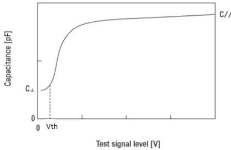
In terms of capacitance, it shall happen the same. When an electric field is turned on, the LC molecules orientation will change and by consequence the director will also change as was explained in figure 1.9. This will have contributions in capacitance values. Figure 1.15 shows how capacitance values can vary by an applied electric field in a LC device.29
The capacitance varies with director orientation. In figure C∥ represent the capacitance value parallel to the director and C⊥ the capacitance perpendicular to the director. This
happens because the ∥value is higher than ⊥, which means that for capacitances will happen
the same.
In a PDLC device with PME, when an electric field is applied, the director will turn par-allel to the distance between plates and, by consequence, the capacitance values will increase.
1.2.6.
Applications
PDLCs have a wide variety of applications due to their peculiar electro-optical and me-chanical properties. Such properties allow the use of PDLC in situations where other devices cannot be used. The most popular application for PDLC are the smart windows. Smart windows are composed by two conductive glasses, between theses glasses is placed a PDLC. Initially, the device is opaque, but with the application of an electric field the window switch to a transparent state.
PDLC Film-enabled glass can provide easily-controllable and security for both exterior windows and for interior glazing such as conference rooms or patient consultation rooms.30
Fig-ure 1.16 shows a PDLC application from Polytronix Glass Co., a company that makes Switcha-ble Glass Systems with PDLC films.
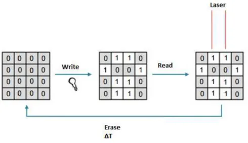
Figure 1. 17 - Write, read and erase information on a set of 16 PDLC cells device31Adapted
1.2.7
Write, read and erase information on a PDLC device
PME can be cleared when heat is applied. When the temperature is nearly the opaque-transparent state, the molecules of liquid crystal turn off their order of disposition and the memory transmittance disappears.
Information is written with the application of voltage to each PDLC unit independently, read by the optical response for each unit (opaque or transparent), and the written information erased using either a heating source or a higher frequency electric field for a dual frequency liq-uid crystal. Opaque and transparent stable states can be the base of a digital binary language where opaque state matches to 0 and transparent state to 1. That means, we can:
Write information - by applying an electric field,
Read written information - by opaque/transparent differentiation by using a laser, and Erase information - by heating the device until a temperature higher than Tc.
Figure 1. 17. shows a scheme of writing, reading and erasing in a PDLC on a set of 16 PDLC cells (2 bytes).31
This method can be very usefully on smart windows with PME displays. If a system can apply an electric field for turning the device transparent and heat the device with an electric cur-rent by joule-heating effect for returning to the opaque state, it can be very advantageous in terms of energetic waste.
The most advantageous way for controlling these parameters is by capacitance measur-ing. The capacitance variation along temperature can give more rigorous information than transmittance variation. In a smart window system it is more difficult controlling the transmit-tance than capacitransmit-tance and, actually, transmittransmit-tance curve can only show the jump between opaque and transparent states. Capacitance curve can also show this transition, has a trustworthy relationship with temperature variation and is easier to measure.
In this work, the method proposed for controlling the parameters in these systems con-sists in:
- Find the Tc by temperature variation, and which capacitance value matches it
- Write the information, this is, turn the device transparent with an electric field for a few seconds.
Chapter 2 - Materials and Methods
2.1. Materials
2.1.1. Liquid Crystal
–
E7
The E7 nematic liquid crystals mixture contains cyanobiphenyl and cyanoterphenol com-ponents made by Merck, at a specific composition, which possess relatively high birefringence and positive dielectric anisotropy. Due to these properties, it is widely used in polymer dis-persed liquid crystals. The specific composition is critical to ensure physical properties and characteristic of the liquid crystal, such as TNI higher than room temperature and a wide
appli-cable temperature range. Even small changes can have pronounced effects on factors such as the nematic to isotropic transition (TNI), and glass transition (Tg) temperatures.32
E7 is composted by four kinds of liquid crystals in different proportions that are de-scribed in table 2.1 32:
Table 2. 1 - E7 composition
Compound Structure
Tempera-ture Range (Nematic - Isotropic) Percentage (w/w)% 5CB 4-cyano-4'-n-pentyl-biphenyl
22-35ºC 51
7CB
4-cyano -4'-n-heptyl-biphenyl
28-42ºC 25
8OCB
4-cyano-4'-n-oxyoctyl – biphenyl
54-80ºC 16
5CT
4-cyano-4''-n- pentyl-p-terphenyl
130-239ºC 8
E7 is composted by four kinds of liquid crystals in different proportions. These liquid crystal have different structures and therefore the temperature range of nematic-isotropic transi-tion are not the same. It was necessary for the study cases the temperature be higher than room temperature. For those reasons, the E7 temperature of Nematic-Isotropic transition is about 58ºC.
E7 can be used in polymer dispersed liquid crystals, and it was used in all studies in this work, because it offers a wide range of operating temperatures in which it maintains anisotropic characteristics. The refractive indexes of E7 at T=20ºC are given as: no=1.5183, ne= 1.7378. The dielectric permittivity values of E7 at T=20ºC are given as: ⊥=18 x10-12 F m-1, ∥=7.5x10 -12 F m-1. It exhibits a nematic to isotropic transition at 58ºC and a nematic phase and no other
transitions between 58 and -62ºC, where it shows a glass temperature transition. 33 Therefore,
2.1.2. Oligomer and Initiator
Radical polymerisation was used in this work. This polymerisation consists in a reaction which a polymer forms by the successive addition of free radical building blocks, in this case the oligomer PEGDMA875. To make these reactions it was also needed an initiator that can discompose in free radicals and it will be the AIBN.
The oligomer PEGDMA875 (Polyethylene glycol dimethacrylate), from Aldrich has a molecular weight of 875g mol-1 and a density of 1.0135 g cm-3. Figure 2.1. shows the Oligomer
Molecule34:
The polymerisation is initiated through the use of agents capable of forming free radicals, which are referred to polymerisation initiator. The initiator was a thermal initiator, α,α -azobisisobutyronitrile (AIBN), from Sigma Aldrich, and it has a molecular weight of 164.21 g mol-1. When it heated, AIBN originates two free radicals and nitrogen (at T>64ºC). 35. Figure
2.2. shows the AIBN molecule
Figure 2. 1. – Oligomer PEGDMA87534
2.1.3 Radical Polymerisation
Steps of radical polymerisation.
There are three fundamental steps in radical polymerisation: initiation, propagation and termination. In the case of this polymerisation the initiator (I) will be the AIBN and the Mono-mer (M) will be the oligoMono-mer PEGDMA 875.
Initiation - Generation of free radicals (R·) by homolytic dissociation of the initiator (I).
Chain polymerisation reactions are different because an initiation step is needed to start the pol-ymer chain growth. Initiation can be achieved by adding a small amount of a chemical that de-composes easily to form free radicals.
Propagation - Chain extension by successive addition of monomer molecules (M) to the
monomer radical unities (Mn·) formed in the initiation step.
Termination:
2.1.4 PDLC preparation
The ratio liquid crystal/oligomer used was always 70/30 in all devices in this study. By the quantity of oligomer, a small quantity of initiator (1%) was dropped for inducing the polymerisation. All weights were measured in the analytical balance model AS 120/C/1 from RADWAG.
These mixtures were used directly in cells and it spreads completely their empty spaces by capillarity. The PDLC preparation was done slowly in a stove during night at 74ºC. This temperature ensures the formation of free radicals and then the polymerisation starting. Figure 2.3 shows the stove used for polymerisation.
2.2. Commercial and Handmade Cells
For this work two kinds of cells were used: LC2-20 commercial cells from Instec Co. and Handmade Cells made with conductive glasses made by Instec.
2.2.1. Alignment on Glass
Alignment layers are commonly used to align the liquid crystal molecules on substrates. In general, the LC alignment has to originate from symmetry breaking at the surface of the sub-strate. Asymmetries in either the macroscopic topographical or microscopic molecular structure of the substrate surface have been proposed for its origin. While a variety of methods can be used to determine the precise alignment direction of the LC molecules, even for monolayer films, it is more difficult to obtain detailed information regarding the molecular structure of the surface.37
Another important aspect of LC alignment is the origin of the so-called pretilt angle. The pretilt angle is of great technological importance in that it determines the gray scale contrast in LC displays.
The alignment can be divided into two major types: planar alignment, where LC mole-cules gain a parallel alignment and homeotropic alignment where LC molemole-cules align perpen-dicularly to the substrate glass. Figure 2.4. shows how this two types of alignment can align the molecules on glass substrate.
The planar alignment can be combed in a preferential direction by a technique called rub-bing. Rubbing consists in spread the substrate in one preferential direction for aligning the LC
Figure 2. 6 - Scheme of a commercial cell LC2-20 from INSTEC39
molecules. On cells, rubbing can have three alignment types: parallel, where both glasses have rubbing in same direction and way, anti-parallel, where both glasses have rubbing in same di-rection but different ways and perpendicular where glasses have perpendicular didi-rections. Fig-ure 2.5. shows this three sub-types of planar rubbing:38
2.2.2. Instec commercial cells
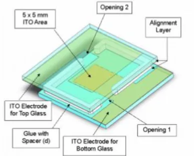
These commercial cells are made by two conductive glasses. The cells have a low parasit-ic capacitance, and the active area can be completely filled with the liquid crystal/oligomer ma-terial. The cell gap of each individual cell is 20 µm uniform to ±0.2 μm with 5x5mm ITO area in the middle of the cell and an anti-parallel alignment layer with 1º to 3º pre-tilted angle. The adhesive used in construction of these cells is rated to 200°C.39 Figure 2.6 shows an illustrative
scheme from a LC2-20 cell from Instec Inc.
2.2.3. Instec Glasses
Instec glasses sheets are conductivity glasses with Indium Tin Oxide (ITO) and a rubbing surface with polyimide (PI).40 These glasses have a size of 25mmx20mmx2.2mm and a sheet
resistance of 25ohm/sq. with a small frame which is non-conductive. They were used for made handmade cells in this work. Figure 2. 7 shows an illustrative figure of a substrate glass from Instec.
It is only known the rubbing direction on these glasses, there is no any information about the way: if the rubbing is from up to down or if it is from down to up. Then it was assumed that the glasses have the rubbing in same way and for making the handmade cells with different rub-bing types the frame side was the reference.
2.2.4. Handmade Cells
Handmade cells were made with Instec Glasses. The rubbing effect depends how these glasses are used to make a cell. The rubbing has some effect on the liquid crystal molecules, namely in their disposition near the surface
For cells with perpendicular rubbing the whole glass was used to prepare them. For mak-ing cells with parallel and anti-parallel rubbmak-ing the Instec glasses were coated in small parts to obtain the target rubbing configuration. Perpendicular Rubbing Cells have 4cm2 area and it was
made with the whole Instec glass. Parallel and Anti-Parallel rubbing cells have 1.5cm2 area and
they were made with coated glasses, one glass with 25mmx10mm and other with 20mmx15mm. For the spacing, two Mylar spacers with 23µ m of thickness were used. Figure 2.8 shows the three planar rubbing types used on this work.
Figure 2. 8 - Illustrative scheme of handmade cells with: a) Parallel; b) Anti-Parallel; and c) Perpendicular Rubbing
Cells without any alignment were also made (Only ITO) and with homeotropic align-ment. For these cells conductive glasses XY100T from Xinyan Technologic were used. These glasses have a 500mmx500mmx1.1mm size with an ITO coating and 100 ohm/sq of sheet re-sistance. For making cells, they were coated in the same proportions of Instec Glasses.
The homeotropic alignment cell was guaranteed with a lecithin layer. The procedure con-sisted in washing the ITO glasses first with an aqueous nitric acid solution 1:1 and then with ethanol. After washing, the glasses were standing on a desiccator during one day for drying. A lecithin solution with concentration 10g/L was prepared afterwards and the dry glasses were dripped in this suspension solution for 10 minutes. Then the glasses were standing on a desicca-tor during one day again, for drying.
Figure 2.9. shows a lecithin molecule used for homeotropic alignment:
2.3. Equipment
2.3.1. Measuring Capacitances - LCR Bridge
A Programmable LCR-Bridge from Hameg. Programmable LCR-Bridge HM8118 can
measure certain values from electric or a conductor display, namely capacitance, impedance, resistivity, inductance and respectively dissipation. In this study LCR-Bridge was used to meas-ure capacitances on cells. Figmeas-ure 2.10 shows the LCR-Bridge HM8118
Figure 2. 10 - LCR Programmable Bridge HM8118 system from Hameg41
Calibration
The Programmable LCR-Bridge HM8118 calibration can be done by two different man-ners: by open circuit calibration and by short circuit calibration. The open/short circuit calibra-tion compensates for the effects of parasitic impedances of the conneccalibra-tions to the component under test.
The LCR bridge HM8118 features a frequency range of 20 Hz to 200 kHz, in 69 steps, with a basic frequency accuracy of 100 ppm.41 Open circuit calibration was done with clips far
The frequency used for measuring capacitances was 1kHz and the sinusoidal voltage was 1V in all studies
2.3.2. Increasing and Decreasing Temperature - FP90 Central
Proces-sor
For controlling the temperature variation along the time, a thermoelectric heating (Peltier) system FP90 Central Processor Metler Toledo was used. FP90 can heat and cool with different temperature ratios and it has a temperature range between room temperature values and 375ºC.42
This equipment was used as a control temperature system for heat and cool the cells. Figure 2.12 shows the FP90 Central Processor.
Figure 2. 11 - Short Circuit for LCR Bridge Callibration41