AN IMPLEMENTATION OF A FRAMEWORK FOR COOPERATIVE ENGINEERING
Gil M. Gonçalves, Paulo Sousa Dias, António Santos, João Borges de Sousa, Fernando Lobo Pereira
{gil, pdias, ansantos, jtasso, flp}@fe.up.pt
Faculdade de Engenharia da Universidade do Porto Rua Dr. Roberto Frias s/n, 4200-465 Porto, Portugal
Abstract: This paper discusses a framework for Cooperative Engineering (CE) and its prototype implementation. Cooperative Engineering concerns the application of Concurrent Engineering techniques to the design and development of products and of their manufacturing systems by a network of companies coming together exclusively for that purpose. CE is a common practice in many industries such as automotive, aerospace, shipbuilding, defence, and pharmaceutical. This framework provides a formal model for CE. This is done in the context of distributed hybrid systems (DHS), a modelling and control framework for networked systems introduced recently by the control and computer science communities. Copyright © 2005 IFAC
Keywords: agile manufacturing, concurrent engineering, cooperation, manufacturing systems, systems engineering
1. INTRODUCTION
In this new world of alliances, partnerships are not an option but a requirement. Recent advances in computer and communication technologies, of which the Internet is an example, can lead to what Toffler (1991) entitled Adhocracies – highly flexible organisations composed of decentralized networks of independent entrepreneurs: typically, a network of companies (members) is formed to take advantage of a business opportunity which is beyond the reach of any single company on its own; the organizational model emerges from the ad-hoc networking of its members, where each member contributes its core competences in areas so distinct as engineering, manufacturing, marketing, or finance; each member is an independent system, with its own objectives and utility functions; the members of the network share goals and utility functions; decision-making takes place under partial information since each member protects its assets and know-how; the network is dissolved or evolves in some other direction when the business opportunity ceases. This organizational model differs from other inter-organizational models by the degree of shared
responsibility and by the structure through which partners contribute with their competences, using plug-in compatible business processes (van der Aalst and van Hee, 2002). This praxis is leading both to new business models and to the formalization of current practices. One such practice is Cooperative Engineering (CE). CE concerns the application of Concurrent Engineering to the concurrent design and development of products and of their manufacturing systems by a network of enterprises coming together exclusively for that purpose.
CE is illustrated with the design and production of the body of an automobile: one or more companies start an engineering process which involves a network of companies specialized in product engineering, manufacturing, marketing, design, etc.; the network develops the product (the car body) and the process (production line) in a coordinated fashion; the communication and coordination mechanisms are certified by the network for efficient operation; each company seeks to maximize its revenues; and the network seeks to maximize the quality of the body of the automobile and to minimize the time to market.
The nature of these networked organisations raises several challenges concerning formal models, structure and configuration, coordination and operation. A formal model of networked organizations should be able to capture the essential features of these systems namely the semantically rich concepts invoked by distributed computing. Partner selection is a resource allocation problem subject to tight temporal and informational constraints. Coordination and cooperation mechanisms (Campbell, 1987) guarantee the alignment of objectives and actions in the network and the efficient operation of the network.
This paper discusses a framework for CE and its prototype implementation. From control engineering, this framework has inherited the concepts of dynamic networks of hybrid automata, supervisory and decentralized control, and the motivation to improve the performance of increasingly complex processes. From computer science, this framework has incorporated event-driven state machine models, concurrent processes and object-oriented approaches. A case study from the VIDOP1 project (Gonçalves et
al., 2002) is used to illustrate the framework. The
goal of the project was to develop CE tools and technologies to compose an integrated model of a production facility from the models of its components (sub-models). The final result was an infrastructure for vendor integrated decentralized modelling (IVM) which includes a communication platform enabling co-operative work with clearly defined views for manufacturers and suppliers to transmit securely and quickly models (geometric models, process models, workflow models), machine programs, documentation, notifications etc.
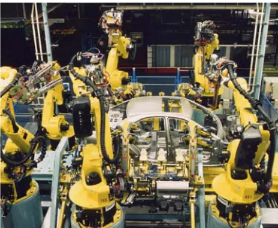
Fig. 1. Assembly cell in Sindelfingen (DE)
1
http://www.vidop.org. This project was funded by
the European Commission's "Competitive and Sustainable Growth" programme and was undertaken by a trans-European consortium, whose coordinator was KUKA Schweissanlagen GmbH. Participants included: DaimlerChrysler AG and University of Karlsruhe, Germany, INGEMAT, S. A. and
ROBOTIKER, Spain, University of Porto, Portugal, Tecnomatix, Israel, Imtech and Eindhoven
University of Technology, Netherlands, and Methodos S.p.A., Italy.
This paper is organized as follows. Section two describes an illustrative example to provide the motivation for our developments and introduces a brief description of the current practice. Section 3 presents a conceptual framework for Cooperative Engineering and section 4 its prototype implementation. Section 5 presents concluding remarks and discusses future developments.
2. MOTIVATION AND RELATED WORK The following example was adapted from a test case developed for the VIDOP project.
Part of the production line of the DaimlerChrysler (DC) body shop in Sindelfingen (Fig. 1) had to be re-engineered to produce a new product along with the existing ones (a different sunroof). The re-engineering project was split into several tasks, either according to the cells (components) that need to be modified (Fig. 2), or to the technologies involved in the process.
Fig. 2. Overall project structure (component view) Typically the OEM2, DaimlerChrysler in this case, contacts the original supplier of the existing line, mostly because this supplier has all the required information (specification, models, etc.). This fact precludes the OEM from selecting a different vendor from its pool of "technology" suppliers. In this example, the OEM started the re-engineering project and its networked organization by selecting KUKA, the supplier of the original line (see Fig. 3 for a description of this network). KUKA, acting as a turnkey supplier, selects sub suppliers 1 and 3 to take care of the redesign of cells 1 to 3 and of the handling system. In turn, suppliers 1 and 3 decided to split their task (this is their project) into additional subtasks. Each supplier selects from their own pool of "technology" providers the ones that best fit the tasks at hand.
Fig. 3. Overall project structure (company view)
2
Original Equipment Manufacturer
Turnkey supplier
Turnkey supplier
Supplier 1
Supplier 1 Supplier 2Supplier 2 Supplier 3Supplier 3
Sub supplie 31 Sub supplie 31 Supplier 4 Supplier 4 Sub supplier 32 & Sub supplier 33 Sub supplier 32 & Sub supplier 33 Sub supplier 11 Sub supplier 11 Sub supplier 12 Sub supplier 12 Turnkey supplier Turnkey supplier Supplier 1
Supplier 1 Supplier 2Supplier 2 Supplier 3Supplier 3
Sub supplie 31 Sub supplie 31 Supplier 4 Supplier 4 Sub supplier 32 & Sub supplier 33 Sub supplier 32 & Sub supplier 33 Sub supplier 11 Sub supplier 11 Sub supplier 12 Sub supplier 12 Line Line Cell 1
Cell 1 Cell 2Cell 2 Cell 3Cell 3
Robot Robot Handling Handling Guns Guns Robot Robot Stations Stations Line Line Cell 1
Cell 1 Cell 2Cell 2 Cell 3Cell 3
Robot Robot Handling Handling Guns Guns Robot Robot Stations Stations
The information and control flows in this networked organization are as follows. Information, drawings and models are exchanged on a need-to-know basis only. In this example, the OEM sends the necessary information (cell drawings, part drawings and new part parameters) to the turnkey supplier who, in turn, sends the information about cells 1 and 2 to suppliers 1 and 2, etc. Supplier 1 filters this information and sends partial models and drawings to its sub suppliers (11 and 12). Sub suppliers 32 and 33 receive the same information, possibly with different privileges. The case of supplier 4 is special. In order to redesign the handling system for the overall line, it needs information about the overall system. For example, it needs information about cells 1 to 3, but not in the level of detail needed to redesign the cells; it also needs updated information about the changes planned to cells 1, 2, and 3.
2.1 Generalisation
This illustrative example is a special case of the more general “Cooperative Plant Production” (CPP) scenario and of the “Phase and Role Model” (Woerner, et al., 2002). In this more general scenario, suitable for any Cooperative Engineering effort, several OEMs and several technology suppliers, which can also work as sub suppliers, are involved. These are classified either as Line Builders – suppliers of a complete line or cell, but also can work as turn key suppliers – or as Engineering
Houses - suppliers of partial solutions.
In the general CPP scenario the OEM can subcontract a project to one turnkey supplier (line builder), to several Line Builders (for different lines/cells), or to Engineering Houses (for lines designed by OEM). In the last two cases the OEM is responsible for project management. A Line Builder can work as supplier for different OEMs and, at the same time, as a turnkey supplier. It can also work as sub supplier of other Line Builders. The Line
Builders may also subcontract work to other Line Builders and Engineering Houses. An Engineering House can also play different roles in the CPP
scenario (see Fig. 4).
Fig. 4. Generalised Cooperative Plant Production The information and control flows in the CPP scenario pose requirements which go beyond current practice in traditional information systems. In the current practice, information potentially releasable to partners is often combined with other, sensitive data.
The unfortunate consequence is a denial of useful information to cooperating partners. Filtering information into small, coherent, and discrete packages (views) makes it easier to control and distribute to other members.
To support this operational concept a new paradigm to manage information in terms of standardized and discrete objects is required (Marmelstein, 2002). Such paradigm makes it possible to filter information objects from their sources, to publish, subscribe, query, and transform data objects, and to specify a policy governing the dissemination of and access to data objects. This paradigm leads to a structure of systems which manages, integrates, filters and distributes information to cooperating partners.
2.2 Current Approach
The problem of modelling and controlling networked systems has presented a new challenge to control and computer scientists. The challenge comes from the distributed nature of the problem. For example, in networked companies, information and commands are exchanged among multiple companies, and the roles, and dependencies of those companies change with time. The control and computer science communities address this challenge in the context of distributed hybrid systems, and contribute complementary views and techniques (see (Simsek,
et al., 2001) for an overview of research on
distributed hybrid systems).
Researchers in both communities have used Dynamic Networks of Hybrid Automata (DNHA) to model systems with evolving structure (Deshpande, et al., 1997). Informally, DNHA allow for interacting automata to create and destroy links among themselves and for the creation and destruction of automata. At the level of software implementation, this model has to incorporate the mechanisms by which software modules interact, which are called models of computation, or semantic frameworks. The choice of a model of computation for a specific implementation depends on the properties of the underlying problem domain (Edwards, et al., 1997). The problem of modelling systems with evolving structure is also discussed in (Milner, 1996). He argues that a rich conceptual development that gives a distinct character to the principles and concepts underlying computing, is in progress. In his claim, the distinct and unifying theme encompassing the new developments is what he calls "Information flow - not only the volume and quantity of flow, but the structure of the items which flow and the structure and the control of the flow itself". This is why Milner developed the Pi-calculus, an idealized modelling programming language and a mathematical model of processes whose interactions change with time (Milner, 1999). The Pi-calculus has been used to model service networks and other systems with evolving structure.
Problem formulations that model systems whose specifications are given as global constraints but whose solution is given by local controllers is investigated in the theory of decentralized supervisory control for discrete-event models (Rudie
OEM 1 Project: XC18
OEM 2 Project: Q class,
T class
Line Builder 1 Line Builder 2 Line Builder 3
Engineering House 1 Engineering House 2 Engineering House 3 Engineering House 4 Engineering House 5 Engineering House 6 OEM 1 Project: XC18 OEM 2 Project: Q class, T class
Line Builder 1 Line Builder 2 Line Builder 3
Engineering House 1 Engineering House 2 Engineering House 3 Engineering House 4 Engineering House 5 Engineering House 6
and Wonham, 1992). The problem with these formulations concerns the computational complexity of most decentralized discrete-event control problems (Tsitsiklis, 1989).
Today, there is no common software platform to support the implementation of a framework for CE across different projects in a cost-effective manner. This is especially true for small companies. In fact, the current practice concerns project-specific software platforms and does not encompass the methods and tools which could be used across different projects: i) communication flows are usually well defined but information management is project-dependant; and ii) communication is done through dedicated lines using costly proprietary platforms, which are common in big corporations. This practice makes it very difficult for small companies to enter and operate in a networked organization which would make them more capable to compete in a global market. Typically, these companies lack the methods and tools for access control and for secure and reliable information exchange which can significantly improve their capability to react to the requirements of a networked organization.
3. A FRAMEWORK FOR COOPERATIVE ENGINEERING
Based on the generalized Cooperative Engineering scenario, a supporting conceptual organisation can be derived. The proposed organisation is based on a hierarchical recursive structure. The OEM sets up a project, identifying a task and a partnership, (one in the case of a turnkey supplier) to several suppliers, to work on the project. In turn, each partner creates a new project based on his task. These new tasks are either executed in house or (sub) suppliers are contacted to deliver the product. All projects and tasks in the same tree are connected under a master-slave paradigm so that all of them can be synchronised at any time (e.g. due to project or task status change). Although these relationships can span several tiers, the complete tree is always invisible to any partner.
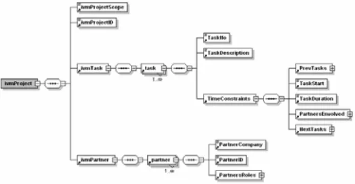
This organisation structure can be defined using an object oriented approach or using XML (eXtensible Markup Language). Figure 5 represents the XML schema representation for the presented conceptual organisation. Besides partners, tasks and their sequence, duration and precedence relations, companies and roles in the project, are also defined.
3.1 Required Functionalities
In order to support Cooperative Engineering, methods for the exchange of information and decisions have to be established. Some are set-up functions to establish and to manage cooperative work projects (defining projects, tasks and work items), but others include user functionality for managing work and information.
Cooperation support methods and rules can be divided in three groups:
- Cooperative work support methods.
- Workflow, work management and sharing methods. - Knowledge protection and security methods.
Cooperative support methods include groups of functionalities such as: file sharing; collaborative work & discussion; outliner; workflow definition and synchronization; and project management.
Fig. 5. CPP Schema
Besides specific cooperative work functionality, cooperation cannot exist without trust. The building blocks of trustworthy cooperation are methods for secure communication and for knowledge protection. This protection is realized by means of security, and data views methods. Based on a strong authentication and authorization, the system can define what the user is able to access and with what rights. It is mandatory that each partner is able to control his information as well as all the information that is coming from the hierarchical higher partner, addressing hierarchical lower partners.
4. IMPLEMENTATION
An implementation of the Cooperative Engineering Framework described in the previous section was developed under the VIDOP project. This prototype, called IVM (Infrastructure for Vendor integrated decentralised Modelling) already includes many of the characteristics of the proposed framework.
4.1 Architecture
The IVM is a distributed system that supports multiple, geographically distributed companies that are working together on a common project. The proposed architecture, made of loosely coupled modules, supports OEMs, turnkey suppliers, sub suppliers, as well as small engineering houses with limited resources. The IVM architecture is composed of several local IVMs representing the participating companies, all connected through a common communication platform. Each local IVM will offer services to its users. IVM services can be subdivided in generic and customisable services (Fig. 6). Examples of generic IVM services are uniform implementation of rules for secure transmission of information to remote users and uniform mechanisms for the implementation of view rights of models and documents directly at the source. Customisable services include services for locally defined project
management, project workflow, project model management including the access rights and others. The choice of technical architecture was based on the following high level requirements for the IVM: - It is a network of decentralized cooperating nodes. - The access to each node and the content of information published within that node is fully controlled by the node owner.
- The security mechanisms in the access and transmission over public networks prevent any unauthorized information access.
- Nodes installed on different platforms interoperate seamlessly.
- It is built using state-of-the-art and future oriented tools and artefacts, based on open standards.
In order to meet these requirements a Service Oriented Architecture was chosen among a number of alternative options to implement distributed object architectures. Web services were preferred because of two advantages:
- The SOAP protocol used in web services is more explicitly designed for internet applications than the IIOP protocol used in CORBA architectures.
- The interoperability of web services applications deployed in different run time containers is expected to be better than the interoperability of CORBA applications running in ORBs of different vendors. In order to make the data easy to manipulate XML was chosen. Besides the obvious interoperability, data can also be easily checked for conformance and validity (XML, 2004).
4.3 Components
The overall application architecture shows the components that make up the IVM communication platform. One of the highlights of this architecture is the possibility of spreading several components of an IVM installation node over different machines and environments, as long as they are all connected to the Internet. Each of the IVM components has a published web service into where requests (SOAP messages) are sent. All the web services URIs are stored in a configuration file. The depicted databases (Fig. 6) – IVM DB, MM DB, and Security DB – can be of any sort, from relational databases to XML databases (even file systems). The only requirement is that they must implement the storage interface in order to communicate with an IVM database. This database stores information related with the general working of the application and also with collaborative work and organisation. In some situations the information regarding collaborative work and organisation can be stored in a specific database (CW database).
The data objects (DOs) stored in this database are related with the organisation, project, relationship, task, authentication, authorization, messages and general data objects.
Presentation Layer (GUI). The decision taken about
the IVM client is that it should be a simple web browser. As a consequence, the Presentation Layer is a collection of dynamic web pages, constructed using the Java Server Pages (JSP) technology and the Apache Struts framework.
IVM Business Layer. The business layer is where all
business processes supported by the IVM are mapped onto. This layer controls the interactions between the various web services and the user. Internally, these business processes are mapped onto Struts action classes which are called when the server receives a request from the user through the GUI. Adding new business processes is fairly simple and without interfering with the rest of the system.
Gateway. Sends/receives requests from/to partner
companies. When the gateway receives a request, it decrypts the message and then verifies its authenticity (signature). When sending a request to a partner the gate encrypts and signs the message. This module is the proxy of all messages between IVMs.
Project WS. Receives requests from the local IVM,
and uses the Storage WS to store, retrieve and update project related objects (Organisation, Relationship, and Project) through the Storage WS.
IVM
Presentation Layer Gateway
Project WS Task WS Messenger WS Model Manageme Authorisat ion WS Authentica tion WS Storage WS IVM logic layer
Internal External MM DB Securi ty DB IVM DB Intranet Internet Firewall
Fig. 6. IVM architecture
Task WS. Receives requests from the local IVM, and
uses the Storage WS to store, retrieve and update task related objects (Task) through the Storage WS.
Messenger WS. Receives requests from the local
IVM, and uses the Storage WS to store, retrieve and update messenger related objects (messages) through the Storage WS.
Model Management WS. Receives requests from the
local IVM, and uses the Storage WS to store (check-in), retrieve (check-out) and update DOs (models). The MM WS uses its own Database to store model management related information
Authorisation WS. Receives requests from the local
IVM, and uses the Storage WS to retrieve Authorisation DOs (data objects) in order to execute the authorisation and filtering procedures.
Authentication WS. Receives requests from the logic
layer and from the Gateway to authenticate users and partner companies.
Storage WS. Works as a proxy to a selected database
(SQL, XML or file system) enabling other WS to store, retrieve and update objects. It capable of dealing with any kind of data objects (DOs).
4.4 Tools used in the development
In order to obtain portability for the IVM software Java was chosen for development. Versions of the Java virtual machine are available for all required OS platforms. First standards for SOAP handling are defined, which fit in existing Java concepts like the Java 2 Enterprise Edition (J2EE). Basic modules for rapid application development are available and developed further in open organisations like the Apache Project and the Java Community Process. The communication between different IVM nodes is implemented as web services based on the SOAP + attachment standard. Handling of SOAP messages is based on the standard JAX-RPC API (as implemented in frameworks like Apache Axis). Data structures in web method argument lists and return types as well as in implementation will be based on the following open source software:
- Apache Jakarta Tomcat for the Java Web container. - JBoss for the Java enterprise bean container. - Apache Axis, for the server side handling of SOAP RPC messages and the invocation of web service methods.
- JSP and the - Apache Struts framework (a variation of the classic Model-View-Controller – MVC) for the web browser user interfaces and the business logic invoking web methods in different IVM local nodes at client side.
- MySQL for IVM databases in the RDB flavour. - Apache Xindice for IVM databases in the XML flavour.
- Apache XML Security for the encryption and digital signatures.
- Dom4J, Apache Xerces and Apache Xalan for XML manipulation
5. CONCLUSIONS AND FUTURE WORK This paper presents the implementation of a framework for Cooperative Engineering based on a general framework of distributed hybrid systems. The proposed framework defines the interactions and responsibilities among the parties involved in Cooperative Engineering projects. Part of this work was developed in light of the VIDOP project, a trans-European project supported by the trans-European Commission's GROWTH Programme.
This framework was applied to case study drawn from the automotive industry. In this case study, the framework was mapped onto a platform to support the cooperative design and development of production facilities. In this Co-operative Engineering project, several suppliers are involved in a project to reengineer a body shop. This application is very helpful in showing the main advantages of the framework:
- Intra enterprise coordination and collaboration functionalities.
- Inter enterprise workflow interoperability functionalities.
- Co-operative work support methods. - Security and knowledge protection methods. - Faster interaction and document sharing.
A small description of the implementation is also discussed. The framework was implemented using Web technologies, like JAVA, XML, and SOAP. Currently, the main focus of research is moving onto the automatic selection (or evaluation) of potential partners and on the automatic definition of rules for cooperation (including operational rules - language and semantics - and business rules).
6. REFERENCES
Campbell, D., Resource Allocation Mechanisms, Cambridge University Press, 1987.
Edwards, S., L. Lavagno, E. Lee, and A. Sangiovanni-Vincentelli, Design of Embedded Systems: Formal Methods, Validation and Synthesis, Proc. IEEE, vol. 85 (n.3), March 1997, pp. 366-290.
Gonçalves, G., J. Sousa, F. Pereira, P. Dias and A. Santos, “A framework for e-cooperating business agents: An application to the (re)engineering of production facilities”, Proc.
Int. Conf. Advanced Production Management Systems, Eindhoven, NL, September 2002.
Marmelstein, R., Force Templates: A Blueprint for Coalition Interaction within an Infosphere, IEEE
Intelligent Systems, vol. 17, 2002, pp. 36-41.
Milner, R. (1996), Semantic ideas. In Computing
tomorrow: future research directions in computer science, Ian Wand and Robin Milner,
(ed.), pp. 246-283, Cambridge University Press. Milner, R., Communicating and mobile systems: the
Pi-calculus, Cambridge University Press, 1999.
Rudie, K, and Wonham, W. M. Think Globally, Act Locally: Decentralized Supervisory Control. IEEE Transactions on Automatic Control, vol. 37, N. 11, November 1992, pp. 1692-1708. Simsek, T., J. B. Sousa and P. Varaiya,
Communication and control in hybrid systems, (Tutorial session), Proc. American Control
Conference, Washington, US, June 2001.
Toffler, A., The Third Wave, Bantam Books, 1991. van der Aalst, W., and K.M. van Hee, Workflow
Management: Models, Methods, and Systems,
MIT press, Cambridge, MA, 2002.
Woerner, J., T. and Laengle and H. Woern, Corporate Planning and Simulation of Plant Production Facilities in the Virtual World, Proc.
18th Int. Conf. CAD/CAM, Robotics and Factories of the Future, Porto, Portugal, 2002,
pp. 109-116.
XML – Extensible Markup Language 1.0 (Third Edition), W3C Recommendation 4th February 2004, <http://www.w3c.org/TR/2004/REC-xml-20040204/> (February 2005)