Acknowledgement: Springer-Verlag
The original publication is available at www.springerlink.com: http://link.springer.com/chapter/10.1007%2F978-3-319-16486-1_8
A Structural Prototype for Planning and
Controlling a Manufacturing System
Paulo Enes Silveira1,2
1 Universidade Autónoma de Lisboa, Departamento de Ciências e Tecnologias, Rua de Santa Marta, 47, 1150-293, Lisboa, Portugal
2 Universidade Lusíada de Lisboa, Rua da Junqueira, 188, 1349-001, Lisboa, Portugal [email protected]
Abstract. Structuring the information and knowledge needed to implement a factory, as well as doing its control and management by computer systems, is the purpose of the meta-model and solutions here presented.
This meta-model includes: an object-oriented model to structure the needed information and knowledge; a model for manufacturing systems; a prototype that integrates the two previously referred models with real time control, in order to plan and to realize the management of a factory.
A first step of this work has been accomplished at the Ephestia Kuehniella Bio-factory, controlled by computer in the Laboratory of the Biology Department at the University of Azores.
In this paper we present a meta-model for a factory planning, controlling and managing, with updated conceptual and technological options, preparing the way for a new industrial implementation of the above mentioned Biofactory.
Keywords: Information, Knowledge, CIMS-Computer Integrated Manufacturing System, Biofactory, Real-time Management, Planning, Controlling, Object-Oriented, HBDS, GRAI, Prototype
1 Introduction
The Biology Department at the University of Azores holds a production unit in a laboratory environment, a biofactory that has been producing Ephestia Kuehniella Zeller eggs. This “Mediterranean flour moth” works as an intermediate host for multiplication of Trichogramma, a parasitoid used in biological control, to avoid the use of pesticides in agriculture [1].
This Biofactory patented by J. Tavares and described in [2] has been through several improvements. One of them, occurring in a period where it was producing with a computer and instrumental system, a software and hardware solution controlling the Biofactory in real-time, which we designed and implemented [3].
The advantage of this system is that all tasks can be automatically performed, minimizing human presence in the compartments where the activity of Ephestia
2 adults (little butterflies) can be harmful to human beings, due to a micro powder released by their wings.
To structure the information and knowledge needed for a manufacturing system, the object-oriented technologies has been widely used in automated manufacturing models [7], process planning, manufacturing activities and resources [8][9], as well as Petri nets for planning and controlling manufacturing activities [10]. The integration of several models is usually made for efficient manufacturing systems.
As we needed to plan, implement and control this Biofactory by a computer system, we decided to use the following models: the HBDS (Hypergraph-Based Data Structure) [5], an object-oriented model for structuring data from the information about the Biofactory and its environment; Operators associated to the HBDS Abstract Data Types (HBDS-ADT) [4], that we have conceived and built to control and act on the HBDS-ADT; the GRAI (Graphs with Results and Activities Interrelated) model [6], for the manufacturing system. We have also integrated the GRAI within the HBDS, so that the Biofactory activities could be represented in the HBDS context [3]. This Ephestia Biofactory that can produce an average of three million eggs per day [2] is still producing in a laboratory environment for R&D needs, at the above mentioned Biology Department, but its control system by computer has already become obsolete and is not working nowadays.
In the same Department, a project is being analyzed in order to build a new Biofactory for industrial production. In this context, we here summarize the results obtained in the first stage of the Biofactory for R&D, and point out a Meta-model for planning, controlling and managing, with updated conceptual and technological solutions to be prepared for the new industrial production unit.
In the remaining of this paper, section 2 presents how to structure the information needed for the manufacturing system, the said Biofactory, with the HBDS model, showing its application to a Biofactory partial structure. Section 3 is dedicated to the knowledge on the manufacturing system, presenting the concept Operator associated to the HBDS-ADT and defining some of these Operators on the Biofactory. Section 4 reveal the GRAI model for manufacturing systems applied to some Biofactory activities. The main contribution of this paper is presented in section 5: a Structural Prototype for planning and controlling a manufacturing system in real time and its application to the Biofactory. Section 6 points out the new solutions for computer control of the under study Biofactory industrial unit and Section 7 sets the conclusions.
2 Structuring the information needed for the Bio factory
2.1 Introduction to the HBDS model
3 We have discussed the advantages of the HBDS model used for structuring the information needed for the Biofactory in [3] and [4]. Its mathematical basis, the Hypergraph and Graph concepts, its notions of Object-Oriented (OO) inspired by SIMULA of Ole-Johan Dahl and Kristen Nygard1, and its graphic representation
capacities made HBDS a better model than the ER (Entity Relationship) or the UML Class Diagram, being able to represent complex phenomena and to avoid redundancy. The HBDS model is widely explained in [4], but here are pointed out the main components used on the Biofactory analysis, which are six HBDS-ADT: three ADT, Class (C), Class Attribute (A) and Link between Classes (L), representing a set, a property and a relation on the phenomena being analyzed, which are the abstract conceptual components; another three ADT, Object (O), attribute (a) and link between two elements (l), representing a set element, a property value and a relation between two elements, in fact the components that materialize the conceptual ones.
This model have also some ADT extensions for meta-representation: Hyperclass (HC) grouping Classes with common Attributes; Hyperattribute (HA) for the mentioned common Attributes; Hyperlink (HL) that get together Links between Classes included in two Hyperclasses; Multilink (ML) that groups Links between Classes.
A graph tree structure represents the hierarchies between Classes and also between Hyperclasses.
The possible operations on the HBDS-ADT are: Create and Eliminate, Modify, Destroy and Recover, Hibernate and Rise. They can all be written through a specific HBDS-ADT syntax.
2.2 The Biofactory structure
The description of the Biofactory data structure actually existing in laboratorial version is detailed in [3]. Let us now focus on a part of this structure where some knowledge on dynamic behavior has to be associated.
The names of the Classes and Hyperclasses are in uppercase. Links between Classes appear in lower case and the Attributes with the first character uppercase.
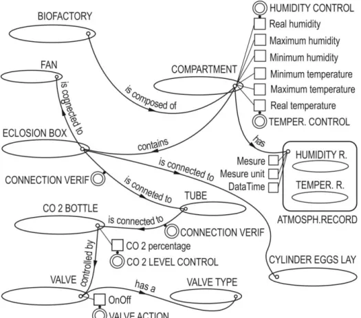
As shown on Fig. 1, the BIOFACTORY ‘is composed of’ COMPARTMENT. A COMPARTMENT contains an ECLOSION BOX which ‘is connected to’ a TUBE and this one ‘is connected to’ a CO2 BOTTLE ‘controlled by’ a VALVE that ‘has a’ certain VALVE TYPE. Also, an ECLOSION BOX ‘is connected to’ a FAN that can inject a stream of air, forcing the asleep Ephestia butterflies to pass from the ECLOSION BOX to the CYLINDER EGGS LAY.
Some of the Attributes are described with the HBDS-ADT syntax presented in [4]. The compartment humidity and temperature are: COMPARTMENT•Real humidity; COMPARTMENT•Maximum humidity; COMPARTMENT•Minimum humidity’. The same occurs with the temperature Attributes.
A COMPARTMENT has an ATMOSPHERIC RECORD, which is a Hyperclass, with the included Classes HUMIDITY RECORD and TEMPERATURE RECORD.
1 Both Ole-Johan Dahl and Kristen Nygard received the ACM A. M. Turing Award in 2002, for their contribution to OO Programming.
4 Three Hyperattributes are ATMOSPHERIC RECORDS•Measure, ATMOSPHERIC RECORDS•Measure unity and ATMOSPHERIC
RECORDS•DateTime. A CO2 BOTTLE is responsible for injecting some CO2 in the eclosion box, where
the Ephestia in their adult state (as butterflies) are, ensuring they will fall asleep, to force their transition into the CYLINDER EGGS LAY. The Attributes CO2 BOTTLE•CO2 percentage and VALVE•OnOff mode shows, respectively, the amount of gas available in the bottle and the valve in on/off mode, which indicates whether the gas is passing or not passing.
3
Knowledge on the manufacturing system
3.1 How to associate knowledge to the ADT
Some knowledge can be added to HBDS-ADT by Operators associated to each of the six HBDS-ADT. We proposed these Operators in [4]. They contain a set of conditions and actions which can be fired automatically whenever an ADT state changes.
An Operator associated to a HBDS-ADT (O•ADT) is defined as a five tuple: <O•ADT> ::= (<type of O> , <associated ADT name> , <before | after> , <operations>, <programming code reference>). (1) This O•ADT definition has five components: the type of Operator (element-type or set-type); the associated ADT name (names of C, A, L, O, a, l); acting before or after the operations on the ADT, and also a reference to the Operator programming code (its conditions and actions).
When an O•ADT is associated to an Object Attribute it must be a dynamic attribute (changing its value along time). It is the value modification of this attribute that fires the Operator execution.
The O•ADT graphic representation, detailed in [4], is usually represented by two concentric circles with an association point.
3.2 Knowledge management at the Biofactory
We shall now define some O•ADT on the Biofactory HBDS, represented in Fig. 1: HUMIDITY CONTROL. This Operator is an O•Aa of set-type acting after the operation Modify on the value of the Object attribute:
HUMIDITY CONTROL ≈ (O•Aa, COMPARTMENT•Real Humidity, after, Modify, HUMIDITY CONTROL( ) ). (2)
5 The definition (2) shows the O•Aa five components, the last one being the reference to the HUMIDITY CONTROL( ) code.
This code controls the real humidity, keeping it between the maximum and minimum humidity, by turning OFF or ON the heater and the refrigerator units. The Operator code is automatically executed when a value modification happens in the COMPARTMENT•Real Humidity.
TEMPERATURE CONTROL. Identical definition for this O•Aa, like the one we provided for the HUMIDITY CONTROL Operator.
VALVE ACTION. This one is an O•Aa of set-type, acting before the operation Modify on the value (On or Off) of the VALVE Object attribute:
VALVE ACTION ≈ (O•Aa, VALVE•OnOff, before, Modify,
VALVE ACTION( )). (3) If a valve named v1 is controlling the CO2 gas entering the eclosion box eb1, the VALVE ACTION( ) code will be executed, the moment the v1[VALVE]•OnOff is modified to ‘On’ or to ‘Off’.
6 This code has the conditions and actions of its Operator: it verifies the opening or closing state of the eclosion box window, closing it when the gas is injected, or opening it when the gas injection stops. It also controls the fan that injects a stream of air into the eclosion box, when the gas injection comes to an end.
CONNECTION VERIF. The CO2 BOTTLE ‘is connected to a’ TUBE. The ADT Link ‘is connected to’ has an O•Ll of set-type2 acting after the operation Modify on the link realization3:
CONNECTION VERIF ≈ (O•Ll, CO2 BOTTLE ‘is connected to a’ TUBE, after, Modify, CONNECTION VERIF( ) ). (4)
Whenever the link between the bottle b1 and the tube t1 becomes ‘false’:
b1[CO2 BOTTLE] ‘is connected to a’ t1[TUBE] ← FALSE (5) then, the CONNECTION_VERIF( ) code is executed after the modification, through its conditions and actions, sending an alarm signalizing the fail of the connection that may cause a gas leakage and closing the valve of the CO2 bottle.
Other O•ADT. Many other Operators O•ADT are used on the Biofactory knowledge structure. They contain some knowledge about the Biofactory behavior, which allows them to act automatically, depending on the change of Biofactory state.
4
Planning the manufacturing activities
4.1 The GRAI model
The GRAI (Graphs with Results and Activities Interrelated) [6] is a model for Computer Integrated Manufacturing Systems that defines a manufacturing activity by the Category Theory assuring a mathematical consistence. One activity ki belongs to the actions category Cat-K (ki ∈ K):
ki = (qi-1, xi, αi, qi, βi, yi). (6) where qi-1: pre-activity sate; xi: resource or entry, αi: activity or morphism, qi: post-activity state or result, βi: morphism measures, yi: output or measure results.
2 The set-type Operator O•Ll is associated to the L-Link between Classes, acting on the realizations of l-link between Objects
3 Modifying a l-link between Objects, means to validate it ‘true’ when the link exits between tow Objects, and to validate it ‘false’ when the same link becomes null.
7 The activity αi is performed when the pre-activity state qi-1 is validated and the resources or entries xi are confirmed. Once the activity completed, the post-state qi is validated, preparing the way for the next activity.
Other aspects of the GRAI through the Category Theory can be observed in [3]. 4.2 The Biofactory production activities
In Fig. 2 we draw, in a GRAI graphical form, a part of the Biofactory production chain, with the activities: α1 - Acting valve1 to close the eclosion box window; α2 - Placing the cylinder eggs lay in the receiver; α3 - Placing the shake fork connecting
Fig. 2. Biofactory partial GRAI activities
the motor to the eclosion box; α4 - Acting valve0 for CO2 injection. The activities α2 and α3 can be done in parallel.
The resources or entries for these activities are: α1: x1.1 - The eclosion box window opened, x1.2 - Order to act valve1; α2: x2.1 - The cylinder eggs lay, x2.2 - The receiver ready to receive the cylinder eggs lay; α3: x3.1 - The shake fork; α4: x4.1 - The CO2 bottle, x4.2 - Order to act the valve0, x4.3 - Δt time interval for CO2 injection.
Each activity (act) has a pre-act state and a post-act state or result: α1 pre-act:q1 - Adult Ephestia (butterfly) after its pupa state; α1 post-act and α2 pre-act: q2 - Butterflies in the eclosion box with closed window; α2 post-act and α3 pre-act:q3 - Eclosion box ready for CO2 injection; α4 post-act:q4 – Asleep butterflies.
8
5
A Structural Prototype for planning and controlling a
manufacturing system
5.1 Building the Prototype
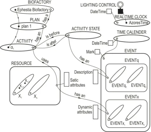
Fig. 3 shows two main classes, PLAN and ACTIVITY (the αi from the GRAI ki definition (6)). The ACTIVITY has ACTIVITY STATE (q) and uses RESOURCE (x).
Fig. 3. Structural Prototype for planning and controlling a manufacturing system, with a partial example of the Ephestia Biofactory
These activity states and the resources have EVENTq and EVENTx that happen along the manufacturing process.
The Hyperclass EVENT contains the Hyperclasses EVENTq (that, by its turn, contains the Classes EVENTqi, for the realizations of the i event-state) and EVENTx (that contains the Classes EVENTxi, for the realizations of the i event-resource).
9 The Attribute EVENTqi•Mark is validated with a mark, when the activity αi can be performed verifying that the event-resources Attributes EVENTxi•Mark are marked as ready. When one of these events is marked ready, the moment is registered with an associated object ti of the class TIME CALENDER.
The Class REAL TIME CLOCK, has Objects representing different world times. An element operator O•aa associated to the Object Attribute <obj>[REAL TIME CLOK]•DataTime can act controlling every operation needed.
The set of Hyperclasses and Classes represented in Fig. 3 form a new Structural Prototype for planning and controlling a manufacturing system.
5.2 Applying the Structural Prototype to the Biofactory
The Class BIOFACTORY ‘has a’ Link with the Class PLAN. The Object ‘Ephestia Biofactory’ materializes this Link with the Object ‘plan 1’:
EphestiaBiofactory[BIOFACTORY] ‘has a’ plan1[PLAN] (7) The plan1 PLAN has seventeen Objects (α1,…,α17) belonging to the Class ACTIVITY, of which the first one is:
plan 1[PLAN] ‘has an’ α1[ACTIVITY] (8) These seventeen activities use about thirty resources, distributed by seventeen resources Classes, X1 … X17, contained in the Hyperclass RESOURCE. As we can see in Fig. 3, the activity α1 has two resources, x1.1 and x1.2:
α1[ACTIVITY] uses x1.1[X1] (9) α1[ACTIVITY] uses x1.2[X1] (10)
The Biofactory has a lighting system to simulate day and night, like a normal day in nature. This system is controlled by an element-type Operator O•aa associated to the Object attribute DateTime of the Object AzoresTime belonging to the Class ‘REAL TIME CLOK’:
LIGHTING CONTROL ≈ (O•aa, AzoresTime[REAL TIME CLOK]•DateTime after, Modify, LIGHTING CONTROL()). (11)
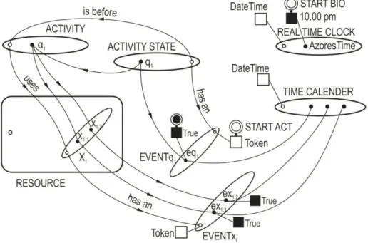
The life-cycle of the Ephestia Kuehniella in the Biofactory begins with first activity, already in pupa state, ending with the egg state.
Fig. 4 illustrates the starting of the Biofactory, showing the instantiation of Objects and Operators O•ADT in the Structural Prototype needed to begin the first activity α1 - Acting valve1 to close the eclosion box window. Assuming that the Biofactory production starts at 10:00 p.m., Azores time, the START BIO Operator, similar to the LIGHTING CONTROL defined in (11), fires when the attribute AzoresTime[REAL TIME CLOCK]•DataTime = 10:0 p.m., running the following set of operations: 1.
10 Checks the resources that α1 uses, x1.1[X1] and x1.2[X1], creating the Objects in the Class EVENTx1, ex1.1[EVENTx1] and ex1.2[EVENTx1], and modifying their attributes Token to TRUE, the moment these resources get ready; 2. When all these Token attributes are TRUE, than the Object eq1[EVENTq1] is created and its attribute Token modified becomes TRUE, firing the Operator O•Aa STRAT ACT associated to the attribute [EVENTq1]•Token, similar to the Operator defined in (2); 3. The START ACT Operator starts the activity α1, than beginning the Biofactory production.
When α1[ACTIVITY] is finished, a new similar set of operations runs for α2[ACTIVITY]and all other activities of the Biofactory[PLAN], thus completing the manufacturing cycle.
Fig. 4. Biofactory automatic start with the activity α1
6 New solutions for computer control of the Biofactory industrial
unit
The first solution for this Biofactory controlled by computer, has worked with a hardware system programmed in Instrumental Basic, both from Hewlett Packard.
There were no planning and managing interface to the interaction with the Biofactory. All the conceptual model has been implemented to send and receive data and signals, with instruments (such as valves, thermometers, hygrometers and switches) and their programming for controlling the Ephestia Biofactory.
11 With the new project under study for an industrial unit of the Biofactory, at the Biology Department at the University of Azores, we plan to build a Computer Integrated Manufacturing System, by implementing the Structural Prototype for planning and controlling a manufacturing system, presented in the previous point.
The interfaces for managing the Biofactory can be performed, either by a computer, by a laptop or a by mobile device, with the advantage of minimizing human presence inside of the Biofactory, as it was already said in the introduction.
7 Conclusions
This paper has summarized the first step of the described Ephestia Biofactory controlled by computer. The conceptual models used, the HBDS and GRAI, with its output solutions has been presented.
The proposed Operators associated to the HBSD-Abstract Data Types, O•ADT, contribute to include knowledge in the representative structure of the domain under consideration, the Biofactory, allowing for automatic actuation on the system, under the conditions and consequent actions of each O•ADT, which can be triggered by the state change of system itself. Some examples of these Operators were shown, acting on the Biofactory.
We have proposed an Oriented-Object Structural Prototype for planning and controlling a manufacturing system, from witch we instantiate a plan of the Biofactory activities, with their states and resources. A Hyperclass of events takes into account all these occurrences of states and resources in real time (classes TIME CALENDER and REAL TIME CLOK). To make clear how it works, the starting of the Biofactory cycle production was detailed, showing how all its activities can be performed.
A new project for an industrial unit of the Biofactory is being studied at the Biology Department at the University of Azores. In this context, we are working in an implementation of a Framework for Computer Integrated Manufacturing System including the proposed meta-model, the Structural Prototype integrating HBDS and GRAI, for planning and controlling a manufacturing system.
References
1. Vieira, V., Falp, L., Tavares, J.: Epigenetic variability of Ephestia kuehniella Zeller (Lepidoptera, Pyralidae) under Mass Rearing Conditions. In:Avances en Entomología Ibérica (ed. Comité editorial). Museo Nacional de Ciencias Naturales (CSIC) y Universidad Autónoma de Madrid: 491--500 (1995)
2. Tavares, J., Vieira, V.: Produção em Massa de Ephestia Kuehniella Zeller (Lep. Pyralidae) IV Técnicas de Recolha dos Adultos e ovos. Açoreana, Revista de Estudos Açoreanos, 7(3): 461--470 (1992)
12 3. Silveira, P. E.: Estrutura de Dados Dinâmica. Aplicação à Gestão e Controlo em Tempo Real, de uma Biofábrica, por Computador. Revista de Ciência e Cultura, Série de Matemáticas Aplicadas, n.2 Universidade Lusíada, 107--140 (1997)
4. Silveira, P. E.: Componentes de Conhecimento em Estruturas de Dados Persistentes. Aplicação em Sistemas de Decisão Autónomos. Dossier: Novos Modelos TIC na Resolução de Problemas Reais, Economia & Empresa. N. 10/2010, Universidade Lusíada, Lisboa, 11--39 (2010)
5. Bouillé, F.: Object-Oriented Methodology in Environment GIS Studies, Intercarto International Conference on GIS Environment Studying and Mapping, Moscouv, 10, (1994) 6. Pun, L.: Integrated Discrete Production Control: Analysis and Synthesis: A View Based on
Grai-Nets, Elsevier, Amsterdam (1992)
7. Park, T.Y., Han, K.H., Choi, B.K.: An Object-Oriented Modelling Framework for Automated Manufacturing System. In: International Journal for Computer Integrated Manufacturing, 1997, 10, 5, 324--334 (1997)
8. Pullan, T., Bhasi, M., Madhu, G.: Object-oriented modelling of manufacturing information system for collaborative design. In: International Journal of Production Research 50, 12 3328--3344 (2012)
9. Kowal, M., Legat, C., Lorefice, D., Prehofer, C., Schaefer, I., Vogel-Heuser, B.: 2014. Delta modeling for variant-rich and evolving manufacturing systems. In: Proceedings of the 1st International Workshop on Modern Software Engineering Methods for Industrial Automation, ACM, New York, 32--41 (2014)
10.Zhang, L., Xu, Q., Helo, P.,: A Methodology Integrating Petri Nets and Knowledge-Based Systems to Support Process Family Planning. In: International Journal of Production Research, 50, 12, 3192--3210 (2012)