UNIVERSIDADE DA BEIRA INTERIOR
Engenharia
Sizing Analysis of a Battery System for an
Electrically-Propelled Airplane
Micael Valverde Teixeira
Dissertação para obtenção do Grau de Mestre em
Engenharia Aeronáutica
(ciclo de estudos integrado)
(versão revista após discussão)
Orientador: Prof. Doutor Francisco Miguel Ribeiro Proença Brojo
iii
Acknowledgments
To my parents, which have always showed their unconditional support and love to me through all my life, inspiring me to be the man I am today and, for giving me every single opportunity to enrich my life with different experiences.
To my littles sister, that brought love to my life and, made me the happiest brother ever since. To all my friends and colleagues, with which I shared these amazing six years in university and were always there side-by-side with me whenever I needed someone.
A special thanks to Daniela Ribeiro, the never-ending support and sacrifices made by her were much apreciated and will not soon be forgotten.
I would also like to extend my gratitude to my landlords, who took me in and offered me everything I needed throught my years in university.
Finally I would like to thank my thesis advisor, professor Francisco Brojo, for giving me the opportunity to realize this thesis and, giving me all assistance needed to accomplish it.
v
Resumo
O conceito de propulsão elétrica tem provado ao longo das últimas décadas que pode ser uma boa solução para substituir os motores de combustão interna em aviões, a fim de criar uma maneira mais eficiente, ambientalmente amigável e confiável de viajar através do ar. Mas ainda não foi capaz de atingir seu potencial devido a muitas limitações com as tecnologias ativas de hoje, principalmente as baterias. Várias empresas já começaram a equipar alguns modelos de aviões com motores elétricos e uma fonte de energia de bateria e usá-los como bancos de ensaio para futuras pesquisas e desenvolvimento de conceitos de propulsão elétrica. Como a maioria dessas empresas tende a tornar confidencial a informação sobre esse assunto devido à sua relevância na atualidade, foi desenvolvido um algoritmo capaz de usar os atuais métodos conceituais de projeto de avião e usar dados históricos para prever e avaliar o dimensionamento de um sistema de bateria para uma configuração de avião com propulsão elétrica. Como era de se esperar, o algoritmo mostrou que, com a atual tecnologia de baterias, os aviões movidos a eletricidade ainda estão longe de competir com seus equivalentes de motores de combustão interna. Ainda assim, as próximas décadas prometem ser instrumentais para o conceito de propulsão elétrica se afirmar no mercado de aviação.
Palavras-Chave
Propulsão elétrica, aviões com propulsão elétrica, tecnologia de baterias, propulsão distribuída, propulsão elétrica híbrida.
vii
Abstract
The electric propulsion concept has proven over the past decades that it can be a good solution to substitute internal combustion engines in airplanes in order to create a more efficient, environmentally friendly and reliable way of travelling through air. Still it has not been able to reach its potential due to many limitations with today’s active technologies, mainly the batteries. Several companies have already started to outfit some airplane models with electric motors and a battery power source and use them as test beds for future research and development of electric propulsion concepts. Since most of this companies tend to make information regarding this subject confidential due to its relevancy in today’s age, an algorithm was developed, that is capable of using current conceptual airplane design methods and use historical data to predict and evaluate the sizing of a battery powered system for an electrically-propelled airplane configuration. As is was expected, the algorithm showed that with current battery technology, electrically-propelled airplanes are still far from being able to compete with their internal combustion engine counterparts. Still the next decades should prove to be instrumental for the electrical propulsion concept to assert itself in the aviation market.
Keywords
Electrical Propulsion, electrically-propelled airplanes, battery technology, distributed propulsion, hybrid-electric propulsion.
ix
Index
Acknowledgments ... iii Resumo ... v Abstract... vii List of Figures ... xiList of Acronyms ... xix
List of Chemical Elements ... xxi
1. Introduction ... 1
1.1 Motivation ... 1
1.2 Objectives of this Dissertation ... 3
1.3 Organization of Thesis ... 4
2. State-of-Art ... 5
2.1 Brief History of Electric Propulsion in Aviation ... 5
2.2 Current Electrically-Propelled Airplane Landscape ... 8
2.3 The Barriers to Electrical Propulsion ... 10
2.3.1 Market Demand ... 11
2.3.2 Battery Performance ... 11
2.3.3 Fuel Cells Performance ... 16
2.3.4 Solar Power Performance ... 18
2.3.5 High Power Density Generators and Motors ... 20
2.3.6 New Airplane Architecture ... 20
2.3.7 Regulation ... 21
3. Case Study ... 23
3.1 Selection of the Airplane ... 23
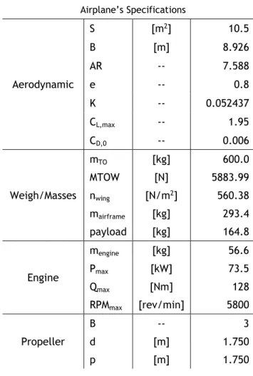
3.2 Airplane’s Specifications and Performance... 23
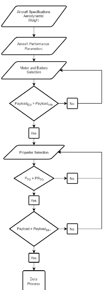
3.3 Numerical Model Thought Process ... 25
3.4 Numerical Model Development ... 27
x
3.4.2 Motor and Battery Model Selection Function ... 30
3.4.3 Performance Estimation Function ... 33
3.4.4 Propeller Selection Function ... 35
3.4.5 Performance Function ... 44
3.4.6 Data Processing and Mission Profile Functions ... 46
4. Results ... 47
4.1 Results ... 47
5. Conclusions and Future Work... 57
5.1 Conclusions ... 57
5.2 Future Work ... 57
References ... 59
Appendix A: Table of Results ... 65
xi
List of Figures
Figure 1.1: Total World CO2 emissions from fuel combustion from 1971 to 2015 [1]. ... 1
Figure 1.2: Trend in emissions of air pollutants from transports [2]. ... 2
Figure 1.3: Contribution of the transport sector to total emissions of the main air pollutants, 2015 [2]. ... 2
Figure 2.1: Electric Propulsion parallel hybrid architecture schematic... 7
Figure 2.2: Electric Propulsion series hybrid architecture schematic. ... 7
Figure 2.3: Electric Propulsion turbo-electric architecture schematic. ... 7
Figure 2.4: Electric Propulsion all-electric architecture schematic. ... 7
Figure 2.5: Battery cell process of operation [28]. ... 12
Figure 2.6: Fuel cell process of operation [28]. ... 16
Figure 3.1: Numerical process design. ... 26
Figure 3.2: EMRAX 208 schematics and views [52]. ... 32
Figure 3.3: Blade division into subsections, taken from [54]. ... 35
Figure 3.4: Blade flow components, taken from [54]. ... 36
Figure 3.5: Side view of a typical stream tube of flow passing through a blade section, taken from [54]... 37
Figure 3.6: Front view of a typical streamtube of flow passing through a blade section, taken from [54]... 38
Figure 4.1: Thrust vs Airspeed graph. ... 49
Figure 4.2: Power vs Airspeed graph. ... 50
Figure 4.3: Thrust and Power Coefficients vs Advance Ratio graph. ... 51
Figure 4.4: Porpeller’s Efficiency and Power Coefficient vs Advance Ratio graph. ... 51
Figure 4.5: Rate of Climb vs Airspeed graph. ... 52
Figure 4.6: Rate of Descent vs Airspeed graph. ... 53
xii
Figure 4.8: ICE and EM Mass Distribution. ... 55 Figure 4.9: ICE and EM Total Mass. ... 55 Figure 4.10: Mission Profile graph. ... 56
xiii
List of Tables
Table 2.1: Primary lithium battery specifications [39]. ... 15
Table 2.2: Secondary lithium battery specifications [39]. ... 15
Table 3.1: Dynamic WT9 ICE configuration specifications... 24
Table 3.2: Dynamic WT9 ICE configuration performances... 24
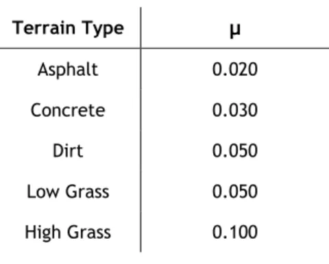
Table 3.3: Terrain Friction Coefficients. ... 29
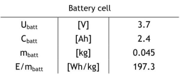
Table 3.4: LiCoO2 battery specifications (model 18650). ... 30
Table 3.5: EMRAX 208 specifications [51]. . ... 32
Table 4.1: Initial Battery System Sizing used for reference. ... 48
Table 4.2: Chosen propeller properties. ... 48
xv
Nomenclature
a1 Axial Inflow Factor
a2 Angular Inflow Factor
AR Wing Aspect Ratio
b Wing span
B Number of Blades of Propeller
c Blades Chord
Cbatt Battery Capacity
CD Drag Coefficient
CD,0 Drag coefficient at Zero Lift
CL Lift Coefficient
CL,max Maximum Lift Coefficient
Cp,prop Propeller’s Power Coefficient
Cq,prop Propeller’s Torque Coefficient
Ct,prop Propeller’s Thrust Coefficient
d Blade’s Diameter
D Drag
e Oswald Wing Efficiency Factor
E Lift to Drag Ratio
EClimb Energy Needed During Climb
Ecruise Energy Needed During Cruise
Edescent Energy needed During Gliding
Endurance Airplane’s Achivable Endurance ETO Energy Needed During Take-off
E / mbatt Battery Specific Energy
g Acceleration due to gravity hmax Absolute Ceiling
hOA Cruise Ceiling
hTO Take-off Altitude
H Straight Line Ceiling Imotor,max Maximum Motor Current
I0motor Motor no-load Current
J Advance Ratio
K Drag-due-to-Lift Factor
KA Aerodynamic Term for take-off ground roll
Kt Motor Torque Constant
xvi
Kvfl Motor full-load Voltage Constant
Kvnl Motor no-load Voltage Constant
L Lift
mairftame Airframe Mass
mbatt Battery Mass
mempty Airplane’s Empty Mass
mengine Engine Mass
mfuel Engine Fuel Mass
mmotor Motor Mass
mTO Maximum Take-off Mass
MTip Blade’s Tip Mach Number
MTOW Maximum Take-off Weight
n Load Factor
nwing Wing Loading
n- Maximum Negative Load Factor
n+ Maximum Positive Load Factor
N Propeller Speed in Rotation Per Second
p Blade Pitch
Payload Avaiable mass of Airplane PCruise Power Availabe During Cruise
Pexcess Excess of Power
PMax Engine Maximum Mechanical Power
Pmotor,max Motor Maximum Mechanical Power
Pprop Propeller’s Power
PROC Power Available at Climb
PROD Power Consumed During Gliding
PTO Power Available at Take-off
PR Power Required
PRcruise Power Required at Cruise
PRD Power Required at Descent
PRTO Power Required at Take-off
P / mmotor Motor Power Density
Q Torque
Qmax Engine Maximum Torque
Qmotor,max Maximum Motor Torque
r Blade’s Radius
Range Airplane’s Achivable Range
RPMmax Engine Maximum Speed in rotation per minute
RPMclimb Propeller’s Speed At Climb in rotation per minute
xvii RPMfl,motor Motor full-load Speed in rotation per minute
RPMnl,motor Motor no-load Speed in rotation per minute
ROC Rate of Climb
ROCOA Rate of Climb at Operating Altitude
ROCTO Rate of Climb at Take-off Altitude
ROC0 Straight Line sea-level Rate of Climb
ROD Rate of Descent
S Wing Area
STO Take-off Ground Roll
tclimb Total Climbing Time
tcruise Total Cruising Time
tdescent Total Gliding Time
tloiter Total Loiter Time
tTO Time to Take-off
T Thrust
TR Thrust Required
Ubatt Battery Voltage
Umotor,max Maximum Motor Voltage
V0 Axial Flow Velocity Vector
V1 Local Flow Velovity Vector
V2 Angular Flow Velocity Vector
Vcruise Cruise Speed
Vinf Airplane’s Forward Velocity
Vmaneuv Maneuver Speed
Vmax,turn Maximum Rate of Turn Speed
Vrot Rotation Speed
Vsound Speed of Sound
Vstall Stall Speed
Greek Symbols
α Angle of Attack
Δq Blade’s Elemental Torque in a Slipstream Δt Blade’s Elemental Thrust in a Slipstream ΔQ Blade’s Elemental Torque
ΔT Blade’s Elemental Thrust ηmotor Motor Efficiency
xviii
θ Geometric Pitch Angle
μ Terrain Friction Coefficient ρOA Operating Altitude Air Density
ρTO Take-off Altitude Air Density
Φ Flow Angle
γ ROC Rate of Climb Angle
γ ROD Rate of Descent Angle
𝜓̇ Rate of Turn
𝜓̇max,turn Maximum Rate of Turn
ω Angular Speed
Subscripts
xix
List of Acronyms
AFC Alkaline Fuel Cells BLDC Brushless Direct Current BPA Battery Powered Airplane BSFC Brake Specific Fuel Consumption DMFC Direct Methanol Fuel Cells EASA European Aviation Safety Agency EEA European Environment Agency
EM Electric Motor
EMF Electro-Magnetic Force EP Electric Propulsion
EV Electric Vehicle
FAA Federal Aviation Administration
FBW Fly by Wire
FCPA Fuel Cell Powered Airplane
GA General Aviation
GHG Greenhouse gases
ICE Internal Combustion Engine LCA Large Commercial Airplanes MCFC Molten Carbonate Fuel Cells MEA More Electric Airplane
OCV Open Voltage
OEM Original Equipment Manufacturers PAFC Phosphoric Acid Fuel Cells
PEM Proton Exchange Membrane
PMSM Permanent Magnet Sinusoidal Motor PWM Pulse Width Modulation
RA Regional Airplanes
RFC Regenerative Fuel Cells SOFC Solid-Oxide Fuel-Cell
UAT Urban Air Taxis
xxi
List of Chemical Elements
CO2 Carbon Dioxide
H2O Water
Li Lithium
LiAgV4O11 Lithium hexafluorophosphate LiCoO2 Lithium Cobalt Oxide
Li(CF)n Lithium Tetrafluoroborate LiFePO4 Litihum Iron Phosphate LiFeS2 Lithium Iron Disulfide Lil2 Lithium Iodide
LiMnO2 Lithium Manganese Dioxide LiMn2O4 Lithium Manganese Oxide LiO2 Lithium Superoxide Li2O2 Lithium Peroxide LiOH. H
2O Lithium Hydroxide LiSOCl2 Lithium Thionyl Chloride LiSO2 Lithium Sulfur Dioxide LiSO2Cl2 Lithium Sulfuryl Choride NCA Nickel Cobalt Aluminum NCM Nickel Manganese Cobalt
NOx Nitrogen Oxides
1
Chapter 1
Introduction
Electric Propulsion (EP) has been at the fore front for research and development of newer and better technologies for many space oriented projects and missions for the past decades. Yet it as only seen some relative breakthroughs in aviation for the past years, due to current technologies related with supplying electric motors (EM), not being able to supply enough energy to compete with today’s market of internal combustion engines (ICE). This is expected to change in the next decades, as many industrial giants in this market work hard every year, to make EP in aeronautics a more viable, cleaner and efficient option as opposed to the current trends of ICE.
1.1 Motivation
EP driven airplanes have been introducing themselves slowly but steadily in the aviation market for the past years. This is due to a rising concern of the public, aviation companies and civil aviation organizations of the problem concerning the steady rise of fossil fuels demand over the past decades, which directly impacts the environment in the form of CO2,among others [1], emissions released from the fossil fuels combustion, that contribute to an increase of the greenhouse gases (GHG), which has been blamed as the main cause for global warming. Figure 1.1 gives an indicative of this trend.
Figure 1.1: Total World CO2 emissions from fuel combustion from 1971 to 2015 [1].
Still, the European Environment Agency (EEA) states that progress has been made since 1990 in reducing the emissions of many air pollutants from the transport sector, despite the general increase in activity within the sector [2]. Figure 1.2 illustrates this.
2
Figure 1.2: Trend in emissions of air pollutants from transports [2].
Figure 1.3 divides the many emissions of air pollutants by the existing transport sectors, in order to give a better assessment of the current situation regarding emissions.
Figure 1.3: Contribution of the transport sector to total emissions of the main air pollutants, 2015 [2]. As can be seen in figure 1.3, the aviation sector contributes to a significant amount of NOx gases or pollutants, about 7.3% [2]. These gases are usually produced from reactions among
3 nitrogen and oxygen during combustion of fuels and, contribute to the formation of smog, acid rains, as well as depletion of tropospheric ozone.
It is imperative to try to minimize these emissions as much as possible. Just like it was done with the discovery and integration of renewable energy into a country’s power supply for high demand of energy and, at the same time being environmentally friendly, there needs to be a change in mentality for the aviation and manufacturing companies. Even though, at the moment, the transition of ICE into EM, appears to be considerably costly and lengthy, it brings more benefits and profits to the table in a near future, as EM present a significantly lower operating cost compared to ICE and are much more efficient at converting energy into useful shaft power, approximately 95% as opposed to an average of 30%-40% for ICE. Until a few years back this feat was not so easily though, as battery technology development was lagging at the time, compared with the rest of the contributors to EP, but nowadays this is certainly not true anymore. Battery technology advancements have occurred and the aviation companies have been taking notice of this and are cautiously adapting to this transition, these companies include Boeing, Airbus, Rolls-Royce, Siemens, as well as research organizations such as NASA. It is expected that for the next decades there will be a big technological revolution and this will permit these companies to finally achieve the concept of an all-electric, environmentally friendly, airplane capable of competing with current big commercial ICE airplanes.
Still, before companies can make this giant leap, it is necessary to focus firstly, on the small-scale aviation, the general aviation sector. As of today, there are multiple examples of small airplanes outfitted with EM that have demonstrated a capacity to accomplish flight at reduced range and endurance performances. The purpose of this dissertation, is to evaluate one example and see how well it fares in performance, when compared with its ICE counterpart.
1.2 Objectives of this Dissertation
The objectives of this dissertation are as follows:
• Do a description of current state-of-art of EP, how it stands today and a brief summary of its evolution.
• Evaluate de advantages and disadvantages of EP.
• Review how battery technology has been progressing over the years. • Evaluate other types of power supply system being developed for EP. • Select a prominent airplane to be studied with an EM.
• Select a combination of EM and battery system to be studied.
• Conceptualize an algorithm capable of analyzing the performance of the EM airplane and compare it with its ICE counterpart.
4
1.3 Organization of Thesis
Following this introduction, chapter 2 summarizes fundamentals of EP system components and its current state, referring to current battery technology and other types of power supply systems, such as fuel cells and solar power integration. EM technology will also be briefly discussed but not delved into. An overview of the advantages and disadvantages of EP will also be given. EP evolution history will also be, briefly covered.
In chapter 3 an overview of the thought process behind the algorithm development will be given and, a detailed step by step explanation of each process will be presented.
Chapter 4, will contain the selection of the airplane model to be studied, as well as the EP systems to be used. This includes EM selection as well as a battery type cell to be used as base to size the battery system needed. It will also feature the results obtained from the developed algorithm. An analysis of these results will be made as well as a comparison with the ICE values given.
In Chapter 5 the necessary conclusions and observations will be unveiled and, finally some future work will be presented.
5
Chapter 2
State-of-Art
There has been a consistent increase in the electrification of airplanes systems, research into EP, and fundamentally, a greater investment of money and business effort into electrically-propelled airplanes for the past years.
Electrification not only offers the capability to reduce emissions, but could also unlock the potential for more energy-efficient airplanes and brand-new architecture types. Still, to this day there are many technological and regulatory barriers that need to be overcome before any significant change can occur. A brief discussion of the history of electrically-propelled airplanes and the two concurrent technological trends of the More Electrical Airplane (MEA) and EP will be made, as well as the barriers that need to be overcome in order to pave the way to a more electric and environment friendly future.
2.1 Brief History of Electric Propulsion in Aviation
Contrary to what might be believed, EP was one of the first types of propulsion to be used to power a propeller. The first electrically powered airship was prototyped by the French chemist and aviator Tissandier, who attached a Siemens EM to a dirigible to power its propeller, achieving the first flight in 1883 [3], 20 years before the first powered flight realized by Wright Brother’s Wright Flyer I, with a gasoline engine. Due to the rise of ICE in the following years and subsequent development of the gas turbine, the aviation sector quickly moved to these sources of power, fueled by oil-derivative compounds, and abandoned for some time, the EP concept as battery technology started to fall short in comparison with the energy these fuels could deliver.
However, during and after WW2 mankind experienced a scale up in electrification in all its activities, and this prompted a new combined effort in researching and developing newer and more capable and efficient battery technologies, which in parallel permitted the rise of EP in the aviation and aerospace sectors in the late 20th century. Since then, the electrification in the aviation industry as manifested itself in two ways. The MEA, an evolutionary trend in which each successive generation of airplanes show an intent to employ more electrical equipment in place of systems that would previously have been of mechanical, hydraulic or pneumatic origin. The EP, a potentially revolutionary new approach that, if adopted widely, would transform large segments of the aerospace industry, affecting not only the area of propulsion, but also airplane’s systems and possibly leading to radically new airplane’s architecture.
6
Since the dawn of the aviation era, non-propulsive airplanes systems such as actuation, de-icing and, air-conditioning, have been dependent on mechanical, hydraulic and pneumatic sources of power. These systems were traditionally powered by the airplanes engines, with power extracted via a variety of mechanisms. As modern airplanes evolved, achieving tremendous increases in range, speed and capacity, the complexity of their systems increased parallel. While hydraulics were more robust and could generate large forces, these systems often suffered from a lack of reliability and high maintenance costs. Pneumatic systems, also expressed drawbacks of low efficiency and, similar to hydraulics systems, presented a very complex structure. Leaks in both systems were often difficult to locate, hard to trace and, time consuming to repair which would result in inconvenience for operators and passengers alike making it very costly.
Alternatively, electrically powered systems did not suffer from many of the shortcomings inherent in hydraulic, pneumatic and mechanical systems. These systems were flexible, light and exhibited high efficiency values. With the introduction of electrical cabin equipment and avionics and Fly by Wire (FBW) systems MEA become more and more popular. Despite these advances, electrical systems did come with drawbacks related to the need to advance in power electronics, in order to handle the ever-increasing loads. However, as a result of the advantages of increasing electrification in terms of reduced weight, greater reliability, lower maintenance costs and increased efficiency, it is expected to see a continuation or even acceleration of the MEA trend, as long as the current higher costs of some electrical systems can be restrained. Compared to the evolutionary MEA trend, EP represents a radical change from today’s propulsion technologies, although EP is not without historical precedent. After the first EP flight by Tissandier’s experimental Airship in 1884, the world would only see the next major milestone achieved in 1973, when NiCad-battery powered HB ME-1 [4], the first fixed wing manned electrically-propelled airplane, made its first flight. The next remarkable step was achieved in 1979, when Mauro Solar Riser [5], the first manned solar-powered airplane, took to the air for the first time. In the same year, Bryan Allan successfully crossed the Channel between England and France with the solar-powered Gossamer Albatross [3][5].
Since then, many electrically powered airplanes have been built, including NASA’s solar driven UAVs, the battery powered Alisport Silent Club and Lange Antares gliders and, development programs like the Airbus/Siemens E-Fan X [6-7]. Within the area of EP, there are three broad airplane architectures choices designers can make.
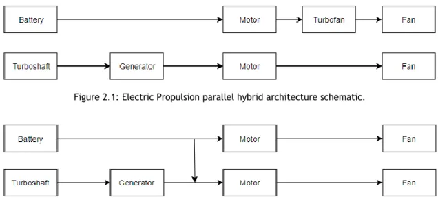
Hybrid-electric architectures either augment a traditional turbo-fan with an electric motor in parallel hybrid configuration, or use a turbo-shaft and generators bolstered by a battery to feed a set of EM-driven fans in a series configuration [8-9]. Both types continue to employ a turbo-fan for large parts of the flight envelope due to the current shortcomings of battery capacity and, draw on electrical power either in high thrust parts of the flight envelope such as take-off
7 and climb, or switch entirely to battery power during cruise, when thrust requirements are low. Figure 2.1 and 2.2, show a schematic of this architecture type, for parallel hybrid and series hybrid, respectively.
Figure 2.1: Electric Propulsion parallel hybrid architecture schematic.
Figure 2.2: Electric Propulsion series hybrid architecture schematic.
A second configuration is a turbo-electric architecture, where kinetic energy from a turbo-shaft is transformed via a generator into electrical energy to drive one or multiple distributed electric motor driven fans. This configuration gives the airplane designer complete freedom over the number and location of the propulsive fans, potentially leading to more efficient designs with higher propulsive efficiency [10-13]. A schematic of this type of architecture is presented in figure 2.3.
Figure 2.3: Electric Propulsion turbo-electric architecture schematic.
The third and final option is all-electric propulsion, where the sole source of supply is a battery and the gas turbine and associated fuel system present in the hybrid-electric architecture type and turbo-electric configurations are completely eliminated. As it has been emphasized, the range of an airplane with an all-electric propulsion system will heavily depend on the battery storage capacity and weight [14-16]. As before, next follows a representation of the all-electric architecture type schematic, figure 2.4.
8
2.2 Current Electrically-Propelled Airplane Landscape
It has been clear that, for the past decades, investors and engineers are aligned in the potential of EP and teams around the world are already making strides towards further electrification. There has been a significant increase in development of EP driven airplane programs, ranging from incumbent aerospace giants to new start-ups, which are making the industry bustling with activity.
These new programs can be categorized into 4 main focus points: General Aviation (GA), Urban Air Taxis (UAT), Regional Airplanes (RA) and Large Commercial Airplanes (LCA). Around half of all new programs have been launched by start-ups and, 5% of these are being backed by major non- aerospace companies. Only 20% of these programs are being launched by major airframe Original Equipment Manufacturers (OEM), such as Boeing [17], Cessna and Agusta Westland. Most of the developments in this category are being conducted by Airbus in conjunction with Rolls-Royce and NASA [6-7].
Most of these developments are split roughly equally between North America and Europe, reflecting the location of current production of most of the world’s airplanes. A considerable amount of these projects, almost half of them, are only focusing on single fan designs, with a third aiming to capture the propulsive efficiency benefits of EP through distributed fans [18-21]. It should be pointed out that much of these programs being developed are only expected to have major breakthroughs in the upcoming decades, as other systems technologies also need to progress much further.
The segment of GA has been a hotbed of development activity. The uptake in this segment has been enabled by existing airplane architectures already using propellers for propulsion either allowing a simple substitution of the powerplant or allowing designers of new platforms to draw on a plethora of relevant past data. GA incumbents have been releasing retrofitted versions of already existing airplanes, such as the electric Cessna 172 and Pipistrel’s Taurus Electro or WATTsUP electric trainer. Small start-ups have also jumped in and proven their value with the development of programs such as the DigiSky with the SkySpark demonstrator. This class of airplane has proven to be an effective segment as a test bed for further development of EP airplanes and, as a result will be the main focal point of this dissertation.
There has been clear acceleration in the launch of development projects for 1-4 passenger UAT. Typical developments in this area are currently targeting a limited range of up to 50 km, with vertical take-off and landing (VTOL) and all-electrical propulsion to give the benefits of low noise pollution and zero emissions.
Many of these developments have advanced and made ground-breaking progress. In Germany, the VoloCopter VC-200 flew as early as 2013 [22]. Since the fourth quarter of 2017, VoloCopter has been authorized as an Autonomous Air Taxi in Dubai, having received clearance from the
9 United Arab Emirates' Roads and Transport Authority. Lilium Aviation also performed its maiden flight in 2016 and plans a 5-seater taxi for urban mobility, and the Chinese drone company Ehang has also been cleared as of last year to start testing its Ehang 184 in Nevada [23], beginning its FAA regulatory approval process.
A number of other organizations and companies are operating in stealth mode without much press release, but have also made noteworthy progress. Zee Aero's full-scale prototype was recently spotted in flight, while Joby Aviation's S2 was expected to start full-scale prototype testing earlier this year. Other projects like the DeLorean Aerospace's DR-7 continue to make progress with a VTOL flying car, due for its first flight in late 2018.
A further development in these urban mobility concepts actually came from automotive companies like Geely and mobility providers like Uber. The former has entered the aerospace industry by acquiring US-based Terrafugia, with its TF-X flying car concept. The latter provided a detailed business case in its "Elevate" white paper published in October 2016 [24], which in turn motivated additional organizations like Bell Helicopter, Mooney Aircraft and Pipistrel to partner with Uber to work on an undisclosed project. While this may just be an early spike of activity before the pace of development settles down, there certainly seems to be a willingness from corporates and investors alike to enter this field.
Aerospace incumbents, not to be undone, are also investing considerable resources into the trend. However, industry giants Airbus and Boeing are taking different approaches. Airbus has taken an holistic approach with an Urban Air Mobility portfolio, not only initiating projects within existing divisions such as Airbus Helicopter and the CityAirbus [25], a four-seater all-electric multi-rotor VTOL airplane for urban environments, but also identifying a need for increase in development with the creation of a dedicated new organization named A3, a Silicon Valley-based outpost tasked with overseeing the development of Vahana, a single-seat autonomous electrically-propelled airplane which was expected to carry out its first full-scale demonstration flight by the end of 2017 [26]. Concurrently, Airbus remains on the lookout for potential investments in start-ups through Airbus Ventures. Boeing, on the other hand, has chosen a largely opportunistic approach by dedicating its venture capital arm HorizonX to finding promising start-ups to invest in, often along with partners, including the Zunum RA program.
In the next size category are the RA with ranges between 500-1,000 km that are targeting both commercial inter-city transport and GA use by corporations and high net worth individuals. Developers in this segment are evaluating both hybrid and all-electrical propulsion and have a business case related not only to the replacement of current non-electric airplanes, but also to competing with road or rail-based transportation, drawing on the benefits of EP in terms of reduced noise and zero emissions.
10
New ventures launched in this segment include Eviation's Alice project, a nine passenger all-electric commuter and business airplane planned to first fly in late 2018, whilst others appear a little further behind in development such as XTI Aviation's TriFan 600, a six-seat hybrid-electric VTOL business airplane and an initial product from Zunum Aero, which is developing commercial aviation platforms of three different sizes, with the smallest and first-to-market variant being a 10-seater RA.
RA are also being considered by some companies as test beds, subsequently to be scaled up to larger platforms. Existing aerospace and aviation companies are thus also active in this segment. Boeing, for example, has recently partnered with JetBlue to co-invest in the aforementioned Zunum Aero, which plans to eventually scale up its regional development to a 50-seater platform.
The well-documented barriers to entry in the LCA segment mean that most of the development activity in electrically-propelled LCA has been focused on by the incumbents, mainly Airbus and Boeing.
Airbus has already gone so far as to release a roadmap to the first electric LCA, though without a predicted entry into service date, in pursuit of the company's long-term goal of developing a single aisle airplane with a hybrid-electric configuration. The size of the, airplane would require around 40 MW of power for take-off and 20 MW for cruise, in support of which Airbus is developing a demonstrator airplane called the E-Fan X in the 2 MW class that is scheduled to fly within the next 2 years [6-7]. In parallel, Boeing has also released a roadmap to an electrically-propelled airplane for around 2030, building on the achievements of the more Electric 787 and demonstrating the way in which the more electric airplane technology described earlier is complementary to and paving the way towards EP.
In a challenge to the incumbents, Wright Electric, a new start-up staffed by a team previously funded by NASA, has established a goal that all short-haul flights should be electrically-powered within the next 20 years. In support of this goal, Wright Electric has announced its intention to build a 150-seat electrically-propelled airplane within a decade to compete with the smaller members of the A320 Airbus and 737 Boeing families [27]. The company is taking an oppor-tunistic approach to exactly which technologies should be implemented, indicating that if, should battery technology advance with sufficient speed then the airplane will feature an all-electric concept, while if progress on batteries becomes stale, then a hybrid-all-electric approach will be adopted instead. These technical barriers to EP will be explored with more detail in the next section.
2.3 The Barriers to Electrical Propulsion
Despite the clear enthusiasm that electrically-propelled airplanes have demonstrated by the plethora of new development programs launched, a significant number of barriers remain,
11 spanning market demand, technology, and regulation. In this section some of the barriers that EP will need to overcome, are described.
2.3.1 Market Demand
The first and foremost barrier for applications such as UAT is that of demonstrating whether there is market demand at a price that generates an acceptable return on investment to cover development and operating costs. In many ways the arguments in favor of UAT are reminiscent of those put forward in favor of air taxi companies operating Very Light Jets. Furthermore, UAT programs will need to break the traditional aerospace cycle of development cost over-runs and schedule delays, but perhaps this is just where the injection of outside experience and flexibility will overcome the traditional aerospace operating method.
Similar challenges will also exist in the RA segment. Although the 40-50 seat RA market was holding in the late 1990s and early 2000s, recently airlines have switched to buying larger RA in the 70-90 seat category owing to the high per-seat cost of smaller airplanes. As many of the initial sets of electrically-propelled RA appear to be targeting the declining smaller end of the RA market, the manufacturers will have to convince the airlines of the valuable proposition these new products will offer. Furthermore, regional jets typically fly 6-8 sectors per day, so any all-electric RA will need to either have a very rapid re-charging capability, or the ability to exchange depleted batteries for freshly-charged batteries within the time of the airplane’s turnaround at the gate. This leads to the second barrier to EP, the current battery technology employed.
2.3.2 Battery Performance
A battery is an electrochemical device that converts stored chemical energy into electrical power. In half of the cell, positively charged ions, called cations, migrate to a cathode electrode through an electrolyte. In the other half of the cell, negatively charged ions, called anions, migrate to the anode electrode through an electrolyte, as shown in figure 2.5. An electrical load can be placed between the battery leads. Batteries operate with a closed thermodynamic cycle.
High battery storage capacity and low weight are clearly crucial to all-electric and hybrid-electric architectures and, in order to allow the creation of products with commercially viable payload-range characteristics. It is generally acknowledged that electrical storage systems used for all-electric airplanes, need high specific energy values, to become cost-effective and efficient, considering a bare minimum of 500 Wh/kg as a good starting value.
12
Figure 2.5: Battery cell process of operation [28].
The problem is, in the current spectrum of today’s battery technology, commercial batteries offer a range of values from 150-250 Wh/kg. This does not mean that, there are no batteries currently that can provide higher values of specific energy than the ones mentioned before. As a matter of fact, currently the highest demonstrated value of specific energy reported till this day ranges from 500-700 Wh/kg. The problem is that, these batteries employ technologies, more specifically electro-chemistries, that have been reported as possibly very toxic and corrosive and, even susceptible to detonation if not handled properly, such is the case of Boeing 787 Dreamliner lithium ion battery incidents of 2013. Due to this, most of the batteries have seen very small utilization, currently in private and military sectors and almost none for the commercial sector, due to its safety risks [29].
There is one promising technology in development, that if it were to prove to be successful, it could revolutionize the EP industry, and enable a giant leap in its development. This is referring to the Lithium-air batteries. At present, two types of reversible lithium-air batteries have been proposed [30], namely non-aqueous and aqueous systems. The former, reports to be able to produce up to 3.460 kWh/kg from the reaction:
2𝐿𝑖 + 𝑂
2=
𝐿𝑖
2𝑂
2 (2.1)And an open cell voltage (OCV) of 2.96V demonstrated in for the discharge state. For the charged state, oxygen is excluded and the specific energy density is reported to be able to reach values of approximately 11.7 kWh/kg, which comes just short of the energy density provided by gasoline of around 13 kWh/kg at its purest form. The latter calculates its specific energy density from the reaction:
4𝐿𝑖 + 6𝐻
2𝑂 + 𝑂
2= 4(𝐿𝑖𝑂𝐻
.𝐻
2
𝑂) (2.2)
But due to its active electro-chemistry reactions and, formation of unwanted concentrations and saturation of some of its products, the specific energy density resultant from the reaction, for the discharged state with and OCV of 3.0V, is about 2.004 kWh/kg, and 1.910 kWh/kg for
13 the charged state. Until recently, no technical basis existed, to support these estimated values obtained by their reaction’s calculation. This was due to the challenges found in developing cathode materials and electrolyte systems for these batteries. References [31-34] give an insight to what these challenges are.
However, with the advancements of nanotechnology for the past years, this has enabled some progresses in achieving a possible solution for its current challenges. Several authors [35-36] have proposed one of the possible solutions, by developing a high density, graphene-based porous structure used as the cathode for LiO2 batteries. This solution has proved to be a major breakthrough in the development of these batteries and possibly serving as a test bed for future developments. The following years will prove to be instrumental for the maturation of this technology and development of the first possible battery capable of standing toe-to-toe with fossil fuels.
Focusing now on more immediate and existing battery technology, a brief description will be made on the current lithium-ion batteries, which have proven to be the current leading battery technology for most applications in day-to-day life.
Lithium-based battery systems are characterized by high energy density levels, relatively high voltages, and low weight-to-volume ratio but, in general, tend to be more expensive than equivalent battery technologies with aqueous electrolytes, such as alkali disposable batteries and zinc/air batteries in the primary battery sector, and nickel metal hydride, nickel cadmium and lead batteries in the secondary battery sector [37].
Primary lithium batteries have existed since the 1970s, are easy to use and provide convenient sources of energy for portable applications. The batteries usually require no or very little maintenance and have a long shelf life; modern lithium batteries can usually be stored for up to 10 years, and there are special batteries with solid state electrolyte that can be stored for more than 20 years. The storage tolerance at elevated temperatures is generally good, in some cases up to 70°C. There are 3 classes of primary lithium batteries, firstly solid-state batteries, which are characterized by low power but superior shelf live. The term solid-state is used because the electrolyte is solid and the ion transmission between the electrodes takes place in a solid, non-electrically conductive material, usually a polymer. Secondly, batteries with a solid cathode are usually found in coin cells or small cylindrical batteries. Thirdly, batteries with soluble cathodes, which are usually found in industrial and military applications, manufactured in large cell sizes, up to 35-40 Ah, but also available in smaller sizes. All of these batteries have lithium anodes. The cathode material determines the battery system.
Over the last few years the market has seen the introduction of battery types in which the cathode consists of a mixture of different electrode materials. The purpose of these batteries is to provide a system that can accommodate both high and low loads.
14
There are two main groups of rechargeable lithium batteries, one of which uses lithium metal as the negative electrode. These are called lithium metal batteries. Lithium metal batteries were launched on a limited scale for consumer electronic products in the 1980s, but were withdrawn quickly because of safety problems with the lithium electrode. Lithium reacts with the electrolyte, forming dendrites on the surface of the electrode. Under repeated charging, the surface of the anode increases, with a corresponding increase in its reactivity and thermal sensitivity. More recently, however, the lithium metal anodes have once again found practical application in research, although they have not yet been marketed on a large scale. One way of reducing the fire risk in lithium metal batteries is to replace the electrolyte with a solid-state polymer electrolyte, that does not react with lithium.
The second type of rechargeable lithium battery is called a lithium ion battery, which has a negative terminal that consists of a carbon-based material, usually graphite, or another type of alloy or material that permits storage, of lithium in the structure. This category includes lithium polymer batteries, which differ from traditional lithium ion batteries in that they have an electrolyte that is bound within a nonconducting polymer matrix. Lithium ion batteries were introduced by SONY in 1991. This type of battery is constantly gaining new ground, and the areas of use are constantly expanding, and lithium ion batteries are currently used in all sorts of portable applications within consumer electronics, medical technology and military systems. The general properties that contribute to this are the high energy density of the lithium ion battery and its specific energy, compared with other rechargeable types of battery. Its other properties include low self-discharge and, relatively long recharge lifetimes. High costs and the safety aspects are its main barriers, as well as the fact that access to large cell types, battery cells with a capacity exceeding 5 Ah, is limited. Existing lithium ion batteries also suffer from functional limitations at low temperatures. Tables 2.1 and 2.2 give an overview of the main primary and secondary lithium battery types and its main properties, respectively.
Further analysis suggests that the current trajectory of Lithium-ion battery development will bring gravimetric density to about 400-450 Wh/kg by the mid-2020s [38]. However, further development or new battery chemistries will need to reach the 500 Wh/kg mark, and even if batteries were to reach this level, the energy storage density will still be a factor of 25 lower than the approximately 12 kWh/kg delivered by jet fuel. In addition to high energy density, high re-charging speeds and long battery life-cycles will be crucial to underpinning the economics of battery-powered airplanes. Therefore lithium-air batteries are seen as the ultimate goal for research and development for all-electric flight, as they are currently the only type of batteries that theoretically can go toe-to-toe with its fossil fuel counterpart.
15 Table 2.1: Primary lithium battery specifications [39].
System Rated Voltage [V] Specific Energy [Wh/kg] Energy Density [Wh/l]
Class 1: Solid-State System
Lil2 2.8 220 - 280 820 - 1030
Class 2: Batteries with Solid Cathodes
Li(CF)n 3.0 220 - 590 550 - 1050
LiFeS2 1.5 260 500
LiMnO2 3.0 230 - 270 535 - 620
LiAgV4O11 3.2 270 780
Class 3: Batteries with Soluble Cathodes
LiSO2 3.0 260 415
LiSOCl2 3.6 275 - 590 630 - 1100
LiSO2Cl2 3.95 450 900
Table 2.2: Secondary lithium battery specifications [39]. Cathode
Material Rated Voltage [V] Specific Energy [Wh/kg]
LiCoO2 3.6 110 - 190
LiMn2O4 3.7 – 3.8 110 - 120
NCM 3.7 95 - 130
NCA 3.7 --
LiFePO4 3.2 – 3.3 95 - 140
Still, as mentioned before, currently these batteries present even more barriers and constraints to its development, one of which is its relative lower energy density capabilities compared with the other existing lithium batteries, as well as being very unstable due to excessive expansions of the battery derived by its electro-chemical reactions. This leads to one of the other main barriers to EP which is, battery safety/hazard containment. With many past events of lithium ion battery incidents that can be read from [29] in mind, electrically-propelled airplane developers will need to develop effective hazard containment systems for batteries, not only to meet airworthiness requirements, but also to satisfy public safety concerns. Whilst hazard containment systems for batteries are arguably less challenging than for volatile aviation fuel, the need for such systems are often overlooked in the race for higher energy densities. Batteries are not the only method of storing energy through electrical means, fuel cells also deserve its recognition as a possible storage device for an all-electrical airplane. The next section is devoted to this system, a brief explanation of its process will be given, as well as, the advantages and disadvantages when compared with batteries.
16
2.3.3 Fuel Cells Performance
Fuel cells are electrochemical devices that use chemical reactions of a fuel source and oxidizer to generate electrical power. The fuel and oxidizer are consumed in the conversion process and, the byproducts are either exhausted from the fuel cell or stored onboard the airplane. The reaction between the fuel and oxidizer occurs in the presence of an electrolyte which is not consumed. Fuel cells have an open thermodynamic cycle.
Hydrogen-powered fuel cells operate in a similar manner regardless of type, figure 2.6 exemplifies this. A catalyst converts hydrogen into a positively charged hydrogen ion and a negatively charged electron at the anode. The hydrogen ions freely pass through the electrolyte, but the electrons are blocked.
Figure 2.6: Fuel cell process of operation [28].
This creates a voltage potential difference between the anode and cathode. The electrons are directed via porous gas electrodes embedded in the cathode and anode. The hydrogen ions combine with oxygen, and the electrons returning from the electrical load to form water, which can be either liquid water or water vapor.
Because water vapor is the only emission, fuel cells are widely considered to be a clean power source. Multiple individual fuel cells can be combined in a fuel-cell stack. Like batteries, the fuel cells can be arranged in series or parallel to produce the desired voltage or peak current. The voltage per cell is defined by the fuel cell type, and the peak current is a function of the active surface area. The two most common types of fuel cell are proton exchange membrane (PEM) and solid-oxide fuel-cell (SOFC) types.
PEM and some SOFCs react with hydrogen and oxygen to generate electricity and water. The equivalent Brake Specific Fuel Consumption (BSFC) for a PEM fuel cell can be approximately 91.24–152.07 g/kWh, where the reference fuel is hydrogen. The temperature of the PEM fuel cell must be controlled to prevent thermal loading failure. The chemical reaction is exothermic, so that the heat generated must be rejected to keep the system within the operating limits.
17 The electrolyte membrane must generally be kept low to prevent damage, which requires rejection of low-grade heat.
The membrane must be properly hydrated to ensure that water is created and evaporated at the same rate. If the required hydration is not maintained, the membrane will dry and crack, allowing the hydrogen and oxygen to react directly and generate destructive heating. On the other hydration extreme, excessive water will flood the electrodes and block the reaction. PEM fuel cell systems involve numerous support systems to ensure effective operations. Actively controlled pumps must properly hydrate the membrane. Thermal management might require heat exchangers. The incoming air might require conditioning, including dehumidification and pressurization.
SOFC are high-temperature fuel cells that have the potential to run on numerous fuel types in addition to hydrogen. SOFC are not as mature as PEM because of challenges with high-temperature materials. However, SOFC offer the potential for greater efficiency. An airbreathing fuel-cell system must intake air for the oxygen required for operation. High altitude operation might require one or more turbos to provide air at the appropriate pressure, much like a reciprocating engine. A combustor separate from the fuel cell burns hydrogen gas and conditioned oxygen to drive the turbo expander, which, in turn, drives the compressor. Fuel-cell systems can operate in a regenerative fashion. The byproduct of hydrogen-oxygen fuel cell operation is water, which can be captured and stored. Power is provided to an electrolyzer by a separate power source, such as solar arrays, to separate water into hydrogen and oxygen in a reverse osmosis process. The hydrogen and oxygen are generally stored in gaseous form to avoid the losses associated with cryogenic storage. Fuel cells that perform the function of an electrolyzer when operating in reverse are known as regenerative fuel cells (RFC). RFC are generally not as efficient as optimized electrolyzer systems, but they can provide weight savings and complexity reductions by combining both functions into a single element.
One of the biggest advantages of fuel cells relative to batteries is the hydrogen’s very high specific energy value of 33.3 kWh/kg, which even stands out from the gasoline’s value of approximately 13.0 kWh/kg. However, hydrogen is notorious for being explosive. Public perceptions are driven to a large extent by the famous Hindenburg airship accident, which was primarily caused by the flammable skins rather than the hydrogen lifting gas. Still, many of these concerns might be unfounded. Hydrogen is the lightest gas and tends to diffuse quickly upon interaction with the atmosphere. Hydrogen can be stored and handled safely with proper equipment and procedures. The main methods of hydrogen storage are pressurized hydrogen gas, cryogenically cooled liquid hydrogen, and chemical storage.
18
Unlike conventional batteries, the reactants are external, meaning that as long as the reactants continue to be fed to the fuel cell, electricity can be produced. Moreover, refueling an empty reactant tank is also much faster than recharging a battery.
There are other types of fuel cells currently in existence, including alkaline fuel cells (AFC), direct methanol fuel cells (DMFC), phosphoric acid fuel cells (PAFC) and molten carbonate fuel cells (MCFC). However, PEM fuel cells are seen as the most viable for vehicular applications due to many of its characteristics such as the electrolyte being solid, and so leaking of corrosive fluids is not an issue and the fuel cell can operate in any orientation, the operating temperature being relatively low (80-100°C) meaning start-up times are short, the relatively high power density compared to the other fuel cell types and, finally the possibility of using air to supply the required oxygen through an airbreathing system.
One of the main drawbacks of a battery powered airplane (BPA) is that the limited energy capacity of batteries means that the airplane range is significantly less than that of a conventional airplane. With the ability to carry more energy on-board the airplane, the advantages of a fuel cell powered airplane (FCPA) start to become apparent. The FCPA can achieve a much longer range with an on-board hydrogen gas tank, making the FCPA range competitive with conventional and hybrid airplanes. Although at a first glance, fuel cells look like a more prominent solution for future electrification of airplanes, the reality is that batteries continue to be perceived by most as the prominent solution for the realization of the all-electric airplane dilemma [40].
The efficiency of a BPA is unsurpassed and it will always take more energy to get from point A to point B in an FCPA. The higher efficiency is due to the electrochemical reaction in batteries being more efficient than the reaction in a PEM fuel cell but also because the latter requires a balance of plant system that delivers the external reactants to the reaction sites. The efficiency of the PEM fuel cells is increased dramatically with higher reactant pressure, and the air compressor consumes the most energy of the balance of plant components, thereby reducing the efficiency the most. The BPA also relies on simpler technology that does not cost as much to build. While BPA have range and recharging limitations, FCPA boast an efficiency that is higher than ICE airplanes but do not offer a large enough gain to overcome the higher purchase price and lack of hydrogen refueling infrastructure that currently exists [40].
2.3.4 Solar Power Performance
Solar powered airplanes have also been at the forefront of EP research and development and, to this day have already accomplished considerable milestones in this area, such as the Solar Impulse II, which completed the first flight around the world, taking over 505 days to fly 42000 km at an average speed of 72.4 km/h, being only powered by solar energy through more than 17000 solar cells [41].
19 Solar cells use the photovoltaic effect to convert the sun’s radiated power into electrical power. This power does not require onboard energy storage for peak daylight operations. However, multiday flights require that excess energy be stored to power the airplane through the night. An airplane that solves this energy balance can operate almost indefinitely, bounded only by reliability and component life, as was shown with the Solar Impulse II program. Individual solar cells are combined in solar arrays. Much like a battery and fuel cells, the solar cells can be arranged in combinations of series and parallel to yield the appropriate voltage. Integrating solar arrays on an airplane involves compromises across a number of disciplines. A flat array panel can be mounted on the aft upper surface of the wing, perhaps between the maximum thickness point and the trailing edge. This is the region of the airfoil with the least curvature on the upper surface. An externally mounted array requires a large flat section over this region, which increases the airfoil drag and can reduce the maximum lift coefficient. Even arrays made of brittle crystalline cells can accommodate some curvature, and so very large solar-powered airplanes can have externally mounted arrays on relatively conventional airfoils [28].
Alternatively, the array can be mounted inside a wing, though this requires a covering material that does not absorb light in the critical wavelength range for the solar cell. Also, any structure required to maintain the wing aerodynamic geometry, such as ribs and spars, can cast a shadow on the array. Solar arrays cause structural challenges. Solar-powered airplanes usually have gossamer structures, and the solar arrays comprise a large portion of the wing weight. Most of the solar-array weight is aft of the wing torsional axis, which can require additional structure or active aeroelastic control along the wing to prevent flutter. The weight of the arrays can create static sink on the wings both along the span and torsionally [28].
Solar arrays drive wing sizing. Many solar-powered airplane design efforts find that the wing area required to generate propulsion power is greater than the optimum wing area for minimum power flight. The wing must grow to accommodate the additional solar collection area. However, the increased area results in higher airplane weight, more drag, and hence more required power. The wing sizing is often solved through optimization. Other surfaces such as horizontal tails may grow in size to increase the collection area. Solar arrays perform best when oriented normal to the sun vector. Aerodynamic surfaces such as wings and horizontal stabilizers perform best when nearly horizontal. The stressing conditions for solar-powered flight involve low sun angles, which coincide with early morning, late afternoon, winter, and extreme latitude flight. To collect at these low sun angles, the aerodynamic surfaces must be made more vertical to increase the normal component of the sun vector [28].
Some approaches include the Aurora Flight Sciences Vulture Z-wing, vertically folding wing tips, and rolling vertical tails. All of these configurations increase the power required for flight, but
20
more than compensate for this by increasing the power generated by the arrays. These configurations convert to a minimum drag state to reduce the power required to fly at night. As can be observed solar power yields feasible results but at the cost of restrains that make this kind of technology impossible to be implemented for the all-electric airplane capable of standing its ground to ICE models performances. This type of technology would be more suitable for long sustained missions such as unmanned reconnaissance airplanes and, aerospace programs such as satellites.
2.3.5 High Power Density Generators and Motors
Hybrid-electric, turbo-electric and all-electric airplanes will all require light, efficient and high-power density motors to fit in with the weight and size constraints of an airplane, particularly for configurations that employ multiple distributed fans to achieve high propulsive efficiency. Hybrid-electric and turbo-electric architectures will also require light, efficient and high-power density generators to convert shaft power to electricity, along with an intermediate, lightweight gearbox to reduce the turbine's high rotational speed to a slower rate suitable for a generator.
Fortunately motor and generator development has been far more successful in the immediate time compared with battery technology and, as of today there is a plethora of light, efficient high-powered EM, capable of providing up to 300 kW, with power-densities of about 9.0 kW/kg and efficiencies of 95%.
In addition to generating quantities of power an order of magnitude larger than current airplane, electrically-propelled airplanes will need the power electronics to convert, switch and condition this power. As well as performing these functions with minimum electrical loss, the requisite power electronics will also need to operate with the minimum associated heat generation. This factor is particularly important given the multi-MW electrical power systems that will be required for RA and LCA and the resulting need to dump any surplus of heat gen-erated. Conventional airplanes can currently use fuel as a reservoir to dump surplus heat, but this option will not be available in electrically-propelled airplanes.
Also, transmitting large quantities of electrical power around an airplane should ideally be done at high voltages in order to minimize resistive losses, however transmitting high power at high voltage will inevitably lead to the risk of insulation breakdown and arcing given the limitations imposed by Paschen’s Law. At the same time, long cable runs in configurations employing multiple propulsive fans distributed around the airplane will add further weight, compounding the additional weight already required for on-board batteries.
2.3.6 New Airplane Architecture
As was mentioned before, the conventional structural configuration, is not the best suitable design type to model electrically-propelled airplanes, as these can benefit greatly from certain
21 aspects that conventional airplane designs just cannot offer, such as more aerodynamic configurations.
One of the potential improvements offered by EP is the benefit of boundary layer ingestion [42]. Many of the RA and LCA electric architectures propose the use of aft-mounted propulsion systems, positioned such that air coming off the airplane fuselage is ingested into the propulsion system. Despite the relatively slower speed of the ingested air, electric fans would suffer from less efficiency loss in the more disturbed air compared to the fan of a conventional turbofan, whilst also benefitting from fewer installation constraints.
Designers have also been pushing for a more distributed propulsion system configuration, as it offers a wide array of benefits to electrically-propelled airplanes, but at the moment, also offer a significant amount of challenges that need to be resolved in order to make this idea a key feature of future EP concepts. Del Rosario et al offer some clarity and insight on this subject.
2.3.7 Regulation
To enable the potential of EP aviation, there will need to be effective new regulations for new technologies, new platforms and new aviation systems.
First, as new technologies are developed in the field of electric aviation, each technology will need to have regulatory backing to be applied. For example, regulation will play a part in verifying and certifying the use of MEA systems, and any progression with EP will require airworthiness certification, as well as broad regulatory acceptance for enabling technologies such as high-powered batteries, high voltage distribution, and boundary layer ingestion. Second, regulation will be critical to enable new platforms. Regulation and certification procedures for new architectures such as distributed fans will be required to allow the full potential of EP to be achieved.
Third, if and when technologies and platforms progress to enable UAT, far-reaching regulatory changes would be required to enable entirely new aviation systems, such as for the regulation and control of urban commuter air transportation systems, as well as integration with other urban infrastructure and corresponding regulatory regimes.
At the heart of regulation are the issues of safety and reliability. In an age of increasingly significant cyber-security concerns, the introduction of autonomous flight systems and the potential of urban commuter air transport become even more challenging with the possibility of vulnerable software and systems. Engineers, investors and regulators alike must address two main safety issues. First, air traffic control infrastructure and airspace management will become of paramount importance, necessitating the management of an increasing number of UAVs and the management of potential urban commuter air transports, requiring control of an
22
entirely new airspace, coupled with integration into existing air traffic control systems. Second, governments, regulators and private companies alike will have to invest in measures to prevent cyber-security breaches in increasingly software-driven airplane, for all platform types. In recent months, both the FAA and EASA have taken meaningful steps to open the doors to EP. A key change is in FAA Part 23 and EASA CS23. Since 2017, larger classes of GA airplanes are able to fly non-traditional engine types legally, including EM. This not only opens revenue potential for developers in general aviation, but this category of platform is a key stepping stone to even larger architectures. There is, however, a long journey ahead and regulation must keep pace with technological evolution for electrically-propelled airplanes to achieve their potential.
![Figure 1.1: Total World CO 2 emissions from fuel combustion from 1971 to 2015 [1].](https://thumb-eu.123doks.com/thumbv2/123dok_br/19168564.940274/23.892.202.734.728.978/figure-total-world-emissions-fuel-combustion.webp)
![Figure 1.2: Trend in emissions of air pollutants from transports [2].](https://thumb-eu.123doks.com/thumbv2/123dok_br/19168564.940274/24.892.152.646.102.560/figure-trend-emissions-air-pollutants-transports.webp)
![Figure 2.5: Battery cell process of operation [28].](https://thumb-eu.123doks.com/thumbv2/123dok_br/19168564.940274/34.892.215.636.108.312/figure-battery-cell-process-of-operation.webp)
![Table 2.2: Secondary lithium battery specifications [39].](https://thumb-eu.123doks.com/thumbv2/123dok_br/19168564.940274/37.892.156.773.120.679/table-secondary-lithium-battery-specifications.webp)
![Figure 2.6: Fuel cell process of operation [28].](https://thumb-eu.123doks.com/thumbv2/123dok_br/19168564.940274/38.892.294.554.417.620/figure-fuel-cell-process-operation.webp)