ISSN 1549-3636
© 2011 Science Publications
Corresponding Author: V. Geetha, Department of Electrical Engineering, Government College of Technology, Coimbatore, 641 013 Tamil Nadu, India Tel: 9245158225
744
OR-Bridging Fault Identification and Diagnosis for Exclusive-OR
Sum of Products Reed-Muller Canonical Circuits
V. Geetha, N. Devarajan and P.N. Neelakantan Department of Electrical Engineering,
Government College of Technology, Coimbatore, 641 013, India
Abstract: Problem statement: The faults in digital circuit can be classified broadly as single stuck-at-faults, multiple stuck-ay-stuck-at-faults, stuck-open stuck-at-faults, stuck-on stuck-at-faults, path delay stuck-at-faults, transient faults. Extensive research had been carried out in the field of testing of digital circuits to limit the number of input vectors. The cardinality of the test vectors proposed by many authors was quite high for large number of input variables. In this study a testable circuit with a small test set for detection and diagnosis of OR-bridging type fault in Reed-Muller canonical Exclusive-OR Sum of Products logic circuits, independent of the function for a given number of inputs had been proposed. Approach: A network structure comprising a set of Exclusive-OR gates and gates and a couple of auxiliary outputs were considered. The circuit as well as the test vectors were simulated by MATLAB coding. The fault-free and OR-bridging faults involving any two lines of control and data lines were then simulated. The outputs were represented in a compact decimal form for ease of tabulation. Two quantitative indices for comparison of results had also been discussed. Simulation and analysis for various random functions had been presented. Results: From the test results it was found that the identifiability for the set of random functions tested was more than 90% with just n + 5 test vectors compared to 2n test vectors required for conventional testing. It was also observed that even though the overall distinguishabililty factor was in the range of 45-80%, the individual set distinguishability was more than 90%. Conclusion: The proposed scheme had reduced the possibility of unidentifiable faults for the specified type of function. The location was also diagnosed through the output set. The analysis and diagnosis had been done through compact tabulation and two quantification indices.
Key words: Reed-Muller Canonical (RMC), Exclusive-OR Sum of Product (ESOP), Testable realization, OR-bridging fault, distinguishability factor, XOR gate, data inputs, logic functions, test vectors
INTRODUCTION
Any arbitrary logic function, in general, can be expressed in Reed-Muller Canonical (RMC) form as:
F = (a0 ⊕ a1x1* ⊕ a2 x2* ⊕…⊕ an xn* ⊕ an+1 x1* x2*
⊕…⊕ am x1* x2*…xn*)
where, xn* can be xn or its complement, an is either 0 or
1 and m = 2n-1. However, there can be variations in such form. Of these, the Exclusive-OR Sum-of-Products (ESOP) form with the least number of product terms and hence needing least number of AND gates, is very much suitable for hardware implementation.
Single non feedback OR Bridging faults involving two lines at a time of the control and data inputs only are considered. Zhongliang (2002) demonstrated that
single stuck-at fault detection can be achieved with only n +5 test vectors. In this study, it is shown that bridging fault detection and diagnosis can also be achieved with the same n+5 test vectors through MATLAB simulations for a few specific functions. Two quantitative indices, called identifiability factor and distiguishability factor are considered for comparison of the testability nature of given circuits. The identifiability factor is defined as the ratio of the number of faults correctly identified by the test set to the total number of possible faults of the type considered. The existence of faults can be recognized from the set of outputs measured which will be different from the fault-free circuit.
745 non-faulty case. The existence of even a large percentage of indistinguishability may not mean the circuit is not reliable, since it is still possible to identify the faulty condition of the circuit and take appropriate remedial action. The set of binary values for an output is converted into its decimal equivalent for convenience in comparison and ease of tabulation.
Literature survey: A classical method of generating test patterns for very large and complex logic functions is Linear Feedback Shift Register (LFSR) based pseudo-exhaustive or pseudo-random type Kalay et al. (2000). However, this does not work well with ESOP form as shown by Drechshler et al. (1997). A Positive Polarity Reed-Muller network for detection of stuck-at faults with a universal test of size n+4, n being the number of data inputs, was proposed by Reddy (1972). Though quite good for self-testing, the method is economical only for the specified form, which obviously has more number of product terms than the other forms in most cases. Multiple stuck-at fault detection for ESOP circuits was carried out by Pradhan (1978). However since the cardinality is 2n+6+ ∑nCe, e
= 0 to j, the order of ESOP expression, the test set is not universal and also is too large to be practical for large input functions.
Stuck-at and bridging faults with a universal test set for Positive Polarity Reed-Muller network has also been reported Bhattacharya et al. (1985). Multiple fault detecting GRM realizations was propounded by Sasao (1997). It was shown that 2n+s+3 test vectors, where s is the number of product terms in the logic function are required for single stuck-at fault detections in Generalized Reed-Muller/ESOP circuits while 2n+s vectors are required for detection of and/or bridging faults in such circuits Zhongliang (2003). Here too, the test set is not universal as it depends on s, the number of product terms of the function. Kalay et al. (2000) described an ESOP implementation with a universal test set of size n+6 for single faults. A robust and universal sequence has been proposed for stuck-open type of faults in GRM/ESOP cmos implementations Rahaman et al., (2004). Zhongliang (2002) demonstrated that the single stuck-at fault detection can be achieved with only n+5 test vectors. Two methods, each with a small modification in this scheme in ESOP RMC circuits had been proposed by Neelakantan and Jeyakumar (2006a) for analysis and diagnosis of single stuck-at faults. This study is an extension of the work done by Neelakantan and Jeyakumar (2006b) for the analysis and diagnosis of OR-bridging faults in any of the pairs of data and control lines of the ESOP RMC circuits.
MATERIALS AND METHODS
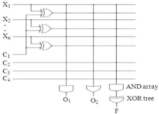
Network structure: The network structure of the scheme is the same as that proposed by Zhongliang (2002) and Wu et al. (1996) is shown in Fig. 1. It comprises literal complementing XOR block, an AND block, an XOR function tree block, which implements the required logic function as also two additional outputs O1 and O2 obtained through a separate AND
and an OR gate. The actual data inputs to the system are x1, x2 …. xn. Additionally, the scheme requires four
control inputs c1 to c4. The literal-complementing block
produces the complements of the literals used in the function. Only those literals appearing in complemented form require an XOR gate in this block.
The literals of each product term are combined through an AND gate and hence the number of AND gates required is the same as the number of product terms in the logic function. Further, each of the AND gates of this block has an additional input from one of the control lines depending on the number of gates used in the XOR tree block producing the final function F. Finally, all the data and control inputs are applied to a separate AND gate and an OR gate, producing auxiliary outputs O1 and O2, to aid in the detection of faults
which cannot be differentiated by the main function output F alone.
The required control lines are determined as follows using Fig. 2. Draw the XOR gate tree for the required product terms of the given function. Assign the numerals 1, 2 and 3 respectively to the two inputs and the output of the final XOR gate producing the function output F. Consider each XOR gate connected to the inputs of the final XOR gate considered. Assign the outputs of these XOR gates with the same numbers as the inputs of the final XOR gate. If the output of the XOR gate considered is 1, then assign 2 and 3 to its inputs. Else if the output is numbered 2, assign 3 and 1 to its inputs. Now consider the next earlier input stage and assign the numerals in the similar manner according to the output points connected.
746 Fig. 2: Control input determination
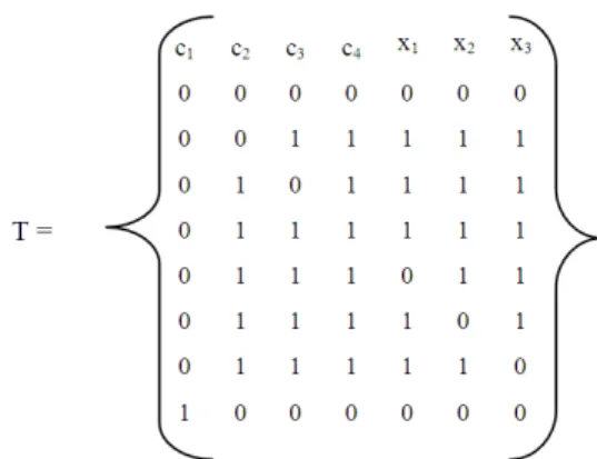
Fig. 3: Generalized test set
Fig. 4: Circuit for F= x1 ⊕ x2x3 ⊕ x1’x2x3
Fig. 5: Test vectors for the specific function F = x1
⊕ x2x3 ⊕ x1’x2x3
Test vectors: The test set has (n+5) vectors; each of the vectors is (n+4) long, ‘n’ being the number of data inputs. The first four columns of the matrix represent the control inputs c1 to c4 while the remaining n
columns that of the data inputs are x1 to xn. The
generalized test set is shown in Fig. 3.
The network and the set of test vectors for the specific function F = x1 ⊕ x2x3 ⊕ x1’x2x3 are shown in
Fig. 4 and 5 respectively.
Algorithm:
Step 1: Set up the circuit as in Fig. 4.
Step 2: Determine and connect the control lines c1 to
c4 as explained.
Step 3: Apply the test vectors as given in Fig. 5, one by one.
Step 4: For each test vector, determine the three outputs F, O1 and O2.
Step 5: Obtain the decimal equivalents of each of the above binary output sets.
Step 6: Simulate the specified type of fault at any pair of the control/data inputs.
Step 7: Repeat steps 1 to 4.
Step 8: Compare the set of outputs with the predetermined fault-free condition outputs Step 9: If the two output sets match exactly, it implies
that a fault, if present, is not identifiable or detectable; else, the fault is a detectable one. Step 10: Repeat steps 5 to 8 for the specified type of
fault at the other control and data inputs.
RESULTS
The following examples were considered and simulated with MATLAB coding and the results are tabulated in Table 1:
747 Table 1: Simulation results for a few logic functions
No. of Total
data possible Identifiability Distinguishability Function inputs faults factor (%) factor (%)
F1 3 42 92.86 47.62
F2 4 56 100.00 69.64
F3 5 72 98.61 52.78
F4 6 90 98.89 61.11
F5 7 110 100.00 56.36
F6 8 132 97.73 79.55
F7 9 156 100.00 61.54
F8 10 182 100.00 58.24
F9 11 210 100.00 55.24
F10 12 240 100.00 50.83
F2 = x1x2 ⊕x2’x3 ⊕x3’x4 ⊕ x1x2x3
F3 = x1’ ⊕x2x3’x4 ⊕x3x4’ ⊕x2’x3 ⊕x1x4x5
F4 = x1x2’⊕x2x3x4'⊕x4x5'x6
⊕x2x5⊕x2'x5'⊕x3'x2x1⊕x4x6
F5 = x1’x2x3 ⊕x4x5x6⊕ x4'x6'x7⊕x3x5x7
F6 = x1x2’x3⊕x4'x5x6'⊕x7x8'⊕x2x6x7'⊕x1'x6⊕x3'x4
⊕x1x5⊕x 4x5'⊕x5x7⊕x8x3x1⊕x3x5'x8
F7 = x1x2’x3’⊕x4x5’x6⊕x7’x8x9⊕x1’x4’x9’⊕x 2x5'⊕x3x5
F8 = x1’x2x3’ ⊕x4’x5’x6 ⊕x7x8'x9’ ⊕x10⊕ x6’x7⊕x8x10
F9 = x1 ⊕x2’x3x4' ⊕x5'x6x7’ ⊕x8x9x10⊕x10'x11⊕x1x3x9
F10 = x1’x2⊕x3x4'x5⊕x6x7’x8x9
⊕x10x11’x12⊕x1x2x3’⊕x4'x7
DISCUSSION
Numerical illustration:
Function considered:F = x1 ⊕x2x3 ⊕x1’x2x3
Fault-free output set {F, O1, O2} = {126, 112, 127}
The outputs of OR-bridging faults at lines c1 in
combination with c2, c3, c4, x1, x2 and x3 with post fault
values 00 and 11 are tabulated in Table 2 and 3.
Observations: Control inputs: c1 to c4;
Data inputs: x1 - x3
Total No. of Fault location pair combinations:
(nx+ nc) C2= 7C2=21
Where:
nx = The number of data inputs nc = The number of control inputs
Number of bridging faults for one pair of lines = 2 (Post fault value combinations {0, 0} and {1, 1}).
Total number of bridging faults for the three variable function used is 21*2=42.
For fault free condition, the output set is:
{F, O1, O2} = {126, 112, 127}
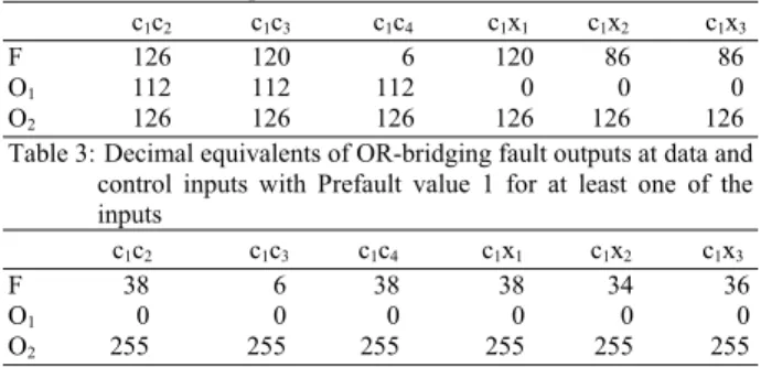
Table 2: Decimal Equivalents of OR-bridging fault outputs at data and control inputs with Prefault value 0 for both the lines
c1c2 c1c3 c1c4 c1x1 c1x2 c1x3
F 126 120 6 120 86 86
O1 112 112 112 0 0 0
O2 126 126 126 126 126 126
Table 3: Decimal equivalents of OR-bridging fault outputs at data and control inputs with Prefault value 1 for at least one of the inputs
c1c2 c1c3 c1c4 c1x1 c1x2 c1x3
F 38 6 38 38 34 36
O1 0 0 0 0 0 0
O2 255 255 255 255 255 255
When the Post fault outputs are identical as of fault free one, then those faults are termed as unidentifiable faults. For the example considered, the number of unidentifiable faults is 3.
∴the Identifiability Factor is (42-3)/42×100 = 92.86%
When the post fault outputs are same for different combinations of faults, then those faults are termed as Indistinguishable faults. For the given example, the output sets that get repeated are as follows:
{86, 0, 126} 2 times {38, 0, 255} 3 times {0, 0, 127} 3 times {86, 0, 127} 4 times {120, 0, 127} 2 times {126, 114, 255} 3 times {126, 116, 255} 3 times {126, 120, 255} 2 times
Thus totally repetition occurs for 22 fault location combinations.
Hence overall distinguishability factor is:
(42-22) /42×100 = 47.62%
However, when the individual cases are considered the distinguishability factor can be seen to be appreciably high as illustrated in Table 1.
Same output set of {86, 0, 127} for the following fault combinations:
OR bridging fault with prefault value 0 at c2x2
OR bridging fault with prefault value 0 at c2x3
OR bridging fault with prefault value 0 at x1x2
OR bridging fault with prefault value 0 at x1x3
The distinguishability for this set is:
748 Similarly, the output set {38, 0, 255} occurs 3 times, for which the distinguishability factor is (42-3)/42×100 = 92.86%.Though the overall distinguishability is small, it does not affect the detection capability. Further, the distinguishing capability for an individual output set can be quite high, as illustrated above.
Further, the location of fault can also be easily diagnosed from the output set. For instance if the output set is {86, 0, 127} then the fault condition would be one of the four cases discussed above involving c2, c3, x1
and x2 and hence those lines only need to be checked.
CONCLUSION
A test set scheme for detection of OR-bridging faults for ESOP RMC logic functions have been proposed and the simulation results show that the proposed scheme reduce the possibility of unidentifiable faults for the specified type of function. The location can also be diagnosed through the output set. The analysis and diagnosis have been done through compact tabulation and two quantification indices. All possible combinations of the data and control line pairs have been considered.
REFERENCES
Bhattacharya, B.B. et al., 1985. Testable design of RMC networks with universal tests for detecting stuck-at and bridging faults. IEE Proc. Comput. Digital Tech., 132: 155-162. DOI: 10.1049/ip-e:19850022
Drechshler, R. et al., 1997. Testability of 2 level AND/EXOR circuits. Proceeding of the European Design and Test Conference, pp: 548-553. DOI: 10.1109/EDTC.1997.582415
Kalay, U., D.V. Hall and M.A. Petrowski, 2000. A minimal universal test set for self-test of exor-sum-of-products circuits. IEEE Trans. Comput., 49: 267-276. DOI: 10.1109/12.841130
Neelakantan, P.N. and A.E. Jeyakumar, 2006a. Single Stuck-at fault diagnosing circuit of Reed-Muller canonical exclusive-or sum of product Boolean expressions. J. Comput. Sci., 2: 595-599.
http://www.scipub.org/fulltext/jcs/jcs27595-599.pdf
Neelakantan, P.N. and E.A. Jeyakumar, 2006b. stuck-at fault test vectors for exclusive-or sum Reed-Muller canonical Boolean functions. GESTS Int. Trans. Comput. Sci. Eng., 27: 139-147.
Pradhan, D.K., 1978. Universal test sets for multiple fault detection in and-exor arrays. IEEE Trans. Comput., 27: 181-187. DOI: 10.1109/TC.1978.1675057
Rahaman, H., D.K. Das and B.B. Bhattacharya, 2004. Testing of stuck-open faults in generalized Reed Muller and EXOR sum of products CMOS circuits. IEE Proc. Comput. Digital Tech., 151: 83-91. DOI: 10.1049/ip-cdt:20040031
Reddy, S.M., 1972. Easily testable realizations for logic functions. IEEE Trans. Comput., 21: 1183- 1188. DOI: 10.1109/T-C.1972.223475
Sasao, T., 1997. Easily testable realization for generalized Reed-Muller expressions. IEEE Trans. Comput., 46: 709-716. DOI: 10.1109/12.600830 Wu, H. et al., 1996. Generalized
partially-mixed-polarity Reed-Muller expansion and its fast computation. IEEE Trans. Comput., 45: 1084-1088. DOI: 10.1109/12.537134
Zhongliang, P., 2002. Testable realizations of ESOP expressions of logic functions. Proceeding of the of 11th Asian Test Symposium (ATS”02), IEEE
Computer Society. http://DOI.ieeecomputersociety.org/10.1109/ATS.2
002.1181701
Zhongliang, P., 2003. Bridging fault detections for testable realizations of logic functions. Proceeding of the of 16th International Conference on VLSI