Fiabilitate si Durabilitate - Fiability & Durability nr.1/2010
Editura “Academica Brâncuşi” , Târgu Jiu, ISSN 1844 – 640X
25
RESEARCH ON HYDRAULIC SERVO AMPLIFIERS USED IN
MARINE SYSTEMS
Assoc Prof. Ph.D. Eng. Ali BEAZIT, “Mircea cel Bătrân” Naval Academy, Constanţa,
900218, Romania, email: [email protected]
Prof. Ph.D. Eng. Gheorghe SAMOILESCU, “Mircea cel Bătrân” Naval Academy,
Constanţa, 900218, Romania, email: [email protected]
Prof. Ph.D. Eng. Sander CALISAL, UBC Mechanical Engineering Department, Vancouver
BC, Canada, V6R2T1, email: [email protected]
Lecturer Ph.D. Adriana SPORIS, “Mircea cel Bătrân” Naval Academy, Constanţa,
900218, Romania, email: [email protected]
Abstract: This paper presents numerical simulations for the mecano-hydraulic servoamplifier with a special kind of distributor. This distributor has different covering for the admission and evacuation flow. The purpose of this kind of distributor is to diminuate the high frequency auto-oscillations of the servoamplifier.
Keywords: servo-amplifier, self-oscillation, high frequency.
1. Scheme of the servo-amplifier and the distributor of different covarages between
admission and exposal
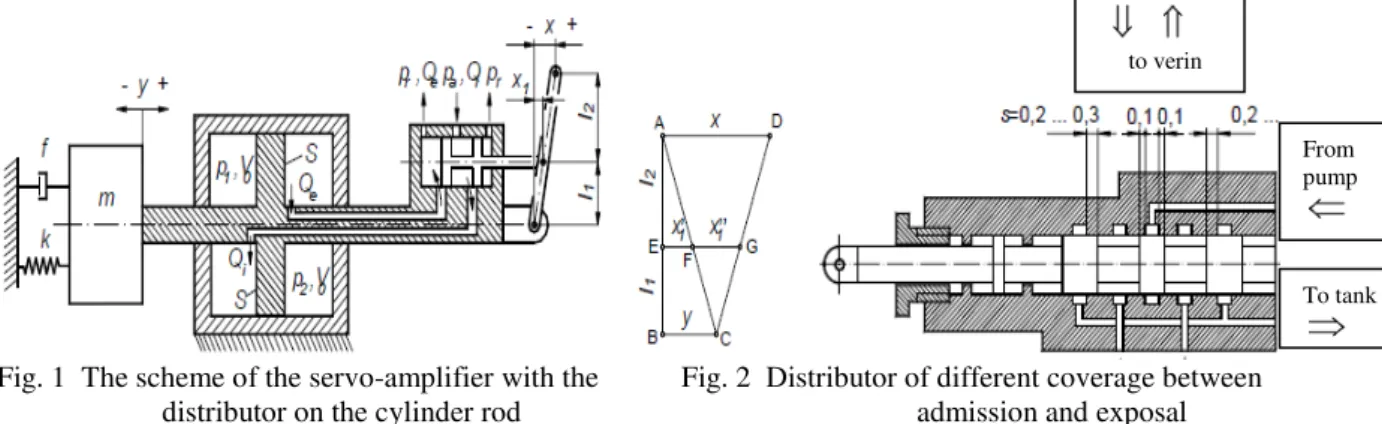
The scheme of a mechanical-hydraulic servo-amplifier with the distributor on the cylinder rod is presented in fig. 1.
Fig. 1 The scheme of the servo-amplifier with the Fig. 2 Distributor of different coverage between distributor on the cylinder rod admission and exposal
The necessary sizes for the functioning of this type of servo-amplifier are presented in the figure.One of the most important problems regarding the functioning of the mechanical-hydraulic servo-amplifiers is the self-oscillation phenomenon of high frequency. This consists of oscillations with frequencies up to 200Hz and amplitudes of several tenths of millimeters of the operated component. The frequency of these oscillations depends on the dimensions of the servo-amplifier cylinder, on the width of the distributor slots, on the characteristics of the hydraulic fluid and the operated m mass.
On the board of the hydrofoil ships, the frequency of these oscillations is big, because the mass of the command surfaces is reduced. The presence of these oscillations can induce the buzz-flutter phenomenon of the command surfaces in a transonic way, and can solicit when worn, the components in the chain of commands and the afferent structure of the command surfaces. Due to the big frequency of the oscillations and the reduced amplitude, the influence over driving of the hydrofoil ships is small, if the servo-amplifier is of an irreversible type.
From pump
To tank
Fiabilitate si Durabilitate - Fiability & Durability nr.1/2010
Editura “Academica Brâncuşi” , Târgu Jiu, ISSN 1844 – 640X
26
The construction solutions to eliminate the high frequency oscillations are varied and among them there are: using distributors with triangular slots, using controlled fluid losses between the servo-amplifier cells, using distributors of different coverage between admission and exposal, using hydraulic networks of reducing the oscillations. Each of these methods has both advantages and disadvantages.
Using a distributor of different coverage between admission and exposal has the advantage of not reducing the frequency of the servo-amplifier and maintains the high rigidity of the hydraulic action, but it does not completely eliminate the high frequency oscillations but their fast decrease.
The scheme of the distributor of different coverage between admission and exposal is presented in fig. 2 [1].
The functioning principle consists in a stagger between the opening of the admission and exposal slots, so that the fluid in the cell out of which the exposal takes place, to be comprised and to take over the pressure impulses that appear at the opening of the admission slots. This way the possibility of movement of the piston is reduced and the high frequency oscillations, which will further propagate in the chain of commands, will have the amplitude lowered to the value determined by the compressibility of the fluid, a value which is lower than the one obtained in the case of the distributor with rectangular slots with perfect coverage.
We mention the fact that the oscillation phenomenon of high frequency appears even if the distributor has positive coverage, but equal for the admission and exposal slots.
This system uses positive coverage to the distributor, which leads to the introduction of a non-linearity of the delay type for the admission and exposal outputs. The mathematical modeling on the linear patterns is not suitable for studying such servo-amplifiers, but the study with the help of patterns with non-linear mass outputs can simply be developed out of the mathematical pattern of the servo-amplifier with rectangular slots [2].
2. The functioning equations of the servo-amplifier
By noting with a1 and a2the admission and exposal coverage, and considering the servo-amplifier of the one in diagram 1, we obtain the equations of the massic outputs Qim
and Qem, (1) and (2):
r r d r r d a a d a a d p p a y x l l l p p a y x l l l L p p a y x l l l p p a y x l l l L p p a y x l l l p p a y x l l l L p p a y x l l l p p a y x l l l L a y x l l l a 1 2 2 1 1 1 2 2 1 1 1 2 2 1 1 1 2 2 1 1 1 1 2 1 1 1 1 2 1 1 1 1 2 1 1 1 1 2 1 1 1 2 1 1 2 , ) ( 2 ) ( , ) ( 2 ) ( , ) ( 2 ) ( , ) ( 2 ) ( ) ( 0 r r d r r d a a d a a d p p a y x l l l p p a y x l l l L p p a y x l l l p p a y x l l l L p p a y x l l l p p a y x l l l L p p a y x l l l p p a y x l l l L a y x l l l a 2 2 2 1 1 2 2 2 1 1 2 2 2 1 1 2 2 2 1 1 2 1 2 1 1 2 1 2 1 1 2 1 2 1 1 2 1 2 1 1 2 2 1 1 1 , ) ( 2 ) ( , ) ( 2 ) ( , ) ( 2 ) ( , ) ( 2 ) ( ) ( 0 (1) In order to determine the pressures in the cylinder cells we use the next state equation of
the hydraulic fluid,
0(1 p) (2)
Fiabilitate si Durabilitate - Fiability & Durability nr.1/2010
Editura “Academica Brâncuşi” , Târgu Jiu, ISSN 1844 – 640X
27
The following pressures result:
1 ) ( 1 0 10 1 y l S dt Q m p t im ; 1 ) ( 1 0 20 2 y l S dt Q m p t em (3)
To these equations the movement equation of the operated m mass, ky
dt dy f S p p dt y d
m ( 2 1)
2 2
(4)
For the numerical simulation is useful the non-dimensioning of the equations. Using the notes
a p p p 1 1 ; a p p p 2 2 ; a r r p p p ; m ax x x x ; m ax x y y ; m ax 1 1 x a a ; m ax 2 2 x a a ; T t t ; 2 1 1 1 l l l
k ;k1 dLxmax 2 pa ;
max 2 2 mx ST p
k a ;
m f T k3 ;
m kT k 2 4 ; m ax 0 Lx p V T d a
where xm ax represents the maximum opening of the distributor, the following formulas result
[3]: 1 ) ( 1 m ax 0 10 1 y l Sx dt Q m p p t im a
; 1
) ( 1 max 0 20 2 y l Sx dt Q m p p t em a k y t d y d k p p k t d y d 4 3 1 2 2 2 2 )
( (5)
r l r l r l r l l l l p p a y x k p p a y x k k p p a y x k p p a y x k k p a y x k p a y x k k p a y x k p a y x k k a y x k a 1 2 1 2 1 1 2 1 2 1 1 1 1 1 1 1 1 1 1 1 1 1 1 2 , ) ( ) ( , ) ( ) ( 1 , ) ( 1 ) ( 1 , ) ( 1 ) ( ) ( 0 r l r l r l r l l l l p p a y x k p p a y x k k p p a y x k p p a y x k k p a y x k p a y x k k p a y x k p a y x k k a y x k a 2 2 2 2 1 2 2 2 2 1 2 1 2 1 1 2 1 1 2 1 1 2 1 1 , ) ( ) ( , ) ( ) ( 1 , ) ( 1 ) ( 1 , ) ( 1 ) ( ) ( 0 (6)
3. The numerical simulation and the obtained results
For the numerical simulation of this type of servo-amplifier we have considered the following values for the sizes that intervene:
a
p =50 bar; d= 0,7; L =10 mm; =1050 kg/m3; xm ax=2 mm; m = 80 kg; f=60Ns/m; k
=1,3 106 N/m; dtija=30 mm; dpiston=50 mm; l = 60 mm; S=1,256 10
-3
m2; E 1/ = 2000
MPa.
Out of the numerical simulation of the functioning of this type of servo-amplifier several interesting aspects result.
Fiabilitate si Durabilitate - Fiability & Durability nr.1/2010
Editura “Academica Brâncuşi” , Târgu Jiu, ISSN 1844 – 640X
28
We realized a numerical study regarding the optimal choice of these two sizes. We used an entry signal composed of a ramp that increases from 0 to x=5 in a time of 100 T followed by the plateau at this value.
By giving different values to a1 and a2, we have observed that an optimal choice of these values can be made. For a1 the considered values have been [0; 0,02; 0,04; 0,06; 0,08; 0,1; 0,12] mm, which, if being adimensionalized with the maximum opening of the distributor, become a1 =[0; 0,01; 0,02; 0,03; 0,04; 0,05; 0,06], and for a2 [0,12; 0,15; 0,18;
0,21; 0,24; 0,27; 0,3] mm, which, if being adimensionalized, become a2 =[0,06; 0,075; 0,09;
0,105; 0,12; 0,135; 0,15].
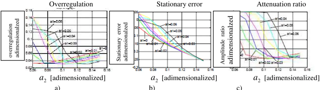
For each of these pairs the answer in time of the servo-amplifier was lined at the specified signal and the maximum amplitude of the high frequency oscillations, the stationary error and the report of two successive maxima were determined, which offer a better image over the amortization level of the oscillations. The graphics in diagram 3 were obtained, out of which the following conclusions can be drawn [4], [5].
The stationary error increases at the same time with the coverage at exposal a2. An interesting aspect is that in order for the coverage at admission a1 between 0,02 and 0,1 mm, considered for the exposal coverage a2= 0,12 mm, the oscillations are produced around a point which corresponds to a bigger movement of the stick than the one corresponding to the applied signal.
The high frequency oscillations are not at all diminished in these cases. Therefore, this is an area to be avoided in the construction of the servo-amplifier.
Regardless of what the coverage at admission is, the amplitude of the first maximum (overregulation), presents a minimum depending on the exposal coverage a2. It cannot be specified an optimum report between the two coverages, but the minimum can be found between a2= [0,07; 0,135] and it monotonously increases in proportion to the admission
coverage. The optimum report a2/a1 monotonously decreases to 37,5 when a1= 0,01 at 2,3
when a1= 0,12.
The ratio of two successive maxima of the high frequency oscillations is presented in diagram 3.c. this offers an image over the attenuation made by the servo-amplifier. It is observed the fact that, like this report, it presents a minimum for each of the considered coverages at admission.
Although the dimensioning of the servo-amplifier distributor can be optimized in proportion to the two coverages, so that good dynamic qualities may be obtained. However, it is observed that through this method of attenuation of the high frequency oscillations, these do not completely disappear, as it can be seen in diagram 4, which presents the variation of the servo-amplifier state parameters for an input signal mentioned above, and the coverages
1
a = 0,03 and a2= 0,12.
In figures 5 and 6 the variations of the servo-amplifier state parameters are presented for the case of a sinusoidal input signal, with the adimensionalized amplitude Ax= 10 and the
adimensionalized pulsation = 8 10-3 and = 8 10-4 .
For all the presented cases, the algorithm of numerical simulation in the SIMULINK programme was Dormand-Prince with variable pitch, with an imposed relative error of 10-12.
Fiabilitate si Durabilitate - Fiability & Durability nr.1/2010
Editura “Academica Brâncuşi” , Târgu Jiu, ISSN 1844 – 640X
29
Overregulation Stationary error Attenuation ratio
a2 [adimensionalized] a2 [adimensionalized] a2 [adimensionalized] a) b) c)
Fig. 3 The variation of the high frequency oscillations parameters for the case of the distributor with different coverages at admission and exposal
In order to compare, in figure 4 it is presented the variation of the output signal for the case of the distributor with perfect coverage, the same parameters of the servo-amplifier. It can be observed the higher amplitude of the oscillations and the fact that their amplitude remains constant in time [5].
x input signal y output signal p1 pressure p1 p2 pressure p2
t [adimensionalized] t [adimensionalized] t[adimensionalized] t[adimensionalized]
a) b) c) y output signal
t [adimensionalized]
d)
Fig. 4 Variation of the state parameters for the ramp input signal followed by the plateau at
x
A =5, a1= 0,03, a2= 0,12
x y p1 p2
t[adimensionalized] t[adimensionalized] t[adimensionalized] t[adimensionalized]
a) b) c) d)
Fig.5. Variation of the state parameters for the sinusoidal input signal
=8 10-3 , Ax=10, a1= 0,03, a2= 0,12
o
v
er
re
g
u
la
ti
o
n
ad
ime
n
si
o
n
al
ze
d
S
ta
ti
o
n
ar
y
er
ro
r
ad
ime
n
si
o
n
al
ze
d
A
mp
li
tu
d
e
r
at
io
ad
im
en
sio
n
alze
Fiabilitate si Durabilitate - Fiability & Durability nr.1/2010
Editura “Academica Brâncuşi” , Târgu Jiu, ISSN 1844 – 640X
30
x y p1 p2
t[adimensionalized] t[adimensionalized] t[adimensionalized] t[adimensionalized]
a) b) c) d)
Fig. 6. Variation of the state parameters for the sinusoidal input signal
=8 10-4 , Ax=10, a1= 0,03, a2= 0,12
4. Conclusions
This method of attenuation of the oscillations of a servo-amplifier gives good results in the case of the ramp followed by plateau type of input signals. In this situation, the coverage values can be chosen in such a way to minimize the attenuation time. For the low frequency sinusoidal input signals, the high frequency oscillations are diminished in amplitude as opposed to the case of the distributor with perfect coverage, but they do not completely disappear. For this other attenuation methods must be used.
References
[1]. Lungu A., Maşini şi acţionări hidraulice, Bucureşti, Editura Tehnică, 1999, pag. 236 -245.
[2]. Călinoiu, C., ş.a. Modelarea, simularea şi identificarea experimentală a servomecanismelor hidraulice. Bucureşti, Editura Tehnică, 1998, pag.45-70.
[3]. Vasiliu, N ., s.a. Servomecanisme hidraulice şi pneumatice vol. I, Bucureşti,
Universitatea “Politehnică”, 1992, Litografiat.
[4]. Popa I., Instalaţii hidropneumatice navale, Editura Academiei navale „Mircea cel
Bătrân”, Constanţa, 2007, pag.86-90.
[5]. Petre P, Nicolae I., Acţionări hidraulice şi automatizări, Edidura Nausicaa, Bucureşti,