Metalurgia & Materiais
Resumo
Os aços microligados são usados em peças automo-tivas forjadas, tais como girabrequins e bielas. Essas pe-ças são trabalhadas a quente em uma seqüência de está-gios, que inclui o aquecimento até a temperatura de en-charque, seguido por vários passes de forjamento, e, fi-nalmente, há um resfriamento controlado para definir a microestrutura e propriedades mecânicas. Nesse traba-lho, foram investigados o comportamento termomecâni-co e a evolução microestrutural de um aço microligado Ti-V na região de transição de fase. Os testes de torção foram feitos em múltiplos passos com deformação verda-deira de 0,26 em cada passo. Após cada passo de torção, as mostras foram resfriadas continuamente por 15 segun-dos para simular as condições de forjamento a quente. Esses testes forneceram resultados da temperatura de início de transformação de fase e permitiram analisar as mudanças de microestrutura. Foram, também, realizados os testes de trabalhabilidade para analisar a evolução mi-croestrutural por microscopia ótica e eletrônica de varre-dura. Os resultados dos testes de torção mostraram que a temperatura de início de transformação de fase está em torno de 700°C. Os testes de trabalhabilidade feitos a 700°C seguidos por resfriamento em água apresentaram microes-truturas com características distintas: regiões encruadas e de recristalização estática e dinâmica. Os testes de traba-lhabilidade de 700°C seguidos por resfriamento ao ar mos-traram uma complexa microestrutura de ferrita, bainita e martensita, enquanto que os testes feitos em 650 e 600°C seguidos por resfriamento em água apresentaram uma mi-croestrutura com ferrita alotriomórfica presente nos con-tornos de grão da austenita.
Palavras-chave: Aço microligado, decomposição da austenita, análise numérica, evolução microestrutural.
Abstract
Microalloyed steels are used in the forging of many automotive parts like crankshafts and connecting rods. They are hot worked in a sequence of stages that includes the heating to the soaking temperature, followed by forging steps, and finally the controlled cooling to define the microstructure and mechanical properties. In this work it was investigated the thermomechanical behavior and the microstructural evolution of a Ti-V microalloyed steel in the phase transition region. Torsion tests were done with multiple steps with true strain equal to 0.26 in each step. After each torsion step the samples were continuous cooled for 15 seconds to simulate hot forging conditions. These tests provided results for the temperature at the beginning of the phase transformation, and allowed to analyze the microstructural changes. Also, workability tests were held to analyze the microstructural evolution by optical and scanning electron microscopy. Results from the torsion tests showed that the temperature for the beginning of phase transformation is about 700 oC.
Workability tests held at 700 oC followed by
water-cooling presented microstructures with different regions: strain hardened, and static and dynamic recrystallized. Workability tests at 700 oC followed by air-cooling
showed a complex microstructure with ferrite, bainite and martensite, while tests at 650 and 600 oC followed
by water-cooling showed a microstructure with allotriomorphic ferrite present in the grain boundaries of the previous austenite.
Keywords: Microalloyed steel, austenite decomposition, numerical analysis, and microstructural evolution.
Effects of deformation on the
microstructure of a Ti-V microalloyed steel
in the phase transition region
Wiliam Regone
Associate Researcher. State University of Campinas. School of Mechanical Engineering - Campinas, SP, Brazil E-mai: [email protected]
Sérgio Tonini Button
1. Introduction
Hot forging of microalloyed steels is used to the manufacturing of many automotive components. The process flowchart begins with the heating to soaking temperatures in the austenitic region, followed by forging steps that defines the product geometry and dimensions. Finally, these products are cooled to obtain the desired properties [1].
The metallurgical mechanisms present during these processes are the strain hardening, the softening, the precipitation, and phase transformations. Strain hardening is caused by deformation and at a proper process temperature can lead to the thermal softening, competing with the particles precipitation that will affect the material strength. Therefore, during hot forging, these metallurgical mechanisms will control the microstructural evolution of the austenitic grains. The strain hardening causes the increase in the dislocations density [2]. Dynamic recovery involves the annihilation of these dislocations generating cells and sub-grains. Increasing the strain hardening, the equiaxial grains will elongate and sites favorable to the nucleation of new grains will appear in the boundaries of these elongated grains [3].
Dynamic recrystallization begins when the first nuclei restore the microstructure only locally, while the rest of the material keeps on hardening. The recrystallized nuclei grow just after the deformation is ended by metadynamic recrystallization [4].
Static recovery takes place after the deformations and partially restores the microstructure. The total softening only occurs with the recrystallization that begins after a necessary incubation time with the nucleation of new grains free of deformation [5].
The final properties of hot forged products are basically determined by the microstructure defined at the end of the process. Therefore it is very important to know how the phase transformations occur during the cooling stage.
The transformation of the austenite presents two mechanisms: one diffusional with the nucleation and growth of new phases, like with the allotriomorphic ferrite that nucleates in the grain boundaries of the austenite, forming layers that follow the limits of these boundaries. [6]. The second mechanism is the martensitic transformation that is associated to high cooling rates and is caused by the shearing of the microstructure [7].
2. Material and methods
A great variety of microalloyed steels with low and medium carbon contents have been used to the manufacturing by hot forging of many automotive components. The interest in forged parts with microalloyed steels is related to the thermomechanical processing of these steels, because it is possible to achieve high mechanical strength and toughness simply with air cooling directly after forging, thus eliminating the usual normalizing heat treatment, reducing process times and production costs.In this work it was analyzed the thermomechanical behavior and the microstructural evolution of a V-Ti microalloyed steel in the region of phase transition. A sequence of torsion tests was carried out with controlled deformations and continuos cooling. Also, workability tests were held in many temperatures followed by air-cooling or water-cooling to reveal the microstructures present in the workpieces.
The material studied in this work was a commercial medium carbon microalloyed steel used in the manufacturing of automotive components by hot forging followed by controlled air cooling. The chemical
composition of this steel is shown in Table 1. This material in the condition "as hot rolled and air-cooled" was re-rolled between 1150 and 1200°C to bars with 18 mm in diameter. No subsequent heat treatment was held in order to preserve material properties common to industrial hot forging operations [8].
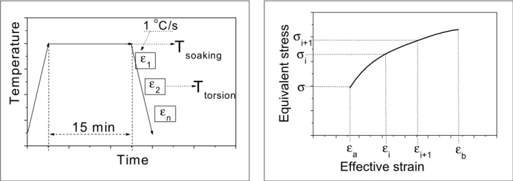
The tests with multiple deformation steps (ε1, ε2,..., εn) by hot torsion with continuous cooling applied a method similar to that used by many authors [9-11]. These tests were done with the heating of the workpieces to the temperature of 1050 or 1200°C, at a soaking time of 15 minutes.
Then these workpieces were continuously cooled at the cooling rate of 1°C/s, as shown in Figure 1. Each test had 19 deformation steps, with interval time of 30 seconds, mean strains of 0.3 and mean strain rate equal to 1 s-1.
With the results obtained in the torsion tests the mean equivalent stress was calculated with the Expression (1) for each deformation step to plot a curve similar to that shown in Figure 2 [12]:
∫
−
=
b
a
εε eq eq a
b
eq
σ
d
ε
ε
ε
1
σ
(1)Where (εb-εa) corresponds to the equivalent strain of the deformation step.
Workability upsetting tests were carried out with workpieces machined with 15 mm in diameter and 20 mm high, and deformed in a hydraulic press. The upper die similar to an edge was chosen to promote a severe strain gradient inside the workpiece. This upper die was moved at 15 mm/s with a mean nominal strain rate of 0.93 s-1. The workpieces were heated at 1100°C held for 15 minutes and cooled with a mean rate of 4.5°C/s to
Table 1 - Chemical composition of the microalloyed steel (wt.%).
C Mn Si Al S P Ti V N
700, 650 and 600°C. Then the workpieces were deformed and air-cooled or water-air-cooled. Figure 3A shows the dies and workpiece before the deformation, and Figure 3B, the workpiece after hot forged.
Workpieces from the torsion tests and from the upsetting tests were analyzed by optical and electron scanning microscopy.
To reveal the microstructures the samples were grinded and polished with alumina (granulometry 1 and 0,5 µm.
Water-cooled samples were etched with an aqueous solution saturated of picric acid and detergent to reveal the austenitic grains. All samples were immersed in this solution heated to 80°C for 60 to 120 seconds, followed by a light polishing with alumina 0.3 µm to better observe the austenite grain boundaries. This procedure was repeated many times till satisfactory results were obtained [13].
Air-cooled samples were etched with nital 2% solution to reveal the microstructures formed from the austenite decomposition.
3. Results and
discussion
3.1 Torsion tests with
multiple deformation steps
with continuous cooling
To analyze the thermomechanical behavior of a V-Ti microalloyed steel, many deformation sequences with continuous cooling were carried out. Figures 4A and 4B show the results obtained in these tests for the equivalent stress as a function of the effective
Figure 1 - Sequence of torsion steps (ε1, ε2, ..., εn) with
continuous cooling.
ε
nε
21
oC/s
T
torsionT
em
per
at
ur
e
Time
15 min
T
soakingε
1Figure 2 - Equivalent flow stress as a function of effective
strain in torsion steps.
Effective strain
ε
i+1ε
iε
bε
aEqui
val
ent str
e
ss
σ
i+1
σ
iσ
Figure 3 - A) - Workpiece and dies before the deformation. B) Workpiece after hot forged. Mean dimensions in mm.
Flat die
Workpiece
Edge die
strain. Figure 5A and 5B show results for the equivalent mean stress (EMS) as a function of the temperature characteristic of each torsion step.
The results in Figure 4A correspond to workpieces heated to 1200ºC for 15 minutes, cooled at a cooling rate of 1ºC/s, and then deformed in a sequence of 16 torsion steps before the rupture of the workpieces, with an interval time of 30 seconds, mean strain of 0.3, and mean strain rate of 1s-1.
Results in Figure 4B were obtained with a similar procedure, but with a initial temperature of 1050ºC, and only 10 torsion steps before the rupture.
Figures 4A and 4B show that most of the deformation steps were held in the austenitic region and few steps were held in the phase transition as shown by the material rupture. The aspect of the flow curves indicated that strain hardening prevails during the passes and that in the interval time static recovery and static
recrystallization must take place softening the material and causing a small reduction in the equivalent stress. After several torsion steps effective strain is high enough to initiate the dynamic recrystallization and the reduction in the equivalent stress is more pronounced [14-15].
In Figures 5A and 5B it can be observed in the austenitic region that EMS increases with the temperature fall till the beginning of the phase transition
Figure 4 - A) Flow curves of the torsion steps. Initial temperature: 1200ºC. B) Flow curves of the torsion steps. Initial temperature:
1050ºC.
0
1
2
3
4
5
6
7
0
50
100
150
200
250
300
Step #6,1050 OC
Rupture
Step #1, 1200 OC
E
qui
valen
t st
ress (M
P
a
)
Effective strain
0
1
2
3
4
5
6
7
0
50
100
150
200
250
300
Step #6, 901 0C
Rupture
Step #1, 1050 0C
E
q
ui
va
le
n
t st
re
ss (
M
P
a
)
Effective strain
A)
B)
Figure 5 - A) EMS variation plotted from the results of Figure 4A. B) EMS variation plotted from the results of Figure 4B.
6,6 7,2 7,8 8,4 9,0 9,6 10,2
40 80 120 160 200 240 EM S ( M Pa)
10000/T (K-1)
1200 1000 800
Ar3
reduction of EMS
Tnr
766 0C
905 0C
T (0C)
6,6 7,2 7,8 8,4 9,0 9,6 10,2
40 80 120 160 200 240 E M S (M Pa)
10000/T (K-1)
1200 1000 800
reduction of EMS
Ar3
7630C
T (0C)
at the temperature Ar3 as indicated in the graphs. Figure 5A can be divided into three different regions considering the metallurgical mechanisms acting during the tests. Figure 5B shows only two of these regions.
In the first region, shown before the non-recrystallization temperature (Tnr~905°C), the main metallurgical mechanisms are the strain hardening, the dynamic recovery and the dynamic recrystallization during the deformation,
and the static recovery and static recrystallization in the interval between the steps. In the second region, between Tnr and Ar3 the precipitation induced by deformation takes place and fine particles are precipitated in the boundaries of the austenite grains. These particles block the boundaries and inhibit that between the deformation steps the static recovery and recrystallization restore the material [16]. Therefore, the strength is increased by the precipitation and by the
temperature fall. In the third region, defined after Ar3 at a temperature near to 766°C, ferrite is formed in the austenite boundaries reducing the material strength and causing its rupture.
Figure 5B does not show a defined Tnr since the initial temperature of 1050°C was not enough to solubilize the precipitates into the austenite. The temperature to phase transformation Ar3 is found 763°C almost the same found in Figure 5A.
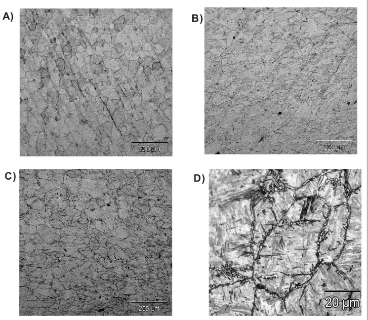
Figure 6 - A) Sample deformed at 700°C and water-cooled - non-deformed region. B) Sample deformed at 700°C and water-cooled
- region with low deformation.C) Sample deformed at 700°C and water-cooled - region with high deformation. D) Sample deformed at 700°C and water-cooled - region with high deformation. (optical microscopy).
A)
B)
3.2 Microstructural analysis
of samples from the
workability tests
With the results from the workability tests it was possible to evaluate the influence of the applied deformation and of the temperature in many regions of the workpiece, on the metallurgical mechanisms present in the deformation and cooling stages.
Figures 6A to 9F show the microstructures of samples heated to 1100°C for 15 minutes, cooled at a mean rate of 4.5°C/s, then deformed at 700, 650 or 600ºC, and finally water-cooled or air-cooled.
3.2.1 Samples deformed at 700°C and water-cooled
Figures 6A to 6D show the microstructures and obtained for these samples in three regions: without deformation, low deformation, and severe deformation.
Figure 6A shows non-deformed austenite grains with a size of 50 µm that represent the condition before the deformation. Figure 6B shows hardened elongated grains. In this region, the deformation was not enough to initiate the dynamic recrystallization. Figure 6C shows small equiaxial grains generated by dynamic and metadynamic recrystallization. Figure 6D show a deformed region with a microstructure similar to martensite. It can be observed that in the grain boundaries some traces of allotriomorphic ferrite is already formed.
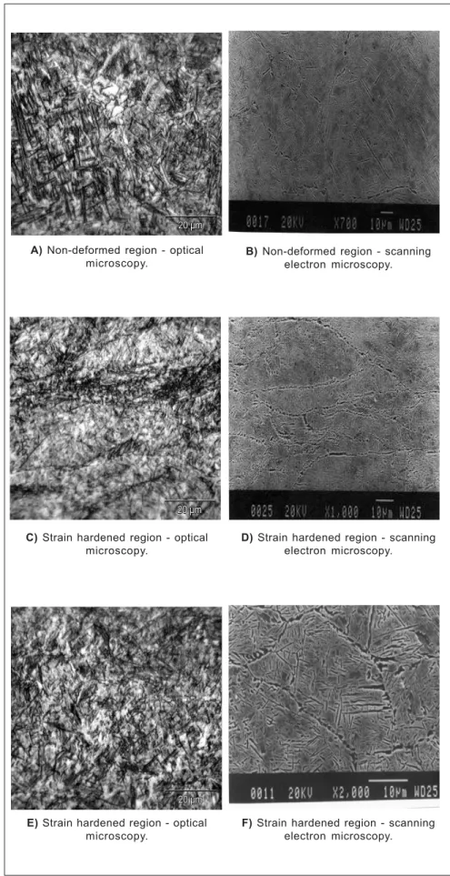
3.2.2 Samples deformed at 700°C and air-cooled
Figures 7A to 7F show the microstructures of these samples for the same regions analyzed in the item 3.2.1.
Since the workability tests were held near Ar3 it was observed a complex microstructure with different morphologies that difficult its
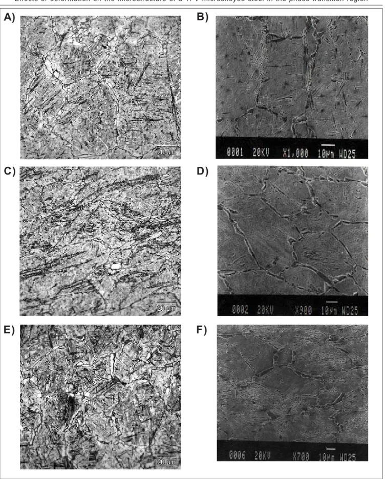
interpretation. Figure 7 - Sample deformed at 700 °C and air-cooled.
B) Non-deformed region - scanning electron microscopy.
A) Non-deformed region - optical microscopy.
D) Strain hardened region - scanning electron microscopy.
C) Strain hardened region - optical microscopy.
F) Strain hardened region - scanning electron microscopy.
Figure 7A (optical microscopy) shows a non-deformed region with a martensite microstructure and some idiomorphic ferrite grains, confirmed by Figure 7B obtained by electron microscopy, where the ferrite grains were formed in the austenite boundaries.
Figure 7C shows the microstructure of a deformed and strain hardened region. This same region is shown in Figure 7D by electron microscopy and it can be observed that the respective austenite grains were deformed but their interior are free of deformation due to the dynamic recovery.
Figure 7E also shows a deformed region with a complex morphology. Figure 7F (electron microscopy) shows that ferrite was formed in the austenite boundaries. In the interior of the austenite grains it can be observed the formation of bainite. The primary bainite needles nucleated in the boundaries and the secondary needles formed from the primary are found in the interior of the grains.
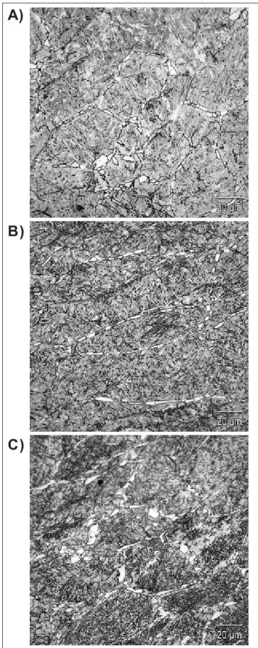
3.2.3 Samples deformed at 650°C and water-cooled
Again, these samples were analyzed in three regions: without deformation, low deformation, and high deformation. In these tests the material was in the region of transition from austenite to ferrite.
Figure 8A shows a non-deformed region with a microstructure similar to martensite with allotriomorphic ferritic grains in the boundaries of the previous austenite. Figure 8B shows similar results but with elongated austenitic grains and ferrite in the boundaries. Figure 8C shows austenitic grains deformed and recrystallized, with allotriomorphic ferrite in the austenite boundaries.
3.2.4 Samples deformed at 600°C and water-cooled
Figures 9A to 9F show the microstructures of three different regions (non-deformed, low deformation and high deformation) of samples upset in the workability tests at 600°C and water-cooled. At this temperature the material should present two phases, austenite and ferrite.
Figure 9A shows the microstructure of the non-deformed region with morphology similar to martensite with allotriomorphic ferrite in the previous austenite boundaries. The same microstructure can be observed by scanning electron microscopy in Figure 9B.
The region with low deformation is shown in Figures 9C and 9D and the microstructure shows deformed austenitic grains due to the intense strain hardening.
Figures 9E shows the microstructure of the region with high deformation. The morphology is similar to the martensite but the shape of the previous austenitic grains is not well defined because they could be strain hardened and elongated or restored by dynamic recovery. Figure 9F shows the same
Figure 8 - Sample deformed at 650°C and water-cooled. A)
Non-deformed region- optical microscopy. B) region with low deformation - optical microscopy. C) Region with high deformation - optical microscopy.
A)
B)
Figure 9 - Sample deformed at 600°C and water-cooled. A) Non-deformed region, optical microscopy. B) Non-deformed region, scanning electron microscopy. C) Region with low deformation, optical microscopy. D) Region with low deformation, scanning electron microscopy. E) Region with high deformation, optical microscopy. F) Region with high deformation, scanning electron microscopy.
A)
C)
E)
B)
D)
region by electron microscopy and it can be observed the previous austenitic microstructure with small bainite needles in the interior of the grains.
4. Conclusions
Results from the torsion tests showed that the temperature for the beginning of phase transformation is around 765°C for the microalloyed steel studied in this work.
Workability tests at 700°C followed by water-cooling showed that strain hardening, static and dynamic recrystallization can be present and form complex microstructures with ferrite and bainite mixed to the martensite. Tests held at 650 and 600°C with water-cooling presented a microstructure with allotriomorphic ferrite formed in the boundaries of the austenitic grains.
In the sequence of torsion tests with continuous cooling, the stress curves in the austenitic region showed an increase in the equivalent stress caused by the temperature fall and strain hardening.
The critical strain to promote dynamic recrystallization was reached and confirmed by the decrease in the equivalent stress relative to the next step, despite the temperature fall.
In the torsion tests at 1200°C the Tnr is near 905°C, while for 1050°C Tnr is not easily defined. The temperature to phase transformation is near 765°C for both temperatures 1200 and 1050°C.
The samples deformed in the workability tests at 700, 650 and 600°C
and water-cooled showed similar microstructures dependent on the local strain and temperature.
Non-deformed regions presented austenitic grains similar to those found in the material before deformation. The regions with low deformation showed elongated austenitic grains with allotriomorphic ferrite formed in the boundaries. Regions with high deformations presented mixed microstructures with elongated and fine recrystallized austenitic grains. By scanning electron microscopy it was possible to observe allotriomorphic ferrite formed in the boundaries and an interlaced structure of bainite needles in the interior of the austenitic grains.
5. Acknowledgements
Authors wish to thank CNPq -Conselho Nacional de Desenvolvimento Científico e Tecnológico and FAPESP -Fundação de Amparo à Pesquisa do Estado de São Paulo, for the financial support to this work.6. References
[1] REGONE, W., NEVES, F.O., BUTTON, S.T. Análise numérica do comportamento termomecânico e microestrutural de um aço microligado ao V-Ti em processamento análogo ao forjamento a quente. In: CONFERÊNCIA INTERNACIONAL DE
FORJAMENTO, 6. Gramado, RS, Anais...,
p. 113-125, october, 2002.
[2] LE MAY, I. Principles of mechanical
metallurgy. New York: Elsevier, 1981, Cap.6.
[3] MECKING, H., GOTTSTEIN, G. Recovery and recrystallization during deformation. In: HAESSNER, F. (Dr. Riederer) (Ed.).
Recrystallization of Metallic Materials. Verlag, 1978. p. 195-222.
[4] PETKOVIC, R. A., LUTON, M. J., JONAS,
J. J. Can. Met. Quart. v. 14, p. 137, 1975.
[5] McQUEEN, H. J., JONAS, J. J. Recovery and recristalization during hight temperature deformation. In: ARSENAUT,
R. J. (Ed.). Treatise on Materials Science
and Technology, v. 6, p. 393-493. New York: Academic Press, 1976.
[6] REGONE, W., NEVES, F.O., BUTTON, S.T. Análise do comportamento microestrutural de um aço microligado por simulação física análoga ao forjamento a
quente. In: CBECIMAT, 15. Anais... Natal,
november, 2002.
[7] GENTILE, F.C., REGONE, W., NEVES, F.O., BUTTON, S.T. Análise numérica e experimental da evolução microestrutural em forjamento a quente de um aço microligado ao V-Ti. In: CBECIMAT, 15.
Anais... november, 2002.
[8] OLIVEIRA, M. A. F. São Carlos: Federal University of São Carlos, 2001. (Doctorate Thesis).
[9] JONAS, J. J. Mat. Scie. and Eng., v. A184,
p. 155, 1994.
[10] BORATTO, F. et al. Thermec-88, ed. I. Tamura, Tokyo:1988. p. 383.
[11] SOUSA, R. C. São Carlos: Federal University of São Carlos, 1996. (Doctorate Thesis).
[12] BAI, D. Q., YUE, S., SUN, W. P., JONAS
J. J. Metall. trans. v. 24A, p. 2151, October,
1993.
[13] REGONE, W., BALANCIN, O. Modelagem e simulação de seqüências de deformações a quente para descrever e predizer a evolução microestrutural durante
o processamento metalúrgico. REM
-Revista Escola de Minas, v. 51, n. 1, p. 27-33, 1998.
[14] CABRERA, J. M., AL OMAR, JONAS, J.
J., PRADO J. M. Metall. trans., v. 28A,
p.2233, November, 1997.
[15] ELWAZRI, A. M., WANJARA P., YUE S.
Mat. Scie. and Eng., v. A339, p. 209, 2003.
[16] MEDINA, S. F. Mat. Scie. and Tech., v.
14, p. 217, 1998.
Artigo recebido em 09/09/2004 e aprovado em 15/11/2004.