ISSN 1517-7076 artigo e11787, 2017
Autor Responsável: Elisangela A. S. de Almeida Data de envio: 17/02/2016 Data de aceite: 21/ 12/2016
10.1590/S1517-707620170001.0119
Investigation of borided layers contribution
on the wear resistance and adhesion
of TiN coatings
Elisangela Aparecida dos Santos de Almeida1, César Edil da Costa 2, Júlio César Giubilei Milan 3, Anael Preman Krelling 4, Alexandre Galiotto 5
1,2,3
Mechanical Engineering Laboratory - PGCEM/UDESC, Centro de Ciências Tecnológicas - CCT - Rua: Paulo Mal-chitzki, Campus Universitário Prof. Avelino Marcante - Bairro: Zona Industrial Norte - CEP: 89225-100 - Joinville - SC - Brazil.
e-mail: [email protected] e-mail: [email protected]; [email protected]
4 Instituto Federal de Santa Catarina (IFSC), Rua: Pavão 1377 Bairro: Costa e Silva CEP 89220618 Joinville SC
-Brazil.
e-mail: [email protected] 5
Instituto Federal de Santa Catarina (IFSC),- Rua dos Imigrantes 455- Bairro: Rau - CEP 89254-430 - Jaraguá do Sul - SC - Brazil.
e-mail: [email protected]
ABSTRACT
The purpose of the investigation was to examine the possibility of improving tool life by reducing the wear effect and improving the adhesion of a thin film through a compound configuration that consists in boriding and PVD deposition. Single layer coatings of TiN were deposited by PVD (cathodic arc) on quenched and tempered and on borided powder metallurgy (P/M) AISI M2 steel. Adhesion test was performed according VDI 3198. Microhardness measurements were performed on Vickers scale and the tribological behavior evaluated through dry sliding wear test, using a ball-on-disk apparatus. The wear tracks were analyzed through scanning electron microscopy (SEM) and confocal microscopy. After the wear test the samples were transversally cut, coating and substrate were investigated using scanning electron microscopy (SEM). The results showed a better adhesion of the coating for the borided sample comparing to the quenched and tem-pered sample. The wear mechanisms of quenched/temtem-pered-TiN (Q/T-TiN) samples against Al2O3 ball were different from the wear mechanisms of borided-TiN (B-TiN) sample against Al2O3 ball.
Keywords: Coatings; Sliding wear; High speed steel; Adhesion; Boriding.
1. INTRODUCTION
The surface is the most important part in many engineering components; it has great influence on lifetime and performance of tools and machinery. Most part of the failures are originated on the surface, either by corrosion, wear or fatigue [1].
Ceramic coatings are used with the aim to protect the surface against wear, corrosion, erosion and other un-expected damage, improving material´s resistance where they are most needed. TiN coatings can be produced by physical vapour deposition (PVD) or chemical vapour deposition (CVD). It is largely used as a tribologi-cal coating because of its properties combination: high hardness, wear resistance, low friction coefficient and chemical inertness [2].
Good adhesion between the substrate and coating combined with a greater load bearing capacity are extreme-ly necessary for the durability enhancement [3].
Boriding can improve the substrate hardness and its wear resistance through the diffusion of boron at temper-atures varying from 840 and 1050 °C for steels [5, 6]. This thermochemical treatment promotes the formation of two different phases in the substrate surface: FeB and Fe2B [7]. The obtained hardness is about 1400 to 2100 HV, depending on the composition and structure of the borided layer, process time and temperature, and substrate composition [8-10]
Pack boriding method (EKABORTM2) was used to obtain boride underlayers on AISI 430 steel substrates, for the B4C deposition, by DC magnetron sputtering. This functionally graded multilayer promoted well ad-herent growth of boron containing ceramic coating [11].
Another study involving boriding treatment prior to the deposition was related to a microwave-plasma CVD process, where CoCrMo samples (ASTM F1537) were borided using a diborane (B2H6) and hydrogen (H2) feed gas mixture and coated with a nanostructured diamond film. Progressive load scratch and hardness tests show a robust surface layer not prone to brittle fracture for the borided surface, and results in good adhesion of the nanostructured film with low surface roughness [12].
The aim of this paper is the analysis of the contribution of borided layers on the wear resistance and adhesion of TiN coatings on a high speed steel produced by powder metallurgy (P/M). The P/M AISI M2 samples were borided using Ekabor 1-V2 powder and coated through a PVD commercial process (cathodic arc). The characterization of the compound (substrate and coating) was carried out by means of microhardness, surface roughness, adhesion and scanning electron microscopy. The tribological behavior was assessed through unlubricated ball-on-disk sliding wear test. The volume of removed material and the coefficient of friction were obtained. The wear track was analyzed by scanning electron microscopy and confocal micros-copy.
2. MATERIALS AND METHODS
Table 1 shows the composition of P/M AISI M2.
Table 1: P/M AISI M2 composition (% weight).
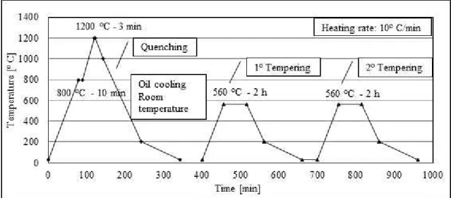
After uniaxial compression at 700 MPa the samples were sintered under vacuum at 1270 °C for 1 hour. Quenching and Tempering heat treatments were carried out as shown on the cycle of Figure 1.
Pack boriding method was used to obtain boride layers on P/M AISI M2 steel substrates. The samples were packed in the powder Ekabor 1-V2, and sealed in a stainless steel container. The container was placed in a resistance furnace. Boriding was performed at 1000 °C for 2 hours.
Both quenched and tempered and borided samples were coated in industrial-scale cathodic arc plating system. The polished samples were mounted on a rotational substrate holder. TiN coatings were deposited using Ti cathodes and reactive gas N2. The commercial process consists in the generation of vacuum in the chamber, followed by heating the system (substrate temperature for deposition was 550 °C), bombardment of the spec-imens with the purpose to clean the samples surface, deposition and cooling.
Roughness parameter (Ra value) was obtained after the deposition using a rugosimeter Mitutoyo Surftest 211, 18 measurements were obtained for each condition and the cut-off length was 0.8 mm. Cross-sections of the samples were observed using scanning electron microscopy (SEM). The samples were etched in 3% Nital solution. Adhesion test was performed according VDI 3198 by Rockwell-C indentation test. This is a reliable qualitative control test applied in layered compounds [13-15]. A load of 1471 N was applied to cause coating damage adjacent to the boundary of the indentation. The impression was evaluated using SEM. Cross section microhardness was assessed by Vickers microhardness tester Shimadzu HMV-2T using 25 g load, 9 meas-urements were obtained for each distance of the surface and indentation time of 10 seconds.
Sliding tests were performed on quenched/tempered AISI M2-TiN (Q/T-TiN) and on borided AISI M2-TiN (B-TiN) disks using a ball-on-disk sliding wear apparatus without lubrication. The counter-body used was a polished alumina (Al2O3) ball of 6 mm diameter. The test was carried at room temperature (~ 25 °C). The stationery ball was pressed with a load of 10 N to the disk rotating at a horizontal plane. The sliding speed was 0.1 m/s. The track radius was 4 mm, and the total sliding distance of 1000 m. The friction coefficient was obtained during the test, by the measurement of friction force. Profiles of the wear tracks were made on a confocal microscope, and the volume of removed material obtained using Mountains Map® software. Four tests were performed for each condition and four wear profiles obtained on each wear track.
3. RESULTS AND DISCUSSION
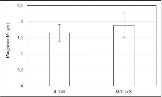
Figure 2 shows the results of roughness (Ra parameter).
Figure 2: Roughness Ra [µm].
The results indicated are statistically the same for these conditions with 95% of reliability. This parameter was measured after the deposition.
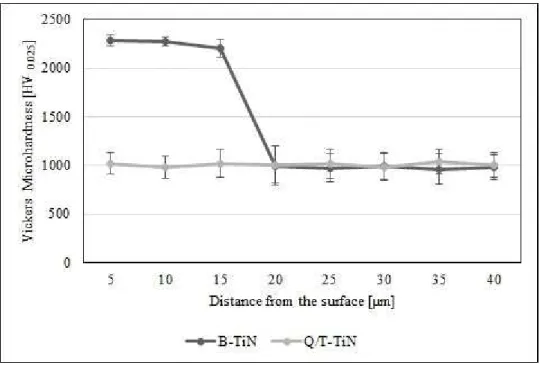
Figure 3: Microhardness profile of the samples B-TiN and Q/T-TiN.
The cross-sections of the samples are shown on Figure 4. The coating copies the topography of the sample. The typical carbides of the AISI M2 can be seen both on quenched and tempered samples and inside the borided layer for the borided samples. On Figures 4 b) and 5, of the borided samples, the dark region on the bottom of the image corresponds to the matrix.
Figure 4: Cross-section micrographs of samples a) Q/T-TiN and b) B-TiN.
The presence of these carbides (with micron and submicron size) inside the borided layers was previously discussed [10], which has shown that they are homogeneously distributed, have high fracture toughness, and can obstruct the crack propagation in the borided layer. These carbides are uniformly distributed and their sizes are similar to the ones found on the substrate.
Figure 5: Cross-section micrograph of the sample B-TiN (BSE - back scattered electrons).
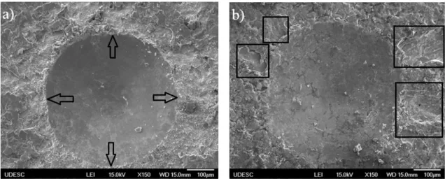
The adhesion test results show that boriding treatment increases the adhesion of the coating to the substrate. The SEM micrographs of VDI adhesion tests are show on Figure 6. Figure 6 a) shows unacceptable level of adhesion strength of the film to the quenched and tempered sample according to VDI 3198, due to the delam-ination at the vicinity of the indentation. The film was completely removed at the vicinity by the indentation as shown by the arrows. Figure 6 b) shows that the delamination is reduced when the sample is borided prior to the deposition (the delamination points are highlighted by the squares). This can be attributed to the higher hardness of the borided layer (approximately 2000 HV), combined with a higher load bearing capacity. A higher hardness of the substrate leads to a reduction of the interfacial residual stress, increasing the adhesion of the coating to the substrate [16].
Figure 6: SEM micrographs of VDI adhesion test on a) Q/T-TiN and b) B-TiN.
Figure 7 graphically represents the friction coefficients obtained during the wear test for the samples. These results are the average of the friction coefficients values in steady regime of four samples for each condition. The friction coefficient is lower for the B-TiN samples (0.6802 ± 0.0098). For Q/T-TiN samples the friction coefficient is about 0.7509 ±0.0148. There is a reduction of approximately 10% on the friction coefficient for the B-TiN samples.
coating delamination, which release hard particles of the film that were trapped in between the ball and the disk.
Figure 7: Friction coefficient of the samples.
The change in the wear mechanism is evidenced by the volume loss results indicated for the Q/T-TiN sam-ples in contrast with the negative results indicated by the B-TiN samsam-ples, in Figure 8. These results indicate that for the B-TiN samples there was adhesion of material in the wear track.
Figure 8: Volume of removed material.
Figure 9: SEM micrographs of wear tracks a) Q/T-TiN b) B-TiN.
Figure 10 shows the qualitative chemical analysis (EDS mapping - Energy Dispersive Spectroscopy) ob-tained for the samples Q/T-TiN.
Through the analysis it is observed that there was great oxidation on the edge of the track, due to the presence of small wear particles, that during the ball-on-disk test were pushed to this position. The constituents of the coating Ti and N are presented in reduced quantity on the track indicating some removal of the coating and Fe is more evident on the track, indicating exposure of the substrate.
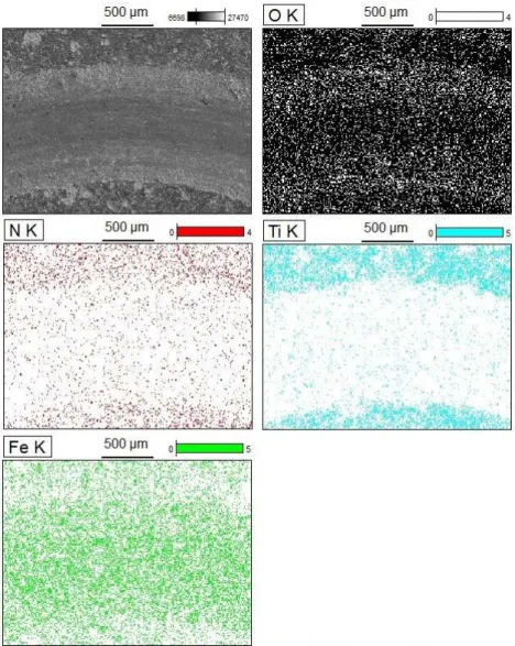
Comparatively Figure 11 of B-TiN samples shows greater presence of oxygen in the middle of the track, and the presence of small wear particles is not clearly detected through the image.
Figure 11: Worn track and EDS mapping of B-TiN sample.
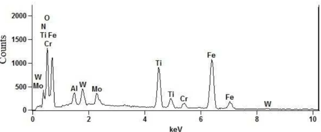
Figure 12: EDS spectrum of a point in the middle of the wear track of the B-TiN sample.
Al component is neither a constituent of the coating and nor a constituent of the substrate. This spec-trum indicates that there was some wear of the ball (Al2O3), and adhesion of the ball constituents on the wear track. The presence of the ball debris is attributed to the ball wear.
Considering that the ball hardness is 1660 ± 50 HV1 (informed by the supplier), it means that it is 17% lower than the borided layer hardness, 33% lower than the film hardness and 40% higher than the quenched and tempered substrate. As the tests confirmed a better adhesion of the film on the substrate for the B-TiN samples it is also confirmed a better load bearing capacity for the borided layer. The removal of the TiN layer on the Q/T-TiN samples during the ball-on-disk test can be explained by the lower load bearing capacity of the substrate. On the other hand, the wear of the ball can be associated to the higher hardness of the B-TiN samples, better adhesion of the film, and higher load bearing capacity.
The wear tracks were also observed using a confocal microscopy technique. Figure 13 a) shows the track of the Q/T-TiN sample where it is observed signs of abrasive wear by the risks/grooves on the track. Figure 13 b) of the B-TiN sample shows the presence of higher peaks inside the track comparing to the peaks outside the track. That is an evidence of adhesion, probably from the ball material on the track, as discussed and observed on Figure 12.
Figure 13: Wear tracks confocal images of a) Q/T-TiN b) B-TiN.
Figures 13 and 9 show that the track width of the Q/T-TiN sample is greater than the track width of the B-TiN sample, in accordance of a higher removal of material during the wear test.
4. CONCLUSIONS
Based on the results it is possible to conclude that:
The boriding treatment on P/M AISI M2 promotes a better adhesion of TiN coatings comparing with quenched and tempered P/M AISI M2.
The friction coefficient is reduced when a P/M AISI M2 sample is borided prior to the deposition. Boriding treatment promoted an increase in the substrate hardness (about 100%) and better load bearing
capacity comparing with quenched and tempered P/M AISI M2, due to the formation of hard phases on the material surface.
The wear mechanisms of Q/T-TiN samples against Al2O3 ball was abrasive-oxidative, and the wear mechanism of B-TiN sample against Al2O3 ball was adhesive-oxidative. Regarding that, there was adhe-sion of the ball on the track.
5. AKNOWLEDGEMENTS
The authors would like to aknowledge financial support from FAPESC to the PhD student, the State University of Santa Catarina (UDESC), Bodycote-Brasimet for the coating deposition.
6. BIBLIOGRAPHY
[1] HOLMBERG, K., MATTHEWS, A. Coatings Tribology: Properties, mechanisms, techniques and appli-cations in surface engineering, 2 ed., Elsevier, UK, 2009.
[2] VERA, E. E., VITE, M., LEWIS, R., et al.“A study of the wear performance of TiN, CrN and WC/C coatings on different steel substrates”, Wear, v. 271, n. 9-10, pp. 2116-2124, Jul. 2011.
[3] HOGMARK, S., JACOBSSON, S., LARSSON, S. “Design and evaluation of tribological coatings”, Wear, v. 246, n. 1-2, pp. 20-33, Nov. 2000.
[4] ERIKSSON, J., OLSSON, M. “Tribological testing of commercial CrN, (Ti,Al)N and CrC/C PVD coat-ings - Evaluation of galling and wear characteristics against different high strength steels”. Surface and
Coat-ings Technology, v. 205, n. 16, pp. 4045-4051, May 2011.
[5] BÉJAR, M. A., MORENO, E. “Abrasive wear resistance of boronized carbon and low-alloy steels”,
Journal of Materials Processing Technology, v.173, n. 3, pp.352-358, Apr. 2006.
[6] SAHIN, S. “Effects of boronizing process on the surface roughness and dimensions of AISI 1020, AISI 1040 and AISI 2714”, Journal of Materials Processing Technology, v. 209, n. 4, pp. 1736-1741, Feb. 2009. [7] MARTINI, C., PALOMBARINI, G., CARBUCICCHIO, M. “Mechanism of thermochemical growth of iron borides on iron”, Journal of Materials Science, v. 39, n. 3, pp. 933-937, Feb. 2004.
[8] SINHA, A. K. “Boriding (boronizing) of steels”, In: ASM Handbook, ASM International, Materials Park, Ohio, v. 4, pp. 978-1000, 1991.
[9] OZBEK, I., BINDAL, C. “Mechanical properties of boronized AISI W4 steel”, Surface and Coatings
Technology, v. 154, n. 1 pp. 14-20, May 2002.
[10] OZBEK, I., BINDAL, C. “Kinetics of borided AISI M2 high speed steel”, Vacuum, v. 86, n. 4, pp. 391-397, Nov. 2011.
[11] TAVSANOGLU, T., JEANDIN, T. M., ADDEMIR, O., YUCEL, O. “A functionally graded multilayer approach to the synthesis of boron containing ceramic thin films”, Solid State Sciences, v. 14, n. 11-12, pp. 1717-1721, Nov. 2012.
[12] JOHNSTON, J.M., JUBINSKY, M., CATLEDGE, S. A., “Plasma boriding of a cobalt-chromium alloy as an interlayer for nanostructured diamond growth”, Applied Surface Science, v. 328, pp. 133-139, Feb. 2015.
[13] VIDAKIS, N., ANTONIADIS, A., BILALIS, N. “The VDI 3198 indentation test evaluation of a reliable qualitative control for layered compounds”, Journal of Materials Processing Technology, v. 143-144, pp. 481-485, Dec. 2003.
[14] PODGORNIK, B., ZAJEC, B., BAY, N., VIZINTIN, J.” Application of hard coatings for blanking and piercing tools”, Wear, v. 270, n. 11-12, pp. 850-856, May 2011.
[15] KAO, W. H. “Microstructure, adhesion and tribological properties of W-C:Hx% coatings deposited on M2 and WC substrates”, Materials Science Engineering, A v. 432, n. 1-2, pp. 253-260, Sep. 2006.
[17] DONG, X., HU, J., HUANG, Z., WANG, H., et al., “Microstructure and properties of boronizing layer of Fe-based powder metallurgy compacts prepared by boronizing and sintering simultaneously”, Science of