Braz. J. of Develop., Curitiba, v. 5, n. 7, p. 10528-10540 jul. 2019 ISSN 2525-8761
4 dof scada-based robotic arm for education in engineering
Braço robótico de 4 dof scada para educação em engenharia
DOI:10.34117/bjdv5n7-199Recebimento dos originais: 14/06/2019 Aceitação para publicação: 30/07/2019
Magna Maria Vitaliano da Silva
Graduanda em Engenharia de Controle e Automação pelo Instituto Federal de Educação, Ciência e Tecnologia do Ceará
Instituição: IFCE Campus Maracanaú– Instituto Federal de Educação, Ciência e Tecnologia do Ceará
Endereço: Av. Parque Central, 1315 Maracanaú-CE, Brasil, CEP 61939-140, E-mail: [email protected]
Ronald Anderson Gomes de Castro
Graduando em Engenharia de Controle e Automação pelo Instituto Federal de Educação, Ciência e Tecnologia do Ceará
Instituição: IFCE Campus Maracanaú – Instituto Federal de Educação, Ciência e Tecnologia do Ceará
Endereço: Av. Parque Central, 1315 Maracanaú-CE, Brasil, CEP 61939-140, E-mail: [email protected]
Fábio Timbó Brito
Mestre em Engenharia Elétrica pela Universidade Federal do Ceará
Instituição: IFCE – Campus Maracanaú Instituto Federal de Educação, Ciencia e Tecnologia do Ceará
Endereço: Av. Parque Central, 1315 Maracanaú-CE, Brasil, CEP 61939-140, E-mail: [email protected]
ABSTRACT
Robotic Arm has become a large potential tool to teach engineering disciplines in automation control courses. In fact, over the past decades, industrial tasks increasingly rely on robots in a wide range of applications in order to handle tasks that could be difficult and hazardous to human beings. The expanding implementation of supervisory control and robotics systems requires engineers with expertise in electrical design, instrumentation, mechanical design and computer programming for a large number of automation systems. This paper introduces a complete Visual C# and SCADA based software for control, monitoring and simulation of a 4-DOF robotic arm for material handling applications. To further this goal a prototype has been created in a CNC machine and a microcontroller 18F4550 board has been connected to an industrial supervisory. The main context of this study is described as an important tool both to motivate students and to serve as the practical use in industrial simulations. Furthermore, not only can the students program and implement microcontroller software, but students teams can also create a multi-disciplinary hands-on skills ranging from basic concepts of kinematics to design manufacturing plants.
Braz. J. of Develop., Curitiba, v. 5, n. 7, p. 10528-10540 jul. 2019 ISSN 2525-8761
RESUMO
Braço robótico tornou-se uma ferramenta de grande potencial para ensinar disciplinas de engenharia em cursos de controle de automação. Na verdade, nas últimas décadas, as tarefas industriais dependem cada vez mais de robôs em uma ampla gama de aplicações para lidar com tarefas que poderiam ser difíceis e perigosas para os seres humanos. A implementação em expansão de sistemas de controle de supervisão e robótica requer engenheiros com experiência em projeto elétrico, instrumentação, projeto mecânico e programação de computadores para um grande número de sistemas de automação. Este documento apresenta um software completo baseado em Visual C # e SCADA para controle, monitoramento e simulação de um braço robótico de 4-DOF para aplicações de manuseio de materiais. Para promover esse objetivo, um protótipo foi criado em uma máquina CNC e uma placa 18F4550 do microcontrolador foi conectada a um supervisor industrial. O contexto principal deste estudo é descrito como uma ferramenta importante tanto para motivar os alunos quanto para servir como uso prático em simulações industriais. Além disso, os alunos não só podem programar e implementar softwares de microcontroladores, como também podem criar habilidades práticas multidisciplinares, desde conceitos básicos de cinemática até o projeto de plantas de manufatura.
Palavras-chave: braço robótico, supervisão, simulação, educação em engenharia.
1 INTRODUCTION
In the last decades it has become evident that robots are getting popular in a wide range of application from industrial application to medical surgery (Hao et al., 2011). In fact, robotics system can perform a sequence of cascaded tasks that might be difficult, boring or hazardous to human beings. Its broad scope of industrial applications includes the manufacturing, painting, welding and material removal.
In many these cases, a robotic arm can develop an environment that enables optimal and flexible tasks, using reconfigurable parameters in order to use reconfigurable industrial plants. However, designing a robotic arm is not an easy task, because of the work space limitation and many performance requirements are crucial for improved functionality. It has been a concern weather only a hardcopy technical drawing can guarantee a completely satisfactory result. In this point, the prototyping of a robotic arm can help in determining system parameters, ranges and a structuring better system (Sobh et al., 2001).
In Mondada et al. (2009) a mobile robot improves skills in many disciplines such as electronics, mechanics, signal processing and automatic control. In fact, robots have been created to motivate engineer students and leveraging the efficacy of didactic intervention utilizing Robotic arms. First of all, studies have shown that educational robotics has a potential impact on student learning (Balch et al.,2008) and many students can stretch their perceptions of programmable logic controller, instrumentation, robot mechanisms by using an inexpensive and robust prototype. Secondly, all problems involving “real-world hardware” such a robot are in many ways harder than solving a
Braz. J. of Develop., Curitiba, v. 5, n. 7, p. 10528-10540 jul. 2019 ISSN 2525-8761 theoretical problem. There are certain actuator limitations, intrinsic reading errors and much more than just a logic solution coded in software (Thomas,2008). Therefore, inaccuracies and mechanical imperfections that might be taking in account to improve a typical industrial problem. Lessons learned in that proposed robotic arm can offer valuable insights on how it is best to proceed for the trajectory planning. These tasks require a great deal of kinematic calculation plays an important role during robotic arm task application (Hao et al., 2011).
Many interactive simulation systems are built based on three-merit scene modeling techniques by using OpenGL, VRML and another one based on Visual C++, Lab View and MatLab platform (Mohammed and Sunar, 2015). However, an inexpensive industrial user interface is even more and more difficult to reach. In this context, the main innovated idea for this work came from supervisory classes at Federal Institute of Technology of Ceará – IFCE. A prototyping of a 4 DOF robotic arm has been built with a user-friendly interface in a supervisory program. This paper focus on visual interface built in a SCADA software that allows simulate a large number of tasks such as pick and place and smooth flow in trajectory planning. This paper is organized as follows: Section 2 below presents the system architecture based on description of mechanical structure that was designed in a CNC machine, electronic components by using PIC18F4550 microcontroller developed in VisualTM C# with USB communication and SCADA software control via modbus protocol. The kinematic solution is given in section 3. In section 4 results and discussion are presented. Section 5 concludes this work.
2 SYSTEM ARCHITECTURE
2.1 MECHANICAL STRUCTURE
The whole mechanical project is made in a CNC machine using a computer aid design and manufacturing software, the robot is comprised of four joints: base, shoulder, elbow and gripper. In practice, each joint is fixed using a servo motor according to the work load of the joint. The 4 DOF consist of four servo motors according to the Table 1.
Table 1. Specification of servo motors.
Joint Degree Range Motor Type Torque 1
Base 0 to 180° MG 995 15 kg.cm
Braz. J. of Develop., Curitiba, v. 5, n. 7, p. 10528-10540 jul. 2019 ISSN 2525-8761
Elbow 0 to 180° MG 995 15 kg.cm
Gripper 40 to 90° SG-90 1.2 kg.cm
(1) 5V power supply
The robotic arm under study and its D-H parameters are shown below in Figure 1.
Figure 1. Modeling the robotic arm and D-H parameters.
2.2 ELECTRONIC COMPONENT
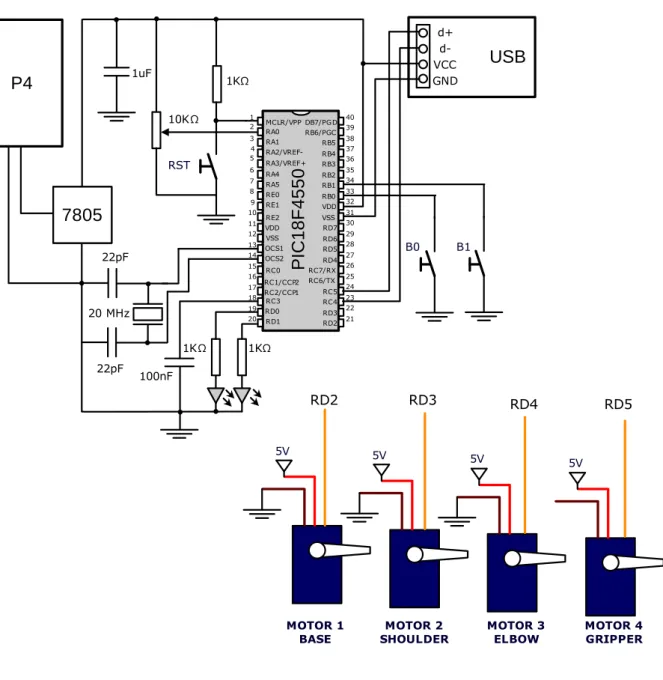
The electronic structure of the robotic arm is built around a PIC18F4550 microcontroller to perform desired robotic arm movements. This microcontroller complies with the criteria of flexibility because the program firmware can be easily written through USB connection. The 40 pins allow a rich set of devices might be connected like sensors and actuators for a wide range of handling applications.
The electronic circuit is shown in Figure 2. The pins RD2, RD3, RD4 e RD5 are used to control the base, shoulder, elbow and gripper, respectively. This is connected with a PC through a serial
Braz. J. of Develop., Curitiba, v. 5, n. 7, p. 10528-10540 jul. 2019 ISSN 2525-8761 communication standard RS-232 or USB communication. The main electronic circuit is shown below in Figure 2. USB MCLR/VPP RA0 RA1 RA2/VREF-RA3/VREF+ RA4 RA5 RE0 RE1 RE2 VDD VSS OCS1 OCS2 RC0 RC1/CCP2 RC2/CCP1 RC3 RD0 RD1 DB7/PGD RB6/PGC RB5 RB4 RB3 RB2 RB1 RB0 VDD VSS RD7 RD6 RD5 RD4 RC7/RX RC6/TX RC5 RC4 RD3 RD2 P IC 1 8 F 4 5 5 0 1 2 3 4 5 6 7 8 9 10 11 12 13 14 15 16 17 18 19 20 40 39 38 37 36 35 34 33 32 31 30 29 28 27 26 25 24 23 22 21 20 MHz 22pF 22pF GND VCC d+ d-100nF RST 1uF 10KΩ P4 7805 7805 B0 B1 1KΩ 1KΩ 1KΩ MOTOR 1 BASE 5V MOTOR 2 SHOULDER 5V MOTOR 3 ELBOW 5V MOTOR 4 GRIPPER 5V RD2 RD3 RD4 RD5
Figure 2. Main electronic circuit.
2.3 SOFTWARE
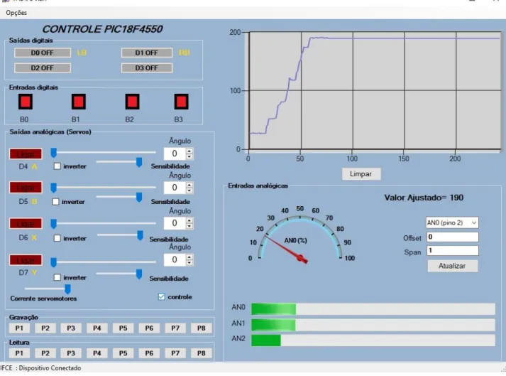
The first version of this project has been developed in VisualTM C# interface. This interface can control over USB communication four servomotors, four digital inputs pins and four digital output pins. Furthermore, the operator can get even more accurate movements using an Xbox one controller
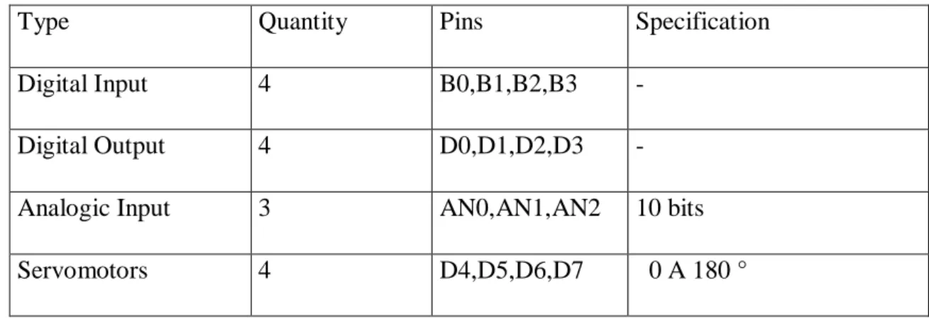
Braz. J. of Develop., Curitiba, v. 5, n. 7, p. 10528-10540 jul. 2019 ISSN 2525-8761 joystick. The joystick is connected with a computer through a USB interface and computer can control vast majority pins of the microcontroller PIC18F4550 according to the Table 2.
Table 2. Specification of commands over USB communication.
Type Quantity Pins Specification
Digital Input 4 B0,B1,B2,B3 -
Digital Output 4 D0,D1,D2,D3 -
Analogic Input 3 AN0,AN1,AN2 10 bits
Servomotors 4 D4,D5,D6,D7 0 A 180 °
Braz. J. of Develop., Curitiba, v. 5, n. 7, p. 10528-10540 jul. 2019 ISSN 2525-8761
Figure 3. Visual C# interface controlling the microcontroller PIC18F4550.
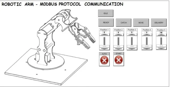
The second version has been developed to facilitate the programming activities. The module of the microcontroller is connected to the supervisory via the industrial modbus protocol. In this network, only one transceiver may transmit data at a time by polling technique. The supervisory is defined as the “master” node that talks to each of the agents subsequently to let it send one message, while each agent is listening to all messages and can filter out only those messages that apply to it (Thomas,2008).The poses (robotic arm positions) have been pre-determinated in SCADA software (Elipse, 2019). The main poses include: ready, catch, move and delivery. An auto button commands the robotic arm to pick/place objects automatically. The main screen is shown in Figure 4.
Braz. J. of Develop., Curitiba, v. 5, n. 7, p. 10528-10540 jul. 2019 ISSN 2525-8761 Figure 4. Supervisory based on Elipse TM SCADA software.
3 MANIPULATOR KINEMATICS
In essence, the implementation of the kinematics model can expand to a development of a multi-disciplinary technical system whereas students’ teams can apply this in the design of robotic arms. The standard Denavit-Hartenberg (D-H) is being taking and D-H parameters are shown in Table 2:
Table 2. D-H table for the Figure 1
Frame(i) 𝑎𝑖 αi 𝑑𝑖 𝜃𝑖
1 0 90º 𝑙1 𝜃1
2 𝑙2 0 0 𝜃2
3 𝑙3 0 0 𝜃3
Where 𝑙1 = 12,75, 𝑙2 = 7,25𝑐𝑚 and 𝑙3 = 6𝑐𝑚 refers to robot dimension. Now, we can find the forward transformation matrices 𝑖−1𝑖𝑇 from frame i to frame i − 1 for standard DH method is given by:
Braz. J. of Develop., Curitiba, v. 5, n. 7, p. 10528-10540 jul. 2019 ISSN 2525-8761 𝑇
𝑖 𝑖−1 = [
cos θ𝑖𝑠𝑖𝑛 α𝑖 − sin α𝑖. cos α𝑖 sin θ𝑖. sin α𝑖 α𝑖cos θ𝑖 sin θ𝑖 cos θ𝑖. cos α𝑖 − cos θ𝑖. sin α𝑖 α𝑖sin θ𝑖
0 sin α𝑖 cos α𝑖 𝑑𝑖
0 0 0 1
] (1)
And the complete transformation 30Tis found from:
30𝑇= 𝑇10 21𝑇 𝑇32 (2)
After obtaining 03T, we will add the end-effector to get the final global coordinates:
[ Δ 𝑥 Δ 𝑦 Δ 𝑧 1 ] = T30 [ 1 0 0 l4 0 1 0 0 0 0 1 0 0 0 0 1 ] [ 0 0 0 1 ] (3)
where Δx, Δy and Δz are the variation on each axis, and 𝑙4 = 7𝑐𝑚 is the end-effector dimension.
4 EXPERIMENT RESULTS AND DISCUSSION
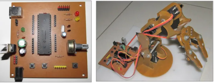
In order to prove the robot system´s effectiveness, many industrial simulations were made. For instance, it has been built an automated transportation of materials between a conveyors section and a storage bins to realize an integrated material handling system. Furthermore, through simulation in the SCADA software the user can estimate optimum D-H parameters in constructing new control solution. The figure 5 shows circuit board and the robotic arm.
(a) (b)
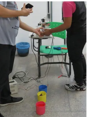
Braz. J. of Develop., Curitiba, v. 5, n. 7, p. 10528-10540 jul. 2019 ISSN 2525-8761 Furthermore, the engineering students can create a new wave of robotic tools that may become widespread in basic education (Bassily et al 2007). For instance, a robotic launch contest has been developed to spread selective collection concepts such as where to dispose the trash. In this case, a student can win the game if the robot hitting the correct trash can target. For instance, blue can for paper trash, red can for plastic trash and yellow can for metal trash. The launch contest is shown in Figure 6.
Figure 6 - A robotic launch contest spreading selective collection concepts
5 CONCLUSIONS
It is proven that robotic arm using a SCADA software via modbus serial communication is an excellent educational platform that enables students to address a wide range of engineering fields. In fact, in many ways, it goes beyond the traditional simulation software, improving skills in many disciplines such as electronics, mechanics, signal processing and automatic control. The formation teams of engineers can solve a real industrial problem by using a prototype robotic arm, empowering the students to take ownership of the fundamental industrial concepts of programming and designing of robots.
Braz. J. of Develop., Curitiba, v. 5, n. 7, p. 10528-10540 jul. 2019 ISSN 2525-8761 Moreover, this project can emphasize the interdisciplinary in basic education helping students to apply learning strategies by using robotic arms. In this case, the students can quickly learn how to incorporate robots and mechatronic systems in physics, mathematics, programming and environment education. For instance, in environmental education, a robotic launch contest has been developed to spread selective collection concepts teaching where to dispose the trash
Braz. J. of Develop., Curitiba, v. 5, n. 7, p. 10528-10540 jul. 2019 ISSN 2525-8761
REFERENCES
BALCH,T.,SUMMET,J.,BLANK,D.,KUMAR,D.,GUZDIAL,M.,O'HARA,K.,WALKER,D.,SWEAT,M., GUPTA, G., TANSLEY, S. ET AL., “DESIGNING PERSONAL ROBOTS FOR EDUCATION: HARDWARE SOFTWARE AND CURRICULUM”,IEEEPERVASIVE COMPUTING, VOL.7, NO.2, PP.5-9,2008.
BRÄUNL,THOMAS,2008.EMBEDDED ROBOTICS:MOBILE DESIGN AND APPLICATION WITH EMBEDDED
SYSTEMS.SPRINGER,BERLIN 3RD EDITION.
ELIPSE “ELIPSE SOFTWARE” ELIPSE SOFTWARE COMPANY. MAR. 2019 <
HTTPS://WWW.ELIPSE.COM.BR/DOWNLOADS/>
BASSILY,H.,SEKHON,R.,BUTTS,D.E.,WAGNER,J,“A MECHATRONICS EDUCATIONAL LABORATORY –
PROGRAMMABLE LOGIC CONTROLLERS AND MATERIAL HANDLING EXPERIMENTS”, MECHATRONICS,
VOL.17, PP.480-488
HAO, W.G., LECK Y, HUN, L., 2011. “6-DOF PC-BASED ROBOTIC ARM (PC-ROBOARM) WITH EFFICIENT TRAJECTORY PLANNING AND SPEED CONTROL”. IN 4TH INTERNATIONAL CONFERENCE ON
MECHATRONICS (ICOM),17-19MAY 2011,KUALA LUMPUR,MALAYSIA.
MONDADA, F., BONANI, M., RAEMY, X., PUGH, J., CIANCI, C., KLAPTOCZ, A., MAGNENAT1, S., ZUFFEREY, J.C., FLOREANO, D., MARTINOLI A., 2009. “THE E-PUCK, A ROBOT DESIGNED FOR
EDUCATION IN ENGINEERING”. IN
PROCEEDINGS OF THE 9TH CONFERENCEON AUTONOMOUS ROBOT SYSTEMSAND COMPETITIONS, CASTELO BRANCO,PORTUGAL.
MOHAMMED,A.A., AND SUNAR,M.,2015.“KINEMATICS MODELING OF A 4-DOF ROBOTIC ARM”.IN
Braz. J. of Develop., Curitiba, v. 5, n. 7, p. 10528-10540 jul. 2019 ISSN 2525-8761 SOBH, T.M., ABUZNEID, A., MIHALI, R., “A PC-BASED SIMULATOR/CONTROLLER/MONITOR
SOFTWARE FOR A GENERIC 6-DOF MANIPULATOR”, JOURNAL OF INTELLIGENT AND ROBOTIC