UNIVERSIDADE DA BEIRA INTERIOR
Engenharia
General Conceptual Design Problems of a
Parabolic Solar Sail Structure
Filipe Couceiro Potes
Dissertação para obtenção do Grau de Mestre em
Engenharia Aeronáutica
(Ciclo de estudos integrado)
Orientador: Prof. Doutor José Miguel Almeida da Silva
Co-orientador: Prof. Doutor Pedro Vieira Gamboa
v
Acknowledgments
The realization of this thesis would not have been possible without the invaluable contribution of several people to whom I wish to express my sincere gratitude.
To Dr. José Miguel Silva, my supervisor, for his unfailing and constant attention, support and encouragement which always kept me motivated throughout all the investigation.
To Dr. Pedro Gamboa, my co-supervisor, for his readiness, suggestions and great dedication that was undoubtedly crucial for the completion of this work.
I am also grateful to Dr. Anna Guerman for her valuable knowledge as well as her important advice during the work period.
Lastly, to Benjamin Schneuwly who played an important role in the early stages of the research, namely during the experimental tests conducted in Chapter 3, for his availability and willingness to help in some of the most difficult phases.
Finally I would like to dedicate this thesis to my relatives and close friends, in particular to my parents and grandparents for their encouragement and for always having believed in me. If it was not for their support, I am sure I would not be where I am today.
ix
Abstract
Solar sails represent a promising and practicable solution for future long-duration space missions involving deep space travel. Since their source of propulsive thrust derives from the energy exerted by solar radiation pressure, they do not depend on any on-board propellant, which thus minimizes energy consumption during a mission and consequently its final costs. However, because in Earth´s vicinity solar pressure presents a very low intensity, and in order to provide the necessary amount of thrust this type of solar-powered spacecraft typically requires an enormous surface area whilst at the same time maintaining the lowest possible mass. Such requirements oblige the adoption of very large structures usually consisting of ultra-thin membranes supported by long slender booms, in the order of tens of meters. This causes some difficulties on the structural design process since the deployment and maneuvering capabilities have to be optimized without compromising the mechanical performance of the whole solar vehicle.
Among the various types of solar sail structural configurations, there is a very ambitious concept considered to be highly efficient, which consists on the parabolic solar sail. In this type of solar-propelled spacecraft, a small mirror designated as the director reflects the sunlight collected from a larger parabolic structure which in turn remains constantly oriented towards the incoming direction of the sunbeams so as to always guarantee the maximum available thrust. Since in this case maneuverability is achieved exclusively by tilting the director component, this allows the entire structure to operate without having to change its inclination in relation to the Sun.
The scope of this work is to explore different possibilities for the conceptual design of a parabolic space structure intended to act as a solar sail collector, with special emphasis on the parabolic shape maintenance issue, since this is crucial for the maximization of the sunlight concentration into its focal point, as well as on its overall structural behavior. On a first approach, a structure which consists solely of an initially flat circular membrane simply supported around its perimeter and without any type of load supporting elements along its radials is considered. In this case, the possibility for the structure to make use of the solar pressure itself as a form of obtaining the desired parabolic curvature is investigated. Assuming the membrane as a perfectly reflecting surface, a parametric study is conducted in order to determine several parameters of interest, as a function of its radius size and thickness. Although the resulting deformed shapes prove to be very similar to parabolic ones, since the obtained focal distances are considerably high, this structural concept does not become feasible for solar sail applications. Consequently, a parabolic boom-based type of structural configuration resembling an open umbrella is considered afterwards. Here, the booms are responsible for guaranteeing the membrane´s parabolic curvature therefore
x
enabling the focal distance to be initially established during the design phase of the structure. In order to assess its behavior due to solar pressure action, a parametric study is performed to investigate the effects of several design features such as the collector radius, membrane thickness, number of booms, number of supporting points of the membrane along the booms, as well as the effect of a possible angular velocity around the structure´s symmetry axis, with regard to the impact that these have on the resulting loadings and maximum deformations of the entire structure. In the end, the structure´s natural frequencies and mode shapes are also determined.
The obtained results are of upmost importance to the design of an optimized structure which provides greater efficiency in terms of control thrust of the vehicle, thus forming the basis for further more detailed structural and orbital control analysis of this solar propelled parabolic sail spacecraft.
Keywords: Solar sail; Space structures; Parabolic collector; Solar pressure; Circular
membrane; Focal distance; Light spot
xiii
Resumo
As velas solares representam uma solução promissora e viável para as futuras missões espaciais de longa duração envolvendo viagens no espaço profundo. Uma vez que a sua fonte de impulsão propulsiva advém da energia exercida pela pressão da radiação solar, estas não dependem de nenhum propelente a bordo, o que minimiza assim o consumo energético durante uma missão e consequentemente os seus custos finais. No entanto, devido à pressão solar apresentar uma intensidade muito baixa na vizinhança da Terra, e de modo a fornecer a quantidade necessária de impulso, este tipo de veículo espacial tipicamente requer uma enorme área de superficie, mantendo ao mesmo tempo a massa no valor mais baixo possível. Tais requisitos obrigam à adoção de estruturas de enormes dimensões normalmente constituidas por membranas ultra-finas suportadas por longos booms, na ordem das dezenas de metros. Isto causa algumas dificuldades no processo do design estrutural, uma vez que a implantação e capacidades de manobra têm de ser otimizadas sem comprometer o desempenho mecânico de todo o veículo solar.
Entre os vários tipos de configurações estruturais de velas solares, existe um conceito muito ambicioso considerado altamente eficiente, que consiste na vela solar parabólica. Neste tipo de veiculo espacial propulsionado pelo sol, um pequeno espelho designado como diretor reflete a luz solar coletada a partir de uma estrutura parabólica maior que por sua vez, permance constantemente orientanda na direção dos raios solares incidentes de modo a garantir sempre o máximo impulso disponível. Uma vez que neste caso a capacidade de manobra é obtida exclusivamente pela inclinação do componente do diretor, tal permite que toda a estrutura opere sem ter de alterar a sua inclinação em relação ao Sol.
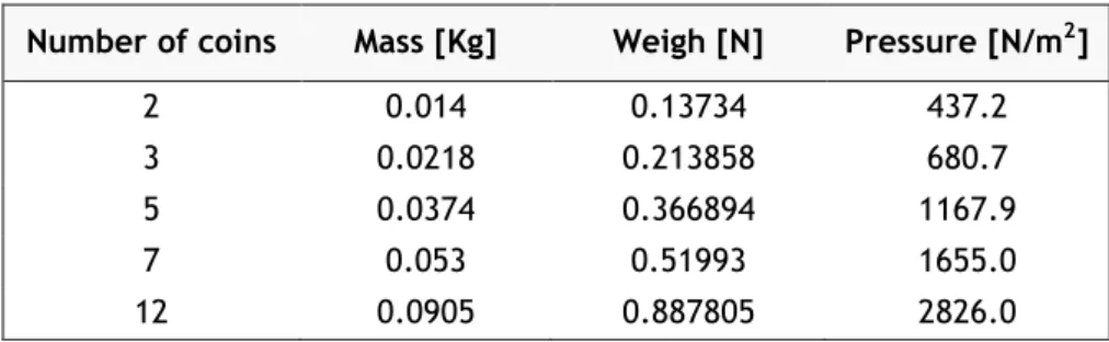
O âmbito deste trabalho consiste em explorar diferentes possibilidades para o projeto conceitual de uma estrutura espacial parabólica destinada a atuar como um coletor de uma vela solar, com especial ênfase na questão da manutenção de uma forma parabólica, uma vez que esta é crucial para a maximização da concentração da luz solar no seu ponto focal, bem como o seu comportamento estrutural global. Numa primeira abordagem, uma estrutura que consiste unicamente numa membrana circular inicialmente plana, simplesmente suportada em torno do seu perimetro, e sem qualquer tipo de elementos de suporte de carga ao longo das suas radiais, é considerada. Neste caso, a possibilidade da estrutura fazer uso próprio da pressão solar como forma de obter a curvatura parabólica desejada é investigada. Assumindo a membrana como uma superficie perfeitamente refletora, procede-se à realização de um estudo paramétrico de modo a determinar diversos parâmetros de interesse, em função do seu tamanho do raio e espessura. Apesar das deformações resultantes provarem ser muito similares a formas parabólicas, uma vez que as distâncias focais obtidas são consideravelmente elevadas, este conceito estrutural não se torna viável para aplicações em
xiv
velas solares. Consequentemente, um tipo de configuração estrutural parabólica baseada em
booms semelhante a um guarda-chuva aberto é considerada numa etapa posterior do
trabalho. Aqui, os booms são responsáveis por garantir a curvatura parabólica da membrana permitindo assim que a distância focal seja inicialmente estabelecida durante a fase de concepção da estrutura. A fim de avaliar o seu comportamento devido à acção da pressão solar, um estudo paramétrico é efetuado com o intuito de investigar os efeitos de várias caracteristicas de projeto, tais como o raio do colector, espessura das membranas, número de booms, número de apoios entre as membranas e os booms, assim como o efeito de uma possivel velocidade angular em torno do eixo de simetria da estrutura, no que respeita ao impacto que estes têm sobre as cargas resultantes e deformações máximas de toda a estrutura. No final, as frequências naturais e modos de vibração da estrutura são também determinados.
Os resultados obtidos são de extrema importância para a concepção de uma estrutura otimizada que proporcione grande eficiência em termos de controlo de impulso do veículo, formando assim a base para análises estruturais e de controlo orbital mais pormenorizadas deste veiculo solar parabólico propulsionado pelo Sol.
Palavras-chave: Vela solar; Estruturas espaciais; Coletor parabólico; Pressão solar;
xvii
Contents
Acknowledgments... v Abstract ... ix Resumo ... xiii Contents ... xviiList of Figures ... xxi
List of Tables ...xxv Nomenclature ... xxix Chapter 1 – Introduction ... 1 1.1 Motivation ... 1 1.2 Objectives ... 4 1.3 Literature review ... 6 1.3.1 Historical perspective ... 6 1.3.2 Technological developments ... 7
1.3.3 Researches based on finite element analysis ... 11
Chapter 2 – Theoretical background ... 19
2.1 Solar radiation pressure physics ... 19
2.2 Forces on a perfectly reflecting solar sail... 21
2.3 Analytical solution for a circular membrane under uniform transverse load ... 23
2.4 Approximate focal distance of a circular membrane ... 26
Chapter 3 – Initial studies with membrane-based components ... 27
3.1 ABAQUS® shell and membrane elements formulation ... 27
3.2 Square membrane under uniform pressure ... 28
3.2.1 Numerical model description ... 28
3.2.2 Results and discussion ... 29
3.3 Rectangular membrane under concentrated load ... 31
3.3.1 Experimental setup ... 31
3.3.2 Numerical model description ... 32
3.3.3 Results and discussion ... 33
Chapter 4 – Flat circular membrane under solar pressure ... 35
4.1 Numerical model formulation ... 35
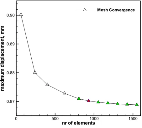
4.1.1 Mesh convergence study ... 37
4.1.2 Solar pressure loading conditions ... 38
4.2 Results and discussion ... 39
4.2.1 Nodal displacements ... 41
4.2.2 Parabolic approximations ... 42
4.2.3 Focal distances ... 44
xviii
Chapter 5 – Boom-based parabolic solar collector ... 49
5.1 Numerical model formulation ... 49
5.2 Parametric studies ... 51
5.2.1 Boom number ... 51
5.2.2 Connecting points ... 54
5.2.3 Solar collector size ... 55
5.2.4 Solar collector membrane thickness ... 56
5.2.5 Angular velocity effect ... 57
5.2.6 Membrane geometry ... 59
5.3 Natural frequencies and mode shapes ... 60
Chapter 6 – Conclusions and future work ... 65
6.1 Final conclusions ... 65
6.2 Prospects for future developments ... 66
References ... 69
Annex A – MATHEMATICA® analytical theorem for circular membrane ... 73
Annex B – Mylar® samples mid-point displacement plots ... 77
Annex C – MATLAB® solar pressure iterative calculation code ... 79
Annex D – Non-dimensional displacements for varying membrane thickness ... 83
xxi
List of Figures
Figure 1 - Solar Sail propeled by solar radiation the same way wind pushes a sailing ship [1]. . 1
Figure 2 - SSPT structural configuration [4]. ... 3
Figure 3 - DR SPT structural configuration [4]. ... 3
Figure 4 - An artist´s concept of Znamya 2 [8]. ... 7
Figure 5 - DLR´s solar sail prototype [10]. ... 7
Figure 6 - CFRP deployable boom used by DLR [8]. ... 8
Figure 7 - DLR´s solar sail deployment module [11]. ... 8
Figure 8 - Kapton® substrate sample [12]. ... 8
Figure 9 - Sheet of reflecting Mylar® [13]. ... 8
Figure 10 - Sketch of the Cosmos 1 [8]. ... 9
Figure 11 - Solar Sail IKAROS [15]. ... 9
Figure 12 - IKAROS configuration [16]. ... 10
Figure 13 - IKAROS deployment stages [15]. ... 10
Figure 14 - Two square solar sail design concepts used in reference [17]. ... 11
Figure 15 - Deflections after solar pressure and thermal load have been applied [18]. ... 12
Figure 16 - Static test on solar sail membrane experimental model [19]. ... 12
Figure 17 - Wrinkled shape obtained for the two more heavily loaded corners case [20]. ... 13
Figure 18 - Prototype of CRTS offset reflector [22]. ... 15
Figure 19 - Experimental model used [24]. ... 16
Figure 20 – 0.3 meter reflector antenna dish [25]. ... 16
Figure 21 – Displacement patterns for 0.3m numerical model [25]. ... 17
Figure 22 – Forces on an idealized surface element. ... 21
Figure 23 – Geometric focal distance and light spot radius determination ... 26
Figure 24 - General shell/membrane elements with respective faces [27]. ... 27
Figure 25 – 20 cm side square membrane with loads and boundary conditions. ... 29
Figure 26 - Deformation field obtained for the numerical model. ... 30
Figure 27 - Experimental setup to pre-tension the membrane [30]. ... 31
Figure 28 - Displacement measurement with a laser sensor device [30]. ... 32
Figure 29 - Mesh and deformation field verified for the numerical model. ... 33
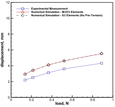
Figure 30 – Experimental and numerical results of mid-point displacements verified for Mylar® 850 of 20µm film. ... 34
Figure 31 – Numerical model with respective boundary condition. ... 36
Figure 32 - Stiffness for initially flat and for deformed membrane [31]. ... 36
Figure 33 - Mesh convergence study results with S4 elements. ... 37
Figure 34 - Mesh adopted for the numerical model. ... 38
xxii
Figure 36 – Final solution for the 1m radius/1µm thickness membrane supplied by MATLAB®. 39
Figure 37 – Numerical analysis process scheme during the parametric study. ... 40 Figure 38 – Circular membrane deformation field under non-uniform pressure load. ... 40 Figure 39 – Non-dimensional displacement variation for the 1µm thickness membranes... 41 Figure 40 – Middle point displacement variation with membrane radius R and thickness t. ... 42 Figure 41 - 25m radius/1µm thickness membrane deflection and respective parabolic fit. ... 43 Figure 42 - Focal distance variation with membrane radius R and thickness t. ... 45 Figure 43 – Light spot radius variation with membrane radius R and thickness t. ... 46 Figure 44 – Numerical model example under solar pressure loading conditions. ... 50 Figure 45 – Mast and booms mesh. ... 51 Figure 46 – Membrane gore sweep mesh. ... 51 Figure 47 – Boom tip deflection with increasing number of booms. ... 52 Figure 48 – Deformation field for the baseline collector case. ... 53 Figure 49 – Five-boom Von Mises stress distribution. ... 53 Figure 50 – Eight-boom Von Mises stress distribution. ... 53 Figure 51 – Boom and membrane maximum deformations with increasing supporting points. 54 Figure 52 – Seventeen-point connected Von Mises stress distribution. ... 55 Figure 53 – Continuously connected Von Mises stress distribution. ... 55 Figure 54 - Boom and membrane maximum deformations with increasing radius size. ... 56 Figure 55 – Membrane maximum deformations with increasing thickness. ... 57 Figure 56 - Deformation field for collector under 0.044 rad/s angular velocity. ... 57 Figure 57 – Von Misses stresses over membrane gore under 0.044 rad/s angular velocity. .... 58 Figure 58 - Deformation field for collector under 0.049 rad/s angular velocity. ... 58 Figure 59 - Deformation field for the collector with new membrane approach. ... 59 Figure 60 - Von Misses stresses over triangle-shaped membrane gore. ... 59 Figure 61 – Numerical model´s central hub with respective boundary condition. ... 60 Figure 62 – Example of the mesh adopted for a 14 meter length parabolic boom. ... 62 Figure 63 - Mode shapes for 18m collector booms with 0º/90º fibre sequence. ... 62 Figure 64 - Mode shapes for 18m collector booms with 45º/-45ºfibre sequence. ... 62 Figure 65 – Natural frequency variation as a function of boom length. ... 63 Figure B.1 – Experimental and numerical results of mid-point displacements verified for
Non-specified type of Mylar® of 5µm film ... 77 Figure B.2 – Experimental and numerical results of mid-point displacements verified for
Mylar® OL 140L of 13µm film. ... 77 Figure D.1 – Non-dimensional displacement variation for the 2µm thickness membranes... .. 83 Figure D.2 – Non-dimensional displacement variation for the 5µm thickness membranes... .. 83 Figure D.3 – Non-dimensional displacement variation for the 8µm thickness membranes... .. 84
xxv
List of Tables
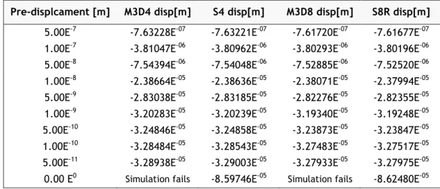
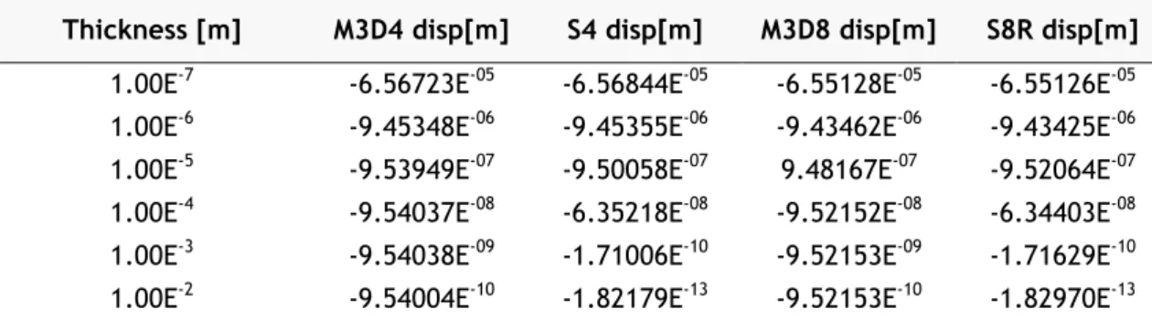
Table 1 - Middle-point deformations considering different membrane and homogeneous shell elements for different pre-displacement magnitudes. ... 29 Table 2 - Middle-point deformations considering different membrane and homogeneous shell
elements for different thickness values. ... 30 Table 3 - Pressure magnitudes as a function of growing number of coins. ... 32 Table 4 – Parabolic fit absolute mean percentage errors. ... 44 Table 5 – Parabolic collector´s baseline dimensions and material properties. ... 51 Table 6 - Standard CFRP material properties for 0º/90º stacking [32]. ... 61
xxix
Nomenclature
Energy of a moving body or Material´s Young modulus Body´s rest mass
Speed of light
Photon´s momentum magnitude Planck´s constant
Photon´s frequency or Material´s Poisson ratio Energy flux across a surface
Energy flux measured at Earth´s distance from the Sun Sun-Earth distance
Radial coordinate Solar luminosity
Energy transported across a surface Area of given element surface
Period of time
Momentum exchange across a surface Pressure exerted on a surface
Force due to incident radiation Surface attitude angle
Incident radiation direction Force due to reflected radiation Reflected radiation direction Vector normal to surface element
Force exerted on idealized solar sail surface
Characteristic value of solar pressure in the vicinity of the Earth Transverse displacement
Maximum transverse displacement Radius of circular membrane
xxx
Radial displacement at radius First integration constant Second integration constant Radial strain
Transverse strain
Strain energy of membrane Work done
Potential energy of an elastic body Thickness of membrane
Parabolic function Focal distance
Slope of the function at nodes
Minimized radius spot size
Mean percentage error Real deformed coordinate Parabolic deformed coordinate Light spot radius
Chapter 1- Introduction
1
Chapter 1 – Introduction
1.1 Motivation
Solar sails consist of spacecraft that use the energy supplied by solar radiation as a direct means of locomotion through space in the same way a sailing ship uses winds in our planet (Figure 1). This is effectively possible, since sunlight is composed of a quantity of energy known as photons that act like atomic particles. When these quantum packets of energy are intercepted by the solar sail surface, they impart their momentum to the sail film through two distinct processes, firstly by the initial incidence, and again by reflecting back from it. The force caused by the momentum exchange which results from the combination of both processes is therefore responsible for generating an impulse on the entire structure [1].
Figure 1 - Solar Sail propeled by solar radiation the same way wind pushes a sailing ship [1].
This unique and elegant form of propulsion is significantly advantageous, since contrary to conventional propulsive systems such as rocket engines driven by chemical reactions, solar sails are not limited by an exhaustible energy source, which offers then the added benefit of new mission opportunities at the same time with a much lower monetary cost. Furthermore, as sunlight is permanent, solar sails are also submitted to a constant acceleration limited only by the lifetime of the sail materials in the space environment. Even though this acceleration may be very little at first, this will enable them in a relatively short time to reach very high speeds, far greater than some of those verified with conventional rocket launched craft. Since at the Earth´s distance from the Sun, i.e. 1 A.U., the momentum carried by the photons is extremely small, solar sails must present a very large surface area while at the same time maintaining the lowest mass as possible. Only so, it is possible to generate a relatively high acceleration from the momentum transported by the largest number of intercepted photons.
Chapter 1- Introduction
2
Consequently, the structure of this type of spacecraft is generally composed of very large membranes, consisting of highly reflective ultra-thin films such as of Kapton® or Mylar®, which
are held in tension by the application of a force field on its edges. These forces can be generated either mechanically from some sort of support structure, namely by long slender booms, or by centrifugal forces induced by the spinning motion of the whole solar sail structure [2].
There are three types of solar sails structural configurations most commonly under discussion namely the three-axis stabilised (flat square sail), the spin-stabilised heliogyro sail and the spin-stabilised disc sail. Nevertheless, despite the great set of advantages that these may present, there is also another very promising solution capable of offering potentially superior performance in terms of acceleration and controllability which is to adopt a parabolic solar sail, also commonly referred to as the compound spacecraft. Although the concept may appear to be relatively recent, it is believed that its preliminary ideas were first discussed in Soviet literature some time ago, namely by Tsander back in the 1970s. More recently, it was studied and subsequently re-invented by some other authors, among which the physicist Robert Forward in the 1990s who coined the term “Solar Photon Thrustor” [3].
When it comes to the more conventional approaches regarding solar sail configurations, one should note that the photons are collected and reflected by the same sheet of material, i.e. the light collector and reflector represent the same structure. As a result, if the desired thrust direction is not directly away from the sun then the sail has to be tilted at some angle with respect to the incoming sunlight direction. This results in a loss of propulsive efficiency of the sail, since as it is tilted the effective photon collecting area is reduced. However, as in a parabolic solar sail the functions of collecting and directing the solar radiation are separated, this trend will not be verified.
Generally speaking, the parabolic solar sail is composed of a large reflecting surface (similar in size and mass to that of a conventional solar sail) known as the collector that directs the incoming solar radiation into a system of much smaller reflecting mirrors which in turn can be subdivided in two different arrangements [4] according to the number of mirrors: consisting solely by a director - the SSPT (Single Solar Photon Thrustor) shown in Figure 2, or by of a reflector and a director - the DR SPT (Double Reflector Solar Photon Thrustor) presented in Figure 3. In either case, the collector is designed to be always in a sun-facing attitude so as to ensure the maximum area of sunlight exposure, which means that this type of solar sail configuration will always have a superior performance in terms of maximum propulsive thrust. The director, which consists of a small flat mirror that can be tilted at a determined angle, reflects the incoming light rays coming from the collector on a specific desired orientation, hence, the responsibility of defining the thrust vector and consequently controlling the motion of the spacecraft, is attributed to this component. However, in order to accurately
Chapter 1- Introduction
3 focus all the incoming sunlight into the director (or reflector depending on the type of arrangement considered) it becomes understandable that the collector necessarily has to present a parabolic surface. Only then, it is possible to concentrate the sunlight onto a specific point of the space environment designated by the focal point, which should coincide with the director´s (reflector´s) position. It is evident that the accurate maintenance of the collector´s parabolic geometric shape becomes therefore an issue of paramount importance, since it is mandatory for the maximization of the available thrust of the whole spacecraft. Despite the fact that the parabolic solar sail may present a significant mass penalty in contrast to the standard flat solar sail configurations, it has the added benefit of providing a potentially superior performance in terms of maximum propulsive thrust, a less complex control system (the entire spacecraft does not need to be rotated thus not compromising as much its structural integrity) as well as a maximum capacity for useful load. All these advantages make this solar sail concept particularly attractive.
Figure 2 - SSPT structural configuration [4].
Chapter 1- Introduction
4
1.2 Objectives
The present thesis is subdivided in three main distinct parts, all of which are essentially based on a set of numerical simulations carried out using the finite element code ABAQUS® v6.11-3.
In the first section, some initial studies are performed in order to gain further insight into the proper modelling of membrane elements by resorting to the finite element method. The goal is to understand how the maximum deformations of the membranes vary according to different material properties, section definition types as well as boundary conditions. Additionally, experimental measurement tests are also conducted in the chapter´s last part, so as to validate some of the results obtained during the numerical simulations.
The second part aims at assessing the feasibility of creating a parabolic solar sail collector, whose structural concept is characterized only by an initially flat circular membrane translationally constrained around its perimeter and without any type of load supporting elements along its radials. In particular, it is intended to explore and to validate the hypothesis of the membrane in making use of solar pressure as a means of obtaining the required parabolic curvature, once this would greatly simplify and lighten the structure of the spacecraft, therefore having considerable advantages when compared for example to a boom--based type of structural configuration. With this objective in mind, a parametric study is performed to determine some crucial parameters of interest, namely the resulting approximate focal distances together with the respective light spot diameters on the focal plane, taking into consideration the variation of both the radius size and thickness of the membrane. In order to do so, the nodal displacement profiles along the membrane´s radials need to be first computed for each case. During the analyses, an analytical method capable of determining the mid-point maximum displacements together with the focal distance for a perfect parabolic surface is also presented as an additional tool for results correlation. Differently to the previous studies which are mainly focused on the behaviour of membrane based structural parts in space environment, the last part takes in consideration the adoption of a parabolic collector design constituted by several booms and membrane gores as well as a small mast in the middle, thus resembling an open umbrella type of structural configuration. In this case, since the parabolic shape is ensured by the curvature provided by the stiffness of the booms, the structure´s focal distance may be featured as an initially known variable, once this is defined during the design phase. The objective of this study consists on evaluating the influence of several design parameters with regard to the impact that these have on the resulting loadings and maximum deformations of the entire structure when under the effect of solar pressure. These include varying the collector radius size, membrane thickness, number of booms, number of supporting points of the membrane along the booms, as well as to take into consideration the effect of a possible angular velocity around the structure´s
Chapter 1- Introduction
5 symmetry axis. A different geometrical concept for the membrane gores is also addressed. Ultimately, the collector´s natural frequencies and the respective mode shapes are also extracted in order to characterize its dynamic response.
Chapter 1- Introduction
6
1.3 Literature review
1.3.1 Historical perspective
Although only relatively recently solar sails have reaffirmed themselves as an innovative and practical mean of spacecraft propulsion, its concept has already a long and vast history, dating back to the Soviet pioneers, and probably even before that.
It all first started back in 1873 when the Scottish physicist James Maxwell predicted the existence of radiation pressure as a consequence of his unified theory of electromagnetic radiation [5]. The first experimental results of his theory were then demonstrated by the Russian physicist Peter Lebedew in 1900 at the University of Moscow. Between this period some French authors, notably Faure and Graffigny wrote about spaceships propelled by mirrors, however, it was not until the beginning of the 20th century that the concept of a
solar sail was more accurately established as an engineering principle. The credit of such principle is attributed to the Latvian engineer Fridrickh Tsander considered the first to write about solar sailing practicability in 1924. It is thought though, that his ideas had been in part inspired by Tsiolkovsky, considered the Soviet father of astronautics, who had already written before in 1920 about the potential use of space propulsion using light.
Following the initial development work by Tsander and Tsiolkovsky, the concept of solar sail took approximately thirty years to be re-invented and published in literature. It was only in 1951 that the American aeronautical engineer Car Wiley explored the fundamental benefits of solar sails for a range of mission applications comparatively to chemical propulsion systems. Subsequently in 1958, Richard Garwin authored the first solar sail paper in the Journal Jet
Propulsion where he coined the term “solar sailing”. He recognized, for instance, the
potential advantages of solar sails to reach very high velocities over a relatively short period, since these would be continuously accelerated. After Garwin´s standpoint about solar sailing, several studies regarding solar sails orbits and trajectories, were undertaken during the period between the late 1950s and early 1960s.
Yet, it was not until the early 1970s, which coincided with development of the Space Shuttle, in addition to technological advances with deployable space structures as well as thin films, that a solar sail could probably find a practical application for a specific mission. By 1973 NASA considered the use of solar sails as a potential propulsion system for performing a rendezvous mission with Halley’s Comet during its 1986 flyby of earth [6]. However, the required level of solar sail performance for this specific mission suggests that the study might have been considered too optimistic given the immature technology of the time in this area.
Chapter 1- Introduction
7
1.3.2 Technological developments
Following Halley’s Comet first studies with solar sails, it was not until the early 1990s that the concept once again regained its technological interest, although to this day, practical experiences with solar sails are still very limited.
In 1993 the Russians were the first to successfully deploy a spinning solar sail-like structure in space. The sail in question called Znamya 2 (Figure 4) consisted of eight pie-shaped panels fabricated from 5 millimetres thick PETF (a Russian version of Mylar®) film with no supporting
structure [7]. It was deployed from an unmanned spacecraft after it had initially completed its first mission of sending supplies to the Mir space station. Then, after being undocked from the Mir, due to the spinning induced form the spacecraft vehicle containing the sail structure, using the resultant centrifugal acceleration a circular 20 meter diameter sail/reflector was finally unfolded. Although its intended purpose was to demonstrate the capability of space based mirror technologies in providing sunlight from space to arctic regions in Russia, most of the technologies verified for the Znamya 2 were directly applicable to the principles of solar sailing [8]. In 1999, the deployment of a second larger 25 meter diameter reflector Znamya
2.5 failed, due to a mission operations and software error [9].
Figure 4 - An artist´s concept of Znamya 2 [8]. Figure 5 - DLR´s solar sail prototype [10].
Towards the end of 1999, the first ever ground deployment of a solar sail structure was demonstrated in Cologne by DLR (Deutschen Zentrum fur Luft-und Raumfahrt) in collaboration with ESA (European Space Agency). The structure in question was a 20 meter side square solar sail with four deployable booms with a length of 14 meters each (Figure 5). The main objective of this ground-test was to evaluate the storage, but most of all, the deployment capabilities of the booms under simulated zero-g conditions. Due to the significant progress in developing lightweight deployable structures using advanced materials, including carbon fibre reinforced plastics (CFRP´s) which have matured over the past decades these were chosen as the DLR´s solar sail booms materials, since they were able to combine high strength and stiffness with low density at the same time. As it may be seen in Figure 6, the booms consist of two laminated sheets which are bounded at the edges to form a tubular “omega” shape [10]. Therefore, they can be easily pressed flat and stowed around a central
Chapter 1- Introduction
8
payload volume (the deployment module shown in Figure 7) for storage, and uncoil from it during the deployment sequence. Once deployed, the booms resume their original tubular “omega” shape, serving as the points of attachment to the sail material.
Figure 6 - CFRP deployable boom used by DLR [8].
Figure 7 - DLR´s solar sail deployment module [11].
Each sail segment used in the DLR´s experiment consisted of right isosceles triangles fabricated in Mylar® with a thickness of 12 microns coated with aluminium on one side.
However, other film materials were considered for the sail segments including substrates of Kapton® and Teonex® (PEN). The purpose for using different materials was to assess the film´s
handling, processing and to evaluate the material´s behaviour for seaming, folding, as well as for sail deployment [11].
Presently, Kapton® and Mylar®, brand trademarks patented by Dupont (the company that
manufactures these types of polymers), are considered for sure the most suitable materials for solar sail membrane applications due to their extreme low weight and good reflecting properties. Kapton® (Figure 8) presents a good resistance to radiation and it is capable of
maintaining its physical and mechanical properties over a wide range of temperatures. Mylar®
(Figure 9), on the other hand, may also be considered a good candidate essentially due to its low density, which makes it a slightly lighter material in comparison to Kapton®. However, its
main drawback is that it has poor resistance to solar UV radiation, therefore making it unsuitable for very long exposures [2]. For this reason, when it comes to the application in solar sails membranes, this kind of material is typically coated on both its sides.
Chapter 1- Introduction
9 Usually, the surface which is orientated towards the incoming solar light is coated with a highly reflective foil, such as aluminium, in order to promote the reflective characteristics of the material. Thus, a higher degree of acceleration is achievable, once the resulting momentum exchange between the surface and photons can be almost doubled. Consequently, as the absorbed light deposits energy in the sail film, the back side surface must be designated to work as a radiator [1]. This way, the material can be held at a constant temperature so that it does not deteriorate. Even though such materials may be considered to have acceptable properties for the time being, the truth is efforts have been made in order to obtain more durable and lightweight materials in the near future.
Another important milestone in the history of solar sails culminated with the project Cosmos 1 developed by the U.S based Planetary Society together with Russia. Its purpose was to conduct the first mission of a solar sail flight. Once in orbit, the structure (Figure 10) would have been deployed through the use of inflatable booms forming a set of 8 triangular blades resembling a heliogyro solar sail configuration. Each of the triangular blades, made of aluminized Mylar® with 5 micron of thickness, would have the ability to be rotated in order to
alter the direction of the thrust vector, therefore allowing the entire structure to be controlled in orbit. However, the Russian rocket carrying it, a converted submarine-launched ballistic missile, failed to separate from the third stage of the rocket, and as a result the sails and the re-entry capsule failed to deploy. If it had been successful, it would have probably been the first solar sail to actually fly in space.
Figure 10 - Sketch of the Cosmos 1 [8]. Figure 11 - Solar Sail IKAROS [15].
Despite all the growing research over the last years on this topic, the merit for the world´s first actual solar sail to successfully deploy on an interplanetary orbit goes to the Japanese. The solar sail in question (Figure 11) called “IKAROS” (Interplanetary Kite-craft Accelerated by Radiation of the Sun), was developed by JAXA (Japan Aerospace Exploration Agency), and was launched on May 21st, 2010 onboard an H-IIA launch vehicle as a payload alongside the Japanese Venus Climate Orbiter, AKATSUKI. IKAROS is equipped with a 20 meter diagonal length square membrane made of a polyimide film with a thickness of approximately 7.5 micrometers. The membranes consist of four trapezoid petals with thin solar cells and
Chapter 1- Introduction
10
steering devices [14], each of which is connected by bridge-elements made of a hook-and-loop fastener (Figure 12). The solar cells have a thickness of 25 micrometers and are made of amorphous silicon. These allow for electricity generation in addition to the acceleration gained by the solar radiation. Consequently, due to the electrical power generated, steering devices consisting of liquid crystals can be switched with variable reflectance thus allowing attitude control. The petals of the membrane are connected to the main body, which has a diameter of 1.6 meters, mechanically and electrically by tethers and harnesses, respectively. These, in turn can be accordion-folded forming long strips which form a cross-shape after being connected together. This method is considered to be relatively simple and suitable to create and stow thin large membranes [15].
Figure 12 - IKAROS configuration [ 16]. Figure 13 - IKAROS deployment stages [15].
The uniqueness of the solar sail system adopted for IKAROS is that, even though this may be distinguished as a square type solar sail, it is deployed and kept extended only by using the resulting centrifugal force due to the spacecraft’s spinning motion. Thus, it does not need any sort of support structure to keep the structural shape of the sail, which contributes to a simple and lightweight sail system [16]. Regarding the deployment sequence of the membranes this can be divided in two stages. In the first one (Figure 13 upside) the strips are quasistatically reeled out by rotating four guide bars along the surface of the sail. Notice that at the end of each tether, a 0.5 kilogram mass is attached to easily guarantee and support the deployment and the extension of the sail by the centrifugal force due to the spinning motion. At the end of this stage, the sail is therefore extended forming the above-mentioned cross-shape. In the second stage of deployment process (Figure 13 downside) the strips are dynamically unfurled, i.e. the guide bars are unlatched and the petals deployed dynamically. Despite the efficiency of the stowing and deployment procedures verified in IKAROS, one should note that these processes still keep representing a major challenge in the design of a solar sail structure. Such procedures may seriously compromise the consistency of the membrane´s materials as well as the integrity of the whole structure, being probably the reason why so many solar sail missions were unsuccessful over the last years.
Chapter 1- Introduction
11
1.3.3 Researches based on finite element analysis
Regardless of the type of configuration adopted, very large structures such as the ones of solar sails, usually consisting of very long slender booms with ultra-thin membranes, inevitably become very elastic and therefore susceptible to deformations and low frequency vibrations which may affect the propulsion performance and the effective control of the overall vehicle. Consequently, these types of structures may get very difficult to design and analyse, not only because of their enormous dimensions, but also due to the possible nonlinear structural behaviour that may arise. In addition to these difficulties, mainly due to the effects of gravity and the presence of air in our planet, it is practically impossible to perform full scale structural response measurements on solar sails with an accurate representation of the space environment via ground laboratory tests. Indeed, even the world´s biggest thermal vacuum chamber is not big enough to handle such large structures. Therefore, in order to assess and predict a solar sail´s structural behaviour, it is often necessary to rely on high fidelity computational methods capable of conducting virtual tests. One way to predict such structural and dynamic behaviour is by using the finite element method. Currently there are a set of well-known structural analysis packages, such as for instance ABAQUS®, NASTRAN® and ANSYS®, which resort to the finite element method for this
purpose. Several solar sail computational studies using this numerical technique for structural analysis purposes have been published by some authors.
Sleight and Muheim [17] performed parametric studies using ABAQUS® on two generic square
solar sail design concepts in order to investigate parameters of interest, namely the effects of sail size, sail membrane thickness and sail pre-stress on the sail frequencies and deflections together with the effects of boom thickness on the sail membrane and boom deformations, vibration frequencies, etc. Both concepts had four 106 meter booms made of composite material, four triangular membranes made of Kapton® as well as a 2 meter control mast.
However, on one concept the membranes were attached to the booms by cables at five distinct points whilst on the other with multiple points along the length of the booms (Figure 14). By submitting the cables to a fictitious thermal load, this allowed to simulate the membranes pre-tension as a consequence of the resultant contraction induced by the cables.
Chapter 1- Introduction
12
All analyses included geometric nonlinearity and the use of the inertia relief feature, since this allows balancing externally applied loads on a free flying sail, i.e. an unconstrained structure, with inertial loads developed due to its acceleration. The main purpose of this investigation was to use the parametric studies results as a means of identifying the general response trends associated with key parameters in the design of solar sails, and areas of potential nonlinear structural interactions for future studies.
A study carried out by a team in the University of Science and Technology of China [18] performed structural analyses using the finite element method also on a square type solar sail with the software ANSYS®. The sail consisted of four right-angled triangular Kapton® films
deployed along four CFRP booms each made up of five segments. An interesting feature of this work was that besides the loads of solar pressure, the effects of temperature on the sail were also considered. After some assumptions had been taken for the model, in order to simplify the computation, the deflections (Figure 15) and stress distribution on the sails were obtained. It was verified that after applying two states of loads during the analysis, one applying the solar radiation pressure only and the other both solar radiation pressure and temperature, the effects of temperature had almost no impact on the deflection of the sail, so the deflection depended almost entirely on the effects of solar pressure.
Figure 15 - Deflections after solar pressure and thermal load have been applied [18].
Figure 16 - Static test on solar sail membrane experimental model [ 19].
Some other researches have been conducted bearing in mind not only the results obtained by numerical methods, but more importantly to correlate them with the ones obtained from experimental testing. A work described in a paper which was funded by the In-Space Propulsion Technology Program [19] considered a single quadrant of a 10 meter square solar sail structure consisting of a central hub, two self-supporting booms, and a triangular membrane made of aluminized CP1 material. It was successfully modelled, using finite element analysis with MSC/NASTRAN® and later also with ANSYS® as a comparison of parallel
analyses. Consequently, static deflections and ground vibration tests were also performed at ambient atmospheric conditions (Figure 16). The test results obtained were therefore used to validate the finite element analyses predictions, and in conclusion, they were not very different from each other.
Chapter 1- Introduction
13 Other studies involving finite element analysis, however, have addressed to more specific aspects regarding solar sail´s structural behaviour. The wrinkling phenomena for instance, which may occur on solar sail´s membranes is a frequently discussed subject. Wrinkles develop since membranes have very low thickness which implies that its bending stiffness is practically negligible, as well as its resistance to compressive loads. Therefore, it is only when the membranes are submitted to some degree of pre-tension, that some level of stiffness will be present. However, unless the distribution of this in-plane tension is absolutely uniform, which in reality is very hard to achieve accurately, the membranes will most certainly wrinkle. In the case of solar sails membranes the formation of wrinkles have to be avoided as much as possible since its presence may detrimentally affect some important parameters, such as its static and dynamic performance as well as its reflectivity. In fact, if wrinkles cover a vast portion of the sail, the lower will be the exerted solar pressure with respect to what would be expected for a flat smooth surface, thus making the sails ability of reflecting light to be reduced. Furthermore, the sail´s material lifetime may also be compromised, as wrinkling may cause the material to locally absorb more energy than it would in normal conditions which may lead this to overheat after a short period of utilization. Some authors have studied the formation of wrinkles and their consequent effects on the structural behaviour of large membranes including the ones of solar sails.
Wong and Pellegrino [20] investigated the wrinkling of an elastic flat square membrane, applicable to a solar sail, subjected to two pairs of equal and opposite concentrated forces (T1 and T2) uniformly distributed at the four corners. They observed two wrinkling regimes by means of finite element analysis, namely with ABAQUS®, in order to accurately estimate
wrinkle patterns and average wrinkle amplitudes and wavelengths. In addition, an analytical approach and experimental measurements were also performed. During the finite element simulations, the first wrinkling regime considered a symmetric loading of 5 Newton in each corner. It was observed that a symmetric wrinkling pattern was evident for the membrane, even though the wrinkling amplitudes were very small. In the second wrinkling regime, T2 was maintained at 5 Newton, and T1 was increased up to 20 Newton. In this case however, a large diagonal wrinkle between the two more heavily loaded corners was observed, as well as a number of smaller wrinkles near the corners of smaller loads (Figure 17).
Chapter 1- Introduction
14
In another recent study Tessler and Sleight [21] carried out two numerical studies with the ABAQUS® FEM code in order to gain further insight into the proper modelling of wrinkling
deformations states in statically loaded, tensioned thin film membranes exhibiting regions of high stress concentration. The model of study consisted of a flat square membrane made of Kapton® which was uniformly loaded along four truncated edges at its corners with tensile
forces acting in opposite directions along the two diagonals. It was demonstrated that excessive mesh refinement in regions of stress concentration would be disadvantageous in achieving wrinkled equilibrium states and that relatively small changes in the size of the truncated region produced distinctly different wrinkling deformations, including their patterns, wavelength and depth.
It should be noted that work in this area has mostly been limited for the square solar sail configuration type. This is probably related to the fact that according to the mission’s requirements recently imposed, among the other types of configurations the square sail is probably still seen as the best possible choice for long-term development. This may be related in part due to its less severe dynamic problems, such as vibrations and oscillations, since by definition this configuration is not submitted to spin motion as is the case with the other types, its relative thermal stability, which in turn does not compromise to the same extent the mechanical performance of the sail´s materials, together with its effective manoeuvring capabilities, allowing for instance to provide rapid turning rates which may be required for planetary escape and capture spirals. Putting all these factors together, they all contribute to the simplicity of operation verified on the square sail configuration type.
Even though the parabolic solar sail concept may appear to be very attractive in principle, from what it has been established during the literature research, little efforts have been made regarding engineering studies involving structural analysis methodologies for this specific case of study. Nevertheless, some studies regarding structural analysis of space parabolic structures have been performed, though most of them are related to some other applications, such as in large deployable reflectors used for satellite communication and radio astronomy as well as for instance in solar-powered concentrators. More recently there has also been an increasing attention on the parabolic inflatable membrane structures due to their ability of achieving low weight and prospects of a good shape accuracy. Of course, regardless of their possible applications, such structures are always extremely reliant on the accuracy of its parabolic shape maintenance in order to ensure maximum performance. Pellegrino [22] proposed the design of a new concept of large deployable membrane reflectors suitable for applications such as satellite communication and Earth observation, known as the Collapsible Rib-Tensioned Surface (CRTS) reflector. This consisted of a central expandable hub with a number of thin-walled foldable ribs connected to it, together with a precision shaped membrane supported and tensioned by the ribs (Figure 18). A parabolic
Chapter 1- Introduction
15 offset (off-axis) configuration was considered for the shape of the reflector, since this is of great interest for communication satellites. This offset configuration derives from the interception of a parent paraboloid with a circular cylinder of diameter D, whose axis is parallel to the axis of the paraboloid. In order to investigate the feasibility of the CRTS reflector, the reflector´s shape approximation to a perfect paraboloid was carefully analysed. To do so, the accuracy of this approximation was measured in terms of an overall root mean square error relating to the deviation of the obtained surface from the best fit paraboloid. Two different reflector geometries, an offset configuration (with distance from the focal axis of the parent paraboloid to the near side of the edge of the reflector equal to 1 meter) and a symmetric configuration were considered in this case. Both geometries had an aperture diameter of 10 m and a focal length of 7.8 m. It was verified that the surface errors of the two reflectors depended on the number of ribs, i.e., as long as the number of ribs were increased, the magnitude of the root mean square errors decreased considerably, being that an accuracy of about only approximately 2 mm was achievable, despite a high number of ribs, namely 24, had to be considered for this effect.
Figure 18 - Prototype of CRTS offset reflector [22].
Marker and Jenkins [23] demonstrated that by imposing appropriate boundary perturbations, namely outward radial displacements along specific positions around a circular boundary of a thin inflatable membrane, the deviation of the obtained surface profile from that of an intended parabolic form could be reduced. In order to do so, finite element analysis were carried out using ABAQUS® and the figure error (the measure of the deviation of the actual
surface from that of a desired configuration) was estimated for three different situations on a quarter symmetry model. The first considered the inflation only without any boundary displacements and the second and third considered an outward radial displacement of 2.54 mm for three angular positions (0, 45 and 90 angular degrees along the model boundary) and for two angular positions (0 and 90 angular degrees along the model boundary) respectively. The results were always taken along a 45 degree meridian regardless the considered boundary displacements. It was shown that the three boundary displacements case enabled the
Chapter 1- Introduction
16
maximum reduction in the figure error, although the two boundary displacements case could already made significant reductions in comparison to the first case (inflation only).
Yan Xu and Fu-ling Guan [24] addressed initial shape analysis, cutting-pattern analysis methods, surface accuracy measurements, modal testing and radio frequency characterizations on a high-precision inflatable membrane reflector model intended for spaceflight applications. A cutting-pattern analysis method was responsible of determining the required cutting patterns as well as the shapes of a given number of gores which were initially cut from a planar membrane for later being assembled to form the model´s three dimensional reflective surface. This cutting-pattern analysis method was based on a spring-mass system that represented a triangular membrane element. In order to validate these analytical methods, a 3.2 meter experimental model was designed, manufactured and assembled for testing (Figure 19). In addition to the reflective surface, the model also consisted of a canopy, a support structure, an adjustment cable system and a series of catenaries around the reflector. Consequently, the surface accuracy of the reflecting surface of the model was analysed using a non-contact measurement approach, namely by a photogrammetric measuring system equipped with PhotoModeler software packages. It was demonstrated that after multiple shape adjustments, accomplished by changing the tension in the cables responsible for mounting the reflector to its support structure, the surface shape accuracy defined by its RMS (Root Mean Square) error from a best fit parabolic shape, was less than 1mm. Regarding the dynamic analysis, a simulation was carried out with ANSYS®
software, which by resorting to the Lanczos method, allowed to determine the first mode frequency of the FEM model, in which the reflector was defined as a shell element and the catenaries and support structures as beam elements. The simulation results demonstrated to agree well with the analytical predictions. In the end, the radio frequency characterization also showed that the radiation pattern of the reflector was well focused.
Figure 19 - Experimental model used [ 24]. Figure 20 – 0.3 meter reflector antenna dish [25].
Chapter 1- Introduction
17 Sreekantamurthy et al [25] performed structural analysis in order to predict both static and dynamic numerical response characteristics of ultra-thin inflatable parabolic membranes for antenna reflectors. During the research, three distinct parabolic antenna concepts of different sizes and shapes were considered; a 0.3 meter subscale reflector inflatable dish antenna (Figure 20), a 2 meter half-scale hybrid inflatable antenna and a full-scale 4 by 6 meter off-axis parabolic reflector antenna for the analysis. The main objective of the study was not only to use the computational results as future form of validation of the experimental models, but also to explore different analysis techniques for the antennas structural response prediction. These included various aspects such as nonlinear analysis methodologies, iterative solution methods, sensitivity of response to structural loads, namely internal inflation pressure, gravity and pretension loads as well as approaches to membrane wrinkling characteristics. Both NASTRAN® and ABAQUS® commercial codes were used in parallel during
the finite element analysis performed on the three models. Figure 21 shows an example of a static implicit analysis performed with ABAQUS® on the 0.3 meter off-axis parabolic reflector
membrane finite element model. In this case, it is possible to observe the model´s displacement patterns when under growing catenary tension loads and also subjected to 1G gravity load. The obtained maximum displacement results were a little lower than those verified during the NASTRAN® analysis, since a higher modulus for the catenaries needed to be
specified in order for the solutions to converge. According to all the simulations performed during the research, it was found that the antenna reflector surface accuracies were very much dependent on its size and shape as well as for instance on the spacing between the catenaries and the amount of applied loads.
Chapter 2- Theoretical background
19
Chapter 2 – Theoretical background
2.1 Solar radiation pressure physics
The quantum mechanics theory allows giving a good description of the physics behind the existence of the solar radiation pressure as being a result of the momentum transfer process between the solar photons and a given surface [2]. This is true since the momentum transported by the photons is a conservative quantity, i.e., the principle of conservation of momentum becomes valid for this situation. Therefore, this process is ultimately responsible for allowing such vehicles to gain acceleration in the space environment.
According to the special theory of relativity proposed by Albert Einstein which describes the physics of motion in the absence of gravitational fields, an expression capable of providing the total energy of a moving body may be given by
(2.1.1)
where is the rest mass of a body, its momentum and is the speed of light. Since photons have zero rest mass, the energy due to its motion may be rewritten in the following form:
(2.1.2)
On the other hand, the Planck´s law states that each energy element is proportional to its frequency which is given by the famous equation
(2.1.3)
in which is the Planck´s constant. Therefore, by combining the photon energy defined in the two previous equations, i.e., special relativity with quantum mechanics, the momentum transported by a single photon may be written as
(2.1.4)
In order to determine the pressure exerted on a given body, the momentum carried by a flux of photons has to be considered. In this regard, the energy flux , which consists of the energy per unit area in unit time, is given by
Chapter 2- Theoretical background
20
Consequently, at the Earth´s distance from the Sun, the energy flux in terms of the solar luminosity takes the form:
(2.1.6)
Concerning the energy flux definition, it is also know that the energy transported across a surface of a given area normal to the incident radiation in a given period of time may be written as
(2.1.7) Consequently, as this energy transports momentum , based on equation (2.1.2) this results that
(2.1.8)
Next, according to Newton´s second law of motion, in terms of pressure exerted on a given surface, this can be defined as the momentum transported per unit time per unit area so that
(
) (2.1.9)
Finally, by replacing equations (2.1.7) and (2.1.8) into the previous formula, the pressure exerted on a given surface due to photon moment transfer is therefore given by
(2.1.10)
The energy flux across a surface measured at the Earth´s distance from the Sun features a mean value of approximately 1368 J s-1m-2. Therefore, and since the speed of light matches
3.0E8 m s-1, according to the last equation, the solar pressure characteristic value in the
vicinity of Earth is taken to be 4.56E-6 N m-2. However, when considering and idealized
surface, i.e., a perfectly reflecting surface film, the observed solar pressure takes a value of 9.12E-6 N m-2 which is twice the value provided by equation (2.1.10). This is true since for this
situation the momentum transferred to the surface due to the reaction caused by reflected photons is in theory identical to the momentum transferred to the surface by the incident photons, thus making the resulting momentum exchange between the photons and the surface to be doubled. It should also be noted that the energy flux, and therefore the solar radiation pressure magnitude, decreases as the distance to the Sun becomes greater. Consequently, for a given solar sail surface, as this finds itself further away from the Sun the lower will be the acceleration to which it will be subjected.
Chapter 2- Theoretical background
21
2.2 Forces on a perfectly reflecting solar sail
In this section, the forces exerted on an ideally reflecting solar sail surface element of given area in function of the inclination angle are deduced.
Firstly, the force experienced by a surface due to the photon incident radiation is given by ( ) (2.2.1) In contrast, the force experienced by a surface due to the photon reflecting radiation is provided by
( ) (2.2.2) Therefore, using the following vector identity
( ) (2.2.3) the total force vector exerted over an ideally reflecting solar sail surface is finally given by
( ) (2.2.4)
Chapter 2- Theoretical background
22
It should be noted that the angle formed between the incident solar radiation vector and the sail normal vector is always equivalent to the one formed between the reflected solar radiation vector and the sail normal vector. Consequently, this angle corresponds to the sail pitch angle, i.e., the inclination angle formed between the sail surface and the horizontal axis, as it can be shown in Figure 22.
In terms of pressure exerted on an idealized solar sail surface, and considering that this is situated at the vicinity of the Earth, i.e. 1 A.U., equation (2.2.4) can be reformulated so that
( ) (2.2.5) Since in this study, may be regarded as the pitch angle, which refers to the deformed shape of a specific surface element described by a function w of r, the above equation may be given by the arctangent of the slope at a given point so that
(
) (2.2.6) However, the above expression may be rewritten in a simplified expression, assuming the final form of
![Figure 1 - Solar Sail propeled by solar radiation the same way wind pushes a sailing ship [1]](https://thumb-eu.123doks.com/thumbv2/123dok_br/18662773.913278/33.892.266.669.489.750/figure-solar-sail-propeled-solar-radiation-pushes-sailing.webp)
![Figure 14 - Two square solar sail design concepts used in reference [17].](https://thumb-eu.123doks.com/thumbv2/123dok_br/18662773.913278/43.892.294.640.956.1112/figure-two-square-solar-sail-design-concepts-reference.webp)
![Figure 17 - Wrinkled shape obtained for the two more heavily loaded corners case [ 20].](https://thumb-eu.123doks.com/thumbv2/123dok_br/18662773.913278/45.892.298.637.939.1119/figure-wrinkled-shape-obtained-heavily-loaded-corners-case.webp)
![Figure 18 - Prototype of CRTS offset reflector [22].](https://thumb-eu.123doks.com/thumbv2/123dok_br/18662773.913278/47.892.281.653.522.778/figure-prototype-crts-offset-reflector.webp)
![Figure 21 – Displacement patterns for 0.3m numerical model [25].](https://thumb-eu.123doks.com/thumbv2/123dok_br/18662773.913278/49.892.211.718.711.941/figure-displacement-patterns-m-numerical-model.webp)