Pedro Miguel Real Maroco
Bachelor of Computer Science and EngineeringSpecifying, Analyzing, Integrating Mobile Apps
and Location Sensors as part of Cyber-Physical
Systems in the Classroom Environment
Dissertation submitted in partial fulfillment of the requirements for the degree of
Master of Science in
Computer Science and Engineering
Specifying, Analyzing, Integrating Mobile Apps and Location Sensors as part of Cyber-Physical Systems in the Classroom Environment
Copyright © Pedro Miguel Real Maroco, Faculty of Sciences and Technology, NOVA Uni-versity of Lisbon.
The Faculty of Sciences and Technology and the NOVA University of Lisbon have the right, perpetual and without geographical boundaries, to file and publish this disserta-tion through printed copies reproduced on paper or on digital form, or by any other means known or that may be invented, and to disseminate through scientific reposito-ries and admit its copying and distribution for non-commercial, educational or research purposes, as long as credit is given to the author and editor.
A c k n o w l e d g e m e n t s
I would like to start by thanking my advisor,Prof. Vasco Amaral, for inviting me to work on this project and for all support, advices and availability evidenced while writing this document. Also, a big thanks to my colleagueJoão Cambeiro, for all technical sup-port while implementing the prototype.
I also would like to thank in no particularly order to:
• The Faculty of Science and Technology - NOVA University of Lisbon and in partic-ular to the Department of Informatics, for the unforgettable journey of five and a half years I have spent there learning with an amazing staff;
• My closest family, for all their love, education, and for giving me the opportunity to study far away from my hometown. I appreciate their sacrifices and I would not have been able to accomplish this without them;
• My friends outside university and my Lisbon family (they know who they are);
• All my colleagues and friends, who have always supported me throughout my aca-demic journey, especially:
José Bastidas, João Pinto and Pedro Simão, for all the moments of great fun and intense work that we shared throughout this years;
Afonso Carvalho and Henrique Henriques, for making the best working team I have ever met and for always setting everything on fire1. Even in the most critical moments the good mood was always present;
Gonçalo Dias da Silva and Mafalda Santos, for all the adventures inside and out-side of college, for the countless conversations, coffees, and lunches we had, but above all for the friendship that we have built and that I will keep forever.
A b s t r a c t
Cyber-Physical Systems (CPS)are characterized as complex systems usually networked, composed of several heterogeneous components that make the connection between events in the physical environment with computation. We can observe that this kind of systems is increasingly used in different areas such as automotive facilities, construction (civil en-gineering), health care and energy industry, providing a service or activity which depends on the interaction with users and the physical environment in which they are installed.
Nowadays, in the educational context, the process of control and monitor of evaluation activities is conducted in a non-automated way by lecturers. This control is performed before, during and after the beginning of the evaluation activity, and include logistical processes such as classroom reservation, distribution of students per classroom, atten-dance record or fraud control. However, in an environment involving a large number of students, the execution of these tasks becomes difficult to perform efficiently and safely, requiring innovative techniques or assistance tools.
In this work, the creation/design of a cyber-physical system through a modeling approach is proposed, aiming to help teachers to control and monitor evaluation activities. Based on a systematic literature study, we claim that there are no studies presenting the modeling of cyber-physical systems in an educational context, enhancing the interest of the proposed case study.
In this document, we show how we used a framework named ModelicaML to model this system during the design phase. Also, this framework will offer a simulation com-ponent to simulate the behavior of the prescribed system. On the side of the hardware architecture, for the purpose of identifying the valid seats for the specific students in-class during the examination period, an indoor location system will be used, allowing to blueprint the physical layout of the room and globally manage the activity workflow.
We finish this work by showing with empirical studies the gains of our solution when compared to the traditional method.
R e s u m o
Os sistemas ciber-físicos caracterizam-se por serem sistemas complexos habitual-mente interligados, compostos por vários subsistemas, que ligam eventos do ambiente físico aos elementos computacionais. Estes sistemas são cada vez mais usados em diver-sas áreas tais como na industria automóvel, civil, energética ou da saúde e fornecem um serviço ou uma atividade que depende da interação com os utilizadores e com o ambiente físico em que se encontram instalados.
Atualmente no contexto da educação, o processo de controlo das provas de avaliação é realizado de forma não automatizada pelos docentes responsáveis. Este controlo, é realizado antes, durante e após as provas de avaliação, e inclui processos logísticos como a reserva de salas, distribuição dos alunos, registo de presenças ou controlo de fraude. Contudo, num ambiente onde o número de alunos é elevado, a realização destas tarefas torna-se difícil de ser executada de forma eficiente e segura, requerendo técnicas ou ferramentas inovadoras.
Neste trabalho, será proposto a criação/conceção de um sistema ciber-físico através de uma abordagem de modelação com a capacidade de ajudar os docentes a realizar o controlo das provas de avaliação. Baseado nos resultados provenientes da pesquisa efetuada, não foram encontrados estudos que sugiram a modelação de sistemas ciber-físicos no contexto da educação, tornando interessante o caso de estudo proposto.
Para modelar este sistema, recorrer-se-á à ferramenta ModelicaML que permite mode-lar o sistema proposto e oferece uma componente de simulação do sistema. De forma a localizar os lugares válidos para o aluno realizar a prova de avaliação, será implementado um sistema de localização que permite virtualizar o mapa da sala e gerir a atividade da mesma.
Para concluir este trabalho, demonstramos através de estudos empíricos os ganhos da nossa solução quando comparado com o método tradicional.
Palavras-chave: Controlo de Provas de Avaliação, Modelação de Sistemas Ciber-Físicos, Sistemas de Posicionamento Interior, Sensores de Localização, ModelicaML, Estimote,
C o n t e n t s
List of Figures xvii
List of Tables xix
Acronyms xxi
1 Introduction 1
1.1 Context and Description . . . 1
1.2 Motivation . . . 2
1.3 Problem Statement and Final Goals . . . 2
1.4 Main Contributions . . . 3
1.5 Document Structure. . . 3
2 Background 5 2.1 Cyber-Physical Systems . . . 5
2.2 Typical In-Class Examination Scenarios . . . 8
3 Case Study 11 3.1 Requirements of the Proposed Case Study . . . 11
3.2 Architecture . . . 12
4 A Systematic Literature Review 15 4.1 Research Method . . . 15
4.1.1 Research Questions . . . 16
4.1.2 Search Process . . . 17
4.1.3 Selection Criteria . . . 18
4.1.4 Quality Assessment . . . 18
4.1.5 Data Collection . . . 19
4.1.6 Data Analysis . . . 19
4.2 Results . . . 20
4.2.1 Results for RQ1 . . . 20
4.2.2 Results for RQ2 . . . 21
4.2.3 Results for RQ3 . . . 22
CO N T E N T S
4.4 Summary . . . 23
5 Related Work 25 5.1 Modeling Cyber-Physical Systems . . . 25
5.1.1 Comparison of Frameworks/Tools . . . 26
5.1.2 ModelicaML . . . 26
5.2 Indoor Positioning Systems . . . 29
5.2.1 Comparison of Techniques and Technologies . . . 29
5.2.2 BLE Beacons . . . 32
5.3 Development Process . . . 33
6 Conceptualization and Implementation 35 6.1 Requirements Engineering . . . 35
6.1.1 Use Case Diagram. . . 35
6.1.2 Use Case Descriptions . . . 37
6.1.3 Architecture Diagram . . . 62
6.1.4 Components Diagram . . . 62
6.2 E-Presence App . . . 63
6.2.1 Functional Specifications . . . 63
6.2.2 E-Presence Database Model . . . 70
6.2.3 Representation and Data Loading . . . 74
6.3 Indoor Positioning System . . . 74
6.4 Card Reader . . . 75
7 Evaluation 77 7.1 Methodology . . . 77
7.1.1 Case Study Environment . . . 77
7.1.2 Prototype Setup . . . 78
7.1.3 Evaluation Performance . . . 79
7.2 Results . . . 80
7.2.1 Entrance Validation . . . 80
7.2.2 In-Place Validation . . . 81
7.2.3 Delivery Validation . . . 82
7.2.4 System Overview . . . 83
7.3 System Behavior Simulation . . . 85
7.3.1 Metrics Results . . . 86
7.3.2 Simulation Expressions . . . 86
8 Conclusions 89 8.1 Summary . . . 89
8.2 Future Work . . . 90
CO N T E N T S
Bibliography 91
L i s t o f F i g u r e s
2.1 Simplified layout of a Cyber-Physical System (CPS) . . . 6
2.2 CPS example of an Anti-Lock Braking System (ABS) . . . 7
2.3 Typical in-class examination workflow . . . 9
3.1 Scheme of hardware installation in a classroom environment . . . 13
3.2 Detail of the entrance control system . . . 13
5.1 ModelicaML execution concept [Sch13] . . . 27
5.2 ModelicaML diagram overview [Pop+07] . . . 27
5.3 ModelicaML graphical notation – Two tanks system example [Sch13] . . . . 29
5.4 iBeacon data format [App14]. . . 31
5.5 Experimental results of received signal strength for Wi-Fi and Bluetooth Low Energy (BLE) [Ji+15] . . . 31
5.6 Hardware assembly of Estimote beacons [Esta] . . . 33
6.1 E-Presence System - ModelicaML use case diagram . . . 36
6.2 E-Presence System - Architecture diagram . . . 62
6.3 E-Presence System - ModelicaML components diagram . . . 63
6.4 E-Presence System - Application flowchart . . . 64
6.5 E-Presence App - Login app flow . . . 64
6.6 E-Presence App - Courses app flow . . . 65
6.7 E-Presence App - Classes app flow . . . 65
6.8 E-Presence App - Students flowchart . . . 66
6.9 E-Presence App - Database model . . . 73
6.10 Indoor Position System - App flow . . . 75
6.11 Card Reader System - Hardware setup . . . 75
7.1 Scheme of classroom used to evaluate the system . . . 78
7.2 Hardware setup used for evaluating the system . . . 79
7.3 Time comparison results for Entrance Validation phase . . . 81
7.4 Time comparison results for In-Place Validation phase . . . 82
7.5 Time comparison results for Delivery Validation phase . . . 83
L i s t o f F i g u r e s
7.7 Total time comparison results of each system . . . 84 7.8 Structure of a waiting line system . . . 85
L i s t o f Ta b l e s
4.1 Sources of evidence . . . 17
4.2 Statistics of search results for RQ1 . . . 20
4.3 Summary of selected results for RQ1 . . . 20
4.4 Statistics of search results for RQ2 . . . 21
4.5 Summary of selected results for RQ2 . . . 21
4.6 Statistics of search results for RQ3 . . . 22
4.7 Summary of selected results for RQ3 . . . 22
5.1 Comparison of existing indoor position technologies [AA+14; Dar+15] . . . 30
A c r o n y m s
BIM Building Information Model.
BLE Bluetooth Low Energy.
CPS Cyber-Physical System.
GPS Global Positioning System.
GSM Global System for Mobile Communication.
IoT Internet of Things.
IPS Indoor Positioning System.
OMG Object Management Group.
QA Quality Assessment.
RQ Research Question.
SLR Systematic Literature Review.
Tx Transmission Power.
C
h
a
p
t
e
r
1
I n t r o d u c t i o n
This chapter contains a brief introduction to the work developed in this disser-tation. It starts by introducing a short description of the context and motivation behind this thesis followed by the problem statement, expected goals and main contributions. This chapter ends presenting the global structure of this document.
1.1 Context and Description
With the widespread of technology around the physical environment, computers are now everywhere. There are several different types of computers, ones are more powerful and sophisticated than others, used to control engines, traffic lights, home appliances and other similar varieties of systems [Lee+08]. These kinds of computers are called
embedded systems.
However, these systems have limited resources and do not interact with the physical processes in the environment of the hardware, creating a major challenge in designs.
Along these lines,CPSsstart to emerge, filling up the gap between the computational parts and physical processes. The definition of these systems relies on a set of layers responsible for collecting data, communicate between systems and actuate accordingly to the logic implemented in the software.
For instance,CPSshave been used lately in the context area ofsmart cities1, providing a path for information flow between subsystems implemented in different sectors. It is also worth mentioning thatCPSsoffer computational processes from a small form-factor low-cost device with low-energy consumption [Raj+10].
1City that uses digital technologies to intensify the quality of life and engage more interaction with
C H A P T E R 1 . I N T R O D U C T I O N
1.2 Motivation
Designing and building a vast system can face some challenging aspects. To create a CPS, we need to process three key stages:modeling,design, andanalysis. The modeling stage is the most crucial and requires the system’s engineer to perform a model that emu-lates the properties of the system. However, we may want to build a system that requires remodeling to the context environment in a dynamic way, preventing the designer to adopt a bottom-up approach to developing a system build on top of different subsystems.
Following this particular mindset, with the usage of hardwiring approaches, the sys-tem must be adapted if the requirements are changed. An approach that does not rely on technological dependencies of the system must be used to avoid the drawback of hardwiring practices.
Particularly in the educational system case, there are management tasks such as sched-ule distribution or back office processes using IT solutions to assist and help faculty mem-bers to carry them out [Del;Ibm]. However, plenty of tasks are still not supported with proper technological solutions and could be improved by developing a particular solu-tion to support their achievement. For example, managing logistics inside and outside a classroom during the evaluation activity can be a difficult task to perform. Such kind of tasks sometimes involves a significant number of students, making it difficult to execute and have an efficient management in such environments.
This way, aCPS could be designed to perform a set of tasks aimed to improve effi -ciency and productivity during evaluation activities in a classroom environment. It is important to note that there are no current applications in this area that take advantage ofCPS’s approach. Among other possibilities, the proposed system can help on tasks such as monitoring attendance and authenticity to avoid fraud, entrance path optimiza-tion during the beginning of the activity and monitoring environmental quality during execution of the evaluation activity such as noise levels or temperature.
1.3 Problem Statement and Final Goals
Based on the problems identifies in section1.2, we are interested in solving the prob-lem of controlling and monitoring the classroom environment during evaluation activities. Our system intends to automate and assist the assessment activity within the classroom environment, knowing beforehand that the variability of the room physical characteris-tics is wide. Certain aspects, such as different room sizes and their arrangement, lead to different student locations in diverse activities, making desirable that the proposed solution should be highly adaptable to different environments.
This system hasCPS’s characteristics as will be discussed later, particularly concern-ing the interaction with the physical environment, control layers, sensors, actuator devices and communication with other systems.
1 . 4 . M A I N CO N T R I B U T I O N S
We believe thatCPSsare an innovative approach that allows us to solve this problem in an abstract approach and that does not depend on the technology used in the solution. Hence, since technology does evolve in a fast way, the ambition of this research is to have a modeling approach for this CPS applied for the classroom environment, using state-of-the-art techniques that do not rely on technological choices.
Through this modeling approach and since the proposed system has an impact in the evaluation activity, it is not possible to perform tests and the system validation at runtime, as these may interfere with the assessment performance. Also, modeling brings the benefit of simulation, allowing a rigorous reasoning about the operation of the system, before it is implemented and deployed.
Concerning the ideas presented, we suppose to have an Indoor Positioning System (IPS)with good location abilities that allow us to solve this problem.
Therefore, the main research question we intend to study is how to conceive and implement aCPSusing a modeling approach for a classroom environment support.
Regarding this research question, we will model theCPSdescribed that will allow us to obtain a solution to the identified problem.
1.4 Main Contributions
The outcome result from this investigation contributed with:
• A study about state of the art techniques for modelingCPSsand locate targets inside a building using anIPS;
• ACPSsolution composed of hardware and software designed to help faculty mem-bers during evaluation activities;
• Validation using real use case scenarios to analyze and compare the expected behav-ior of theCPSand the actual behavior;
1.5 Document Structure
Besides this chapter, the remaining document is structured in the following way:
• Chapter2–Background: This chapter presents important concepts to understand the work proposed in this thesis. It begins by describing the concept ofCPSsand its components, ending with a detailed process description of a typical in-class evaluation scenario.
C H A P T E R 1 . I N T R O D U C T I O N
• Chapter4–A Systematic Literature Review: This chapter presents a brief research and study about previous works related to the proposed approach of this thesis. It begins by describing the research process in detail, followed by a presentation of the results. Finally, a brief discussion about the selected results is made followed by a summary of relevant information to retain from this chapter.
• Chapter5–Related Work: This chapter contains a detailed analysis of the results selected in the previous chapter. For each research question, a comparison is made between the various available solutions, ending each section with a detailed analysis of the chosen solution.
• Chapter6–Conceptualization and Implementation: This chapter presents a de-tailed description of the prototype developed in this dissertation. It begins by introducing the modeling of the system through the requirements engineering pro-cesses, followed by the implementation details of the remaining subsystems that complement the proposed solution.
• Chapter 7– Evaluation: This chapter contains a detailed analysis of the results obtained using the system developed in a real case study. It begins by describing the methodology used to perform the system’s evaluation followed by a discussion and comparison of the performance results obtained.
• Chapter8–Conclusions: This chapter presents a summary of the work developed and presented in this dissertation. To conclude, suggestions for the future work are presented.
C
h
a
p
t
e
r
2
Ba c k g r o u n d
This chapter presents important concepts to understand the work proposed in this thesis. It begins by describing the concept ofCPSsand its components, ending with a detailed process description of a typical in-class evaluation scenario.
2.1 Cyber-Physical Systems
For the purpose of the work described in this document, we will start by defining what aCPSis and which systems can be considered cyber-physicals.
Lee and Seshia, in [LS11], established that aCPSmust represent computational and physical properties defined in the following activities:
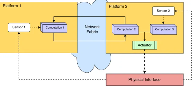
• Physical Layer–CPSsintegrate computation with physical processes. This types of processes are not connected with the digital world and can include elements as mechanical systems or humans. Moreover, physical processes can be composed by many concurrent activities, arising challenges in the modeling stage [Der+12a].
• Sensors and Actuators Layer –CPSs use several sensors to monitor and collect information about the physical environment and use actuators to interact with the physical world, coupling the cyber world with the physical layer.
C H A P T E R 2 . BAC KG R O U N D
behavior, responding to changing conditions and anticipating transformations in the physical processes [Shi+11]. Therefore, the system inherits the capability to reorganize and reconfigure dynamically.
• Network Layer–CPSscan exchange information between systems, communicate through the Internet or connect with other devices and sensors using network fab-rics that provide communication channels, such as wired or wireless networks, Bluetooth,Global System for Mobile Communications (GSMs), etc. [Hu13].
Abstracting the granularity detail inCPS’s concept, the control layer and sensors/ac-tuators layer structure the platform layer. A system may have one or more platform, connected through a network fabric that allows data transfer. Fig.2.1shows a simplified layout of aCPS.
To summarize, thecyberframework includes control, sensors and actuators layers and thephysicalframework includes physical objects and processes. Finally, the network layer links both frameworks.
Figure 2.1: Simplified layout of aCPS
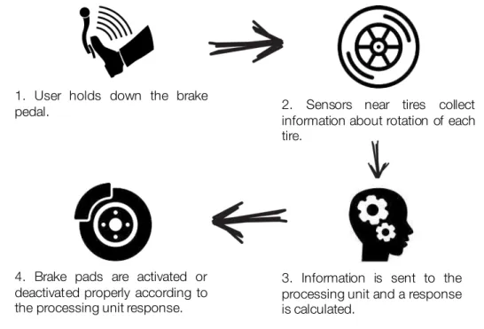
An example of a well-knownCPSis the Anti-Lock Braking System (ABS) that equips many transportation vehicles [Ant14;Mar10].
This system is composed by a set of sensors, actuators, and control units intercon-nected with each other and it is responsible for preventing the wheels from locking up and skid while braking a vehicle.
The system operation initially begins with a user interaction, by placing the foot on the brake pedal in order to trigger the vehicle braking system. Consequently, a set of sensors distributed by each wheel of the vehicle collect the information about the angular speed of rotation, and then sends it back to the ABS control unit.
2 . 1 . C Y B E R- P H YS I CA L S YS T E M S
In this unit, based in the control instructions implemented, the behavior that will be expressed through the brake pads will be determined to be applied to each wheel.
Each actuator will have an independent behavior according to the response of the ABS control unit, thus preventing the wheels from locking up [Bos].
Fig.2.2presents and describes the operation of an Anti-Lock Braking System (ABS).
1. User holds down the brake
pedal. 2. Sensors near tires collect
information about rotation of each tire.
3. Information is sent to the processing unit and a response is calculated.
4. Brake pads are activated or deactivated properly according to the processing unit response.
C H A P T E R 2 . BAC KG R O U N D
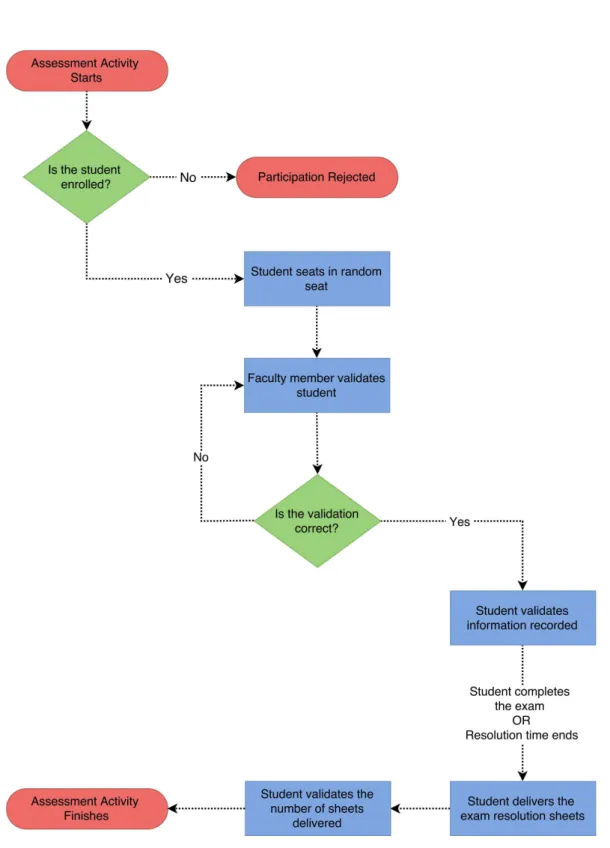
2.2 Typical In-Class Examination Scenarios
Nowadays the control and management of the student’s in-class examination proce-dures is mostly done manually1by the faculty member. This is true at FCT/UNL and generally in the rest of the universities and teaching institutions in Portugal during inter-mediate or final exams.
Through the Faculty’s Information Systems, the student is usually informed about the date, starting times and rooms where the event will take place. Most of the times several rooms have to be used due to the relatively large number of students enrolled, since it may not be possible to fit all the students in a single lecture room.
A typical scenario is that before starting the exam, each student must wait in the doorway of one of the classrooms until he/she is allowed to get inside. Sometimes, atten-dance control must be done to check whether if the student is registered for the specific evaluation activity.
After the entrance, students have to sit in a place of their choice carrying their stu-dent’s card to be verified later.
Then, the faculty member checks each student enrolled in the activity, marking his/her position in the map2with the classroom’s layout. For each student, their student number and their position within the classroom should be recorded. Also, the faculty member may interrupt the student to validate and sign the recorded information, which is a laborious task and can potentially lead to the situation where the student suffers from a loss of concentration and break the line of thought.
At the end of the exam, each student might be asked to register the number of exam res-olution sheets delivered and can be required once again to sign and validate the recorded information (confirming that he/she has finished and handed out the exam). After this, the student can leave the room.
Fig.2.3illustrates the process workflow described of a typical in-class examination activity.
1Without automation.
2For in-place and later fraud control.
2 . 2 . T Y P I CA L I N - C L A S S E X A M I N AT I O N S C E N A R I O S
C
h
a
p
t
e
r
3
Ca s e S t u d y
This chapter contains a detailed description of the proposed case study. It starts with a set of requirements that must be fulfilled followed by an explanation of the architecture and the relationship between several components.
3.1 Requirements of the Proposed Case Study
In order to validate this investigation, it is going to be used an innovative, realistic and comparable case study for education context. The proposed system aims to assist faculty members during evaluation activities in a classroom environment, providing authentication methods, access control, and logistics management.
Owing to the fact that most classrooms are different and some activities require chang-ing the layout of the room, the system must be adaptive since we want to avoid fchang-inger- finger-printing each physical environment. Also, since aGlobal Positioning System (GPS)loose significant power indoors due to the signal attenuation caused by construction materi-als [Kjæ+10], an IPSis going to be used for blueprinting the room and each individual seat. The faculty member responsible for the evaluation activity should mark all valid seats with a mobile phone beforehand.
Furthermore, students have to check-in as they arrive in order to arbitrate a seat position to perform the evaluation activity.
During the activity execution, each student should place their institution ID cards besides themselves with the purpose of being authenticated as their claiming to be and check if they are in the right place.
C H A P T E R 3 . CA S E S T U DY
3.2 Architecture
Regarding the key aspects discussed in section2.1, the proposedCPShas the following architecture:
• Physical Layer– There are two major physical processes that will interact with our system: The marking of valid seats by the faculty member and the authentication/-validation of students enrolled in the evaluation activity. During the marking of places, the system will have to save the coordinate inside the room of each place and after finishing the marking activity, the system will have to create a virtual map of the valid places. Later, for each student who check-in, the system will have to assign a place to hold the activity.
• Sensors and Actuators Layer– Our system is composed by two sensors: Beacons and Temperature Sensors. The first one is responsible for positioning a mobile device inside a classroom and the second reads the environment temperature. In chapter5is described in detail how these sensors work. Also, the system has a built-in display workbuilt-ing as an actuator to display the computed output for a student.
• Control Layer– The control layer is responsible for deciding the behavior of the system based on events of the physical environment. Using logical decisions, the system will have to compute and check different scenarios such as: If the student is enrolled for the activity; If the student is sitting in the assigned place; etc.
• Network Layer– Communication with sensors are performed using two protocols: Bluetooth and 802.11b Wi-Fi. The first one is used between the beacons and mobile device to locate a mobile device inside a classroom. The second one is used to establish communication between the mobile device and the card reader.
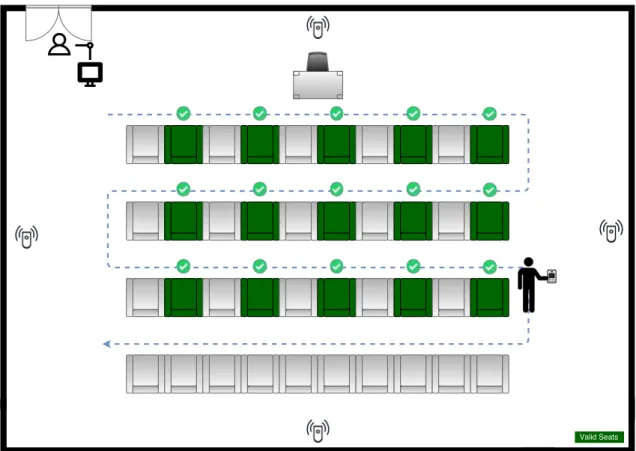
Fig.3.1presents the architecture installation scheme inside a classroom and Fig.3.2 details the entrance control system.
3 . 2 . A R C H I T E C T U R E
Figure 3.1: Scheme of hardware installation in a classroom environment
C
h
a
p
t
e
r
4
A S y s t e m a t i c L i t e r a t u r e R e v i e w
This chapter presents a brief research and study about previous works related to the proposed approach of this thesis. It begins by describing the research process in detail, followed by a presentation of the results. Finally, a brief discussion about the selected results is made followed by a summary of relevant information to retain from this chapter.
ASystematic Literature Review (SLR)is a rigorous process to extensively review all available literature relevant to a particular subject. In order to investigate the work previously developed in the context of this thesis, an approach proposed by Barbara Kitchenham was followed [Kee07].
This process allows through well-defined methodologies to investigate, classify and summarize relevant studies that fulfill various selection criteria.
4.1 Research Method
During the planning of this research and following the guidelines in [Kit+09], four main tasks were identified before starting:
1. Identify and establish theResearch Questions (RQs);
2. Define the search process approach to conduct the research;
3. Formalize the inclusion and exclusion criteria to be applied to the results;
C H A P T E R 4 . A S YS T E M AT I C L I T E R AT U R E R E V I E W
4.1.1 Research Questions
The research questions addressed by this study are described below:
• RQ1– What studies show or suggest the usage ofCPSsin the context of education?
• RQ2– Which languages or model-based tools were studied recently to modelCPSs?
• RQ3– Which techniques were studied recently to implement anIPS?
For eachRQaddressed was applied the PICOC methodology proposed by Petticrew and Roberts [PR08].
4.1.1.1 RQ1 – What studies show or suggest the usage of CPSs in the context of education?
Goal Description: To identify what has been done using CPS in education and what kind of services the system provides.
Search String: "Cyber-Physical System*" [AND] "Education"
PICOC
• Population:Studies regardingCPSs;
• Intervention:Services or activities provided byCPSs;
• Comparison:N/A;
• Outcome:Evidence ofCPSapplications;
• Context:CPSsin education environments.
4.1.1.2 RQ2 – Which languages or model-based tools were studied recently to model CPSs?
Goal Description: To identify and compare evidence in terms of modeling languages, conventions, formalities and tools to support the modeling of CPSs in a top-down ap-proach.
Search String: "Model*" [AND] "Cyber-Physical System*" [AND] "Model-Based"
[AND] "Language*"
4 . 1 . R E S E A R C H M E T H O D
PICOC
• Population:CPSs;
• Intervention:Approaches and frameworks used to modelCPSs;
• Comparison:Different approaches and frameworks used to modelCPSs;
• Outcome:Examples ofCPSsmodeled with different approaches;
• Context:Model-based approaches.
4.1.1.3 RQ3 – Which techniques were studied recently to implement an IPS?
Goal Description: To identify and compare evidence in terms of techniques and tech-nologies used inIPSsto locate targets inside buildings.
Search String: "Technique*" [AND] "Indoor Positioning" [AND] "location" [AND]
"Fingerprint*"
PICOC
• Population:IPSs;
• Intervention:Techniques and technologies used recently;
• Comparison:N/A;
• Outcome:Decide the most appropriate technology to use in the case study;
• Context:N/A.
4.1.2 Search Process
In order to perform theSLR, several well-known digital libraries were selected within the scientific community to provide content.
Table 4.1: Sources of evidence
Source Acronym
ACM Digital Library ACM
IEEE Xplore Digital Library IEEEX
ResearchGate RG
ScienceDirect SD
C H A P T E R 4 . A S YS T E M AT I C L I T E R AT U R E R E V I E W
4.1.3 Selection Criteria
In order to refine and filter the set of results obtained in eachRQ, a selection criteria to include and exclude studies was defined. Through this selection, the potential selected studies will have a higher probability to answer the correspondingRQs. As a result, the inclusion criteria outlined is the following:
• Studies where at least one of the keywords that form the search string appears in the publication title;
• Studies where at least one of the keywords that form the search string appears in the publication abstract;
• Studies which abstract is related to the same context of this work;
• Source of knowledge is written in English.
On the contrary, the exclusion criteria is the opposite of inclusion criteria.
4.1.4 Quality Assessment
The aim of this section is to assess the quality of the research performed and the selected studies during this process. Following theQuality Assessment (QA)questions outlined by Kitchenham et al. [Kit+09], the followingQAswere obtained:
• QA1– Are the review’s inclusion and exclusion criteria described and appropriate?
• QA2– Is the literature search likely to have covered all relevant studies?
• QA3– Did the reviewers assess the quality/validity of the included studies?
• QA4– Were the basic data/studies adequately described?
With regard toQA1, the inclusion criteria was detailed in section4.1.3and is appro-priate to the study conducted. Also, the exclusion criteria was mentioned, considering the opposite of inclusion criteria. Therefore, any study that not met all the inclusion criteria conditions was discarded.
Moreover, forQA2, the research was conducted in five digital repositories well-known within the scientific community, as mentioned in section4.1.2. Considering these factors, it can be concluded that the research obtained all relevant studies.
Also, forQA3, the quality/validity of data was also considered, ensuring that authors were experts from the addressed study area and that the data presented were corroborated by other authors.
Finally, forQA4, in sections4.2.1,4.2.2and4.2.3was performed a brief summary of each selected study. Ahead, in chapter5are presented the results in further detail.
4 . 1 . R E S E A R C H M E T H O D
4.1.5 Data Collection
The data extracted from each result were the following:
• Title;
• Author(s);
• Keywords;
• Year;
• Location (URL);
• Source of Evidence;
• Date of Publication;
• Personal Impressions.
4.1.6 Data Analysis
The extracted data from studies was tabulated to present:
• No. Studies Found– Represents the number of studies1found in each digital repos-itory for eachRQ;
• No. Potential Studies – Represents the number of filtered studies after applying the inclusion and exclusion criteria for eachRQ;
• No. Selected Studies– Represents the number of selected studies relevant to this thesis after reading the full text article.
C H A P T E R 4 . A S YS T E M AT I C L I T E R AT U R E R E V I E W
4.2 Results
The aim of this section is to analyze the results of theSLR. In each statistics table, each column representation is defined in section4.1.6. Also, duplicated results were ignored when considering the number of studies found.
4.2.1 Results for RQ1
Table 4.2: Statistics of search results for RQ1
Digital Library No. Studies Found No. Potential Studies No. Selected Studies
ACM 15 0 0
IEEE Xplore 16 3 1
ResearchGate 10 0 0
ScienceDirect 3 0 0
Springer Link 14 0 0
Total 58 3 1
Table 4.3: Summary of selected results for RQ1
Reference Summary
[Lei+13] This paper proposes aCPSto analyze and control the thermal environ-ment of an academic laboratory in order to optimize the performance of the experiments conducted.
4 . 2 . R E S U LT S
4.2.2 Results for RQ2
Table 4.4: Statistics of search results for RQ2
Digital Library No. Studies Found No. Potential Studies No. Selected Studies
ACM 30 4 1
IEEE Xplore 56 13 5
ResearchGate 14 2 1
ScienceDirect 11 2 0
Springer Link 17 0 0
Total 128 21 7
Table 4.5: Summary of selected results for RQ2
Reference Summary
[Der+12b] This paper discusses the various challenges ofCPSmodeling, proposes solutions to address this problems, identifies various tools and tech-nologies used to modelCPSs and exemplifies the modeling of a fuel tank of an airplane.
[Fri11] This paper addresses the Modelica and ModelicaML modeling lan-guages and introduces the OpenModelica environment. Also, it presents a description of Modelica tool and several advantages over the Simulink tool. Finally, enumerates a set of modeling tools depending on each type ofCPSmodeling.
[Tan+12] This paper describes the Modelica tool and discusses why Modelica is capable to model and simulateCPSs.
[Jen+11] This paper proposes a design methodology ofCPSs and for each dif-ferent design stage, a description of the process is made. To conclude, it is proposed aCPSusing the approach proposed by the authors, de-scribing each step in the context of the problem.
[Lat+12] This paper presents a framework called CyPhyML and explores its characteristics to modelCPS.
[Nak+12] This paper shows a comparison between modeling tools SysML and Simulink in relation to the modeling and design ofCPS.
C H A P T E R 4 . A S YS T E M AT I C L I T E R AT U R E R E V I E W
4.2.3 Results for RQ3
Table 4.6: Statistics of search results for RQ3
Digital Library No. Studies Found No. Potential Studies No. Selected Studies
ACM 0 0 0
IEEE Xplore 63 9 6
ResearchGate 0 0 0
ScienceDirect 4 0 0
Springer Link 44 4 0
Total 111 13 6
Table 4.7: Summary of selected results for RQ3
Reference Summary
[AA+14] This paper compares state-of-the-art algorithms, techniques and tech-nologies used inIPSsand present the advantages and disadvantages of each technique and technology. Also, the authors focus performance metrics ofIPSs.
[Dar+15] This paper presents a comparison of existingIPSs, detailing the mea-surement technique, accuracy, advantages and disadvantages of each technology.
[Kim+15] This paper describes currentIPStechniques and analyzes various se-curity threats and vulnerabilities ofIPS.
[FH15] This paper proposes anIPSusingBLEbeacons. Further, the authors presents advantages and drawbacks of this technology and perform an experimentation aiming to check the performance of the system with different configuration parameters.
[Ji+15] This paper presents a comparison of an indoor location system using two different technologies: Wi-Fi access point signals orBLEsignals. Besides the theoretical analysis, it presents an experience which com-pares the degradation of strength due to the distance from the signal transmitter and the accuracy error of the different technologies. [Liu+07] This paper introduces existingIPSsand techniques used to calculate
the target position. Also it presents a set of properties that characterize these systems. However, since this paper was published in 2007, it will only be used as a reference owing to the fact that technology is out-of-date.
4 . 3 . D I S C U S S I O N
4.3 Discussion
Based on the small result set number of papers related withRQ1, it can be argued that the low number of results would be expected to collect. According to the ideas pre-sented in section3.1, it is proposed to develop a groundbreaking case study using aCPS approach and nowadays,CPSsare seldom used in the context of education. During the snowball process, there were some potential papers that address the lack of engineers in the area ofCPS or the need to specialize and certify students in emerging technolo-gies. In some cases, simplified and small systems have been developed to test and apply knowledge acquired in classes.
Moreover, the result set fromRQ2 explored several modeling languages and tools with different capabilities. Also, some researchers have proposed prototype tools but for pragmatic reasons related to the purpose of the work, we will only consider commercial tools that follow the standard proposed by theObject Management Group (OMG). Since the proposed system is discrete, the language/framework chosen must have the capability to model and simulate the system, which will be a criteria to be taken into account to make the choice. Most importantly, the language must be able to model the system without being dependent on the hardware or technology chosen.
Additionally, based on the results ofRQ3, it can be argued that it is a fairly inves-tigated area with various techniques and technologies proposed in the past. However, knowing the technology evolves quickly, there was a special attention to studies published before 2010 since the presented technology may be out of date.
4.4 Summary
After examining the available literature identified in tables4.3,4.5, and4.7, we are able to state thatCPSswere seldom used in the education context. Moreover, considering the outcome of RQ1, it can be concluded that there is no solution similar to what we intend to develop, justifying that one of the outcomes of this work is a groundbreaking case study.
Furthermore, inRQ2, there was obtained a large set of modeling languages, were some of them were prototypes proposed by several investigators. From this result set, we will only consider commercial tools that follow the proposed standards.
C
h
a
p
t
e
r
5
R e l a t e d Wo r k
This chapter contains a detailed analysis of the results selected in the previous chapter. For each research question, a comparison is made between the various available solutions, ending each section with a detailed analysis of the chosen solu-tion.
5.1 Modeling Cyber-Physical Systems
As previously mentioned,CPSmodeling is a sophisticated task due to the scale and heterogeneity of the system [Der+12b;Lee+08]. Many researchers propose tools such as
SICYPHOS[Waw+15],Ptolemy[Der+12b] orCyPhyML[Lat+12]. However, we intend to analyze only stable frameworks widely accepted by the research community.
Analyzing the set of results obtained in RQ2 and verifying which are the most com-monly used tools/frameworks to modelCPSs, resulted in the following selection:
• LabVIEW;
• Modelica;
• ModelicaML;
• Simulink;
C H A P T E R 5 . R E L AT E D WO R K
5.1.1 Comparison of Frameworks/Tools
According to Fritzson, some tools are specialized in a single application domain while others are more general. For that reason, the author suggests that Simulink and conse-quently LabVIEW are used by convention to model continuous systems. Although it is proposed in the case study a discrete system, it is intended to use a scalable modeling solution, allowing the evolution of a discrete system to a hybrid system [Fri11].
Moreover, SysML is a hybrid graphical modeling language capable of creating high-level system models that may cover different domain aspects and capture complex system descriptions such as structure, behavior, properties and requirements [Par+10]. Based on theUnified Modeling Language (UML)notation, SysML can model both continuous and discrete systems using a reuse design approach by decomposing the whole system into var-ious subsystems [Nak+12]. However, SysML only has the potential to describe the system behavior but cannot simulate its execution unlike Modelica or ModelicaML [Pop+07].
On the other hand, Modelica is a hybrid object-oriented mathematical modeling lan-guage with powerful simulation capabilities [Lat+12]. This language allows to describe models using a declarative, modular and hierarchical approach that combines different formalities. Among the several advantages over existing modeling tools, Pop et al. stated that Modelica features the ability to naturally correspond the structure of the model to the physical structure of the system unlike block-oriented modeling tools such as Simulink [Fri11;Pop+07].
The descriptive and graphical capabilities of SysML and the expressiveness and simu-lation power associated with Modelica led to the creation of a single complete language: ModelicaML. This tool benefits of the graphics capabilities offered byUML/SysML with the expressiveness and simulation capabilities of Modelica, allowing verification and validation of system requirements [Sch+09].
5.1.2 ModelicaML
With regard to what was argued in section5.1.1, evidence suggests that ModelicaML has all capabilities needed to model the system proposed in the case study.
ModelicaML is a UML profile for Modelica, based on a subset of UML and SysML concepts that allows in an effective way to create and interpret Modelica models. More-over, since ModelicaML extends a subset of UML, reuses SysML artifacts, and provides new types of diagrams that were missing in Modelica concepts, allows to offer powerful executable diagrams with precise semantics based on Modelica language [Sch+09].
When the modeler wants to execute and simulate the modeled system, ModelicaML models are converted to Modelica code and compiled in Modelica tool. The concept of execution is described in Fig.5.1.
5 . 1 . M O D E L I N G C Y B E R- P H YS I CA L S YS T E M S
Figure 5.1: ModelicaML execution concept [Sch13]
C H A P T E R 5 . R E L AT E D WO R K
Fig.5.2shows the most relevant profile diagrams available in ModelicaML. As shown in the figure, Requirement, Activity, Sequence, State Machine, Use Case and Parametic diagrams are reused from SysML and have the following utility [Omg]:
• Requirement Diagram– Allows the composition of system requirements;
• Activity Diagram– Allows to demonstrate the behavior of the system using data or control flows. The activities can be composed or decomposed;
• Sequence Diagram– Allows to model the interaction between system parts based on a time sequence;
• State Machine Diagram– Allows to describe the state actions/transactions that a system/subsystem perform in response to events;
• Use Case Diagram– Allows the capture of interaction between external actors with the system or subsystems;
• Parametric Diagram– Allows to represent constraints on system property values such as performance or reliability.
Also, Internal Class, Class and Package diagram were reused from SysML diagram taxonomy with slight changes [Pop+07]:
• Class Diagram– Renamed from SysML/Block Definition Diagram – Responsible for class definitions and relationships between classes;
• Internal Class Diagram – Renamed from SysML/Internal Block Diagram – De-scribes internal class structure and interconnections between parts;
• Package Diagram– Responsible for supporting specifics of Modelica packages.
To conclude, Simulation and Equation diagrams were added to ModelicaML profile:
• Simulation Diagram – Allows to configure parameter settings and variables in order to simulate the execution of the system;
• Equation Diagram– Specifies the behavior of each component using equations.
An example using the graphical notation of ModelicaML is presented in Fig.5.3.
5 . 2 . I N D O O R P O S I T I O N I N G S YS T E M S
Figure 5.3: ModelicaML graphical notation – Two tanks system example [Sch13]
5.2 Indoor Positioning Systems
As mentioned before,GPSslose significant power indoors due to the signal attenu-ation caused by construction materials [Kjæ+10]. For this reason, an IPSis needed to locate targets inside buildings.
Analyzing the set of results obtained in RQ3, it was found that it is a fairly investigated area with a large amount of available technological solutions that offer different features.
5.2.1 Comparison of Techniques and Technologies
Al-Ammar et al. identified several metrics to describe anIPS[AA+14]:
• Accuracy– Defines the quality between the measured distance and the actual dis-tance;
• Availability– Defines the percentage of time that the system is available to be used ensuring the accuracy described;
• Cost– Defines the cost of the hardware, system maintenance and energy consumed to keep the system running;
• Coverage Area– Defines the maximum area coverage that the system can cover to locate targets successfully;
• Privacy– Defines the data privacy policies collected by sensors and access control permissions over the system;
C H A P T E R 5 . R E L AT E D WO R K
Following the metrics presented above, the proposed system must have a good accu-racy, cover at least the entire environment in a classroom, have high scalability and have a low cost of execution and implementation. In order to review the most used existing technological solutions, Tab. 5.1 is presented to compare each technology aspect, with data taken from [AA+14] and [Dar+15].
Table 5.1: Comparison of existing indoor position technologies [AA+14;Dar+15]
Technology Accuracy Advantages Disadvantages
Bluetooth Low Energy (BLE)
Connectivity Range
High compatibility with a wide range of devices; Good indoor coverage with low power consumption; Cheap hardware.
Larger areas increase the cost of installation since it is necessary to buy more re-ceivers to maintain accuracy; Vulnerable to signal interfer-ence since it operates in an unlicensed band.
Cellular Based
20m - 500m1 No interference with other devices.
Low accuracy due to signal attenuations.
RFID Connectivity
Range
Good indoor coverage with low power consumption; Good propagation of signal through obstacles.
Hard integration with other systems; Unsecured commu-nication.
Ultra-Wideband (UWB)
0.1m - 1m High accuracy; Good propa-gation of signal through ob-stacles; No interference with other devices.
High cost of hardware; Some materials may interfere with the signal.
Wi-Fi 1m - 5m Cheap hardware; Line of sight between transmitter and receiver is not required; High compatibility with a wide range of devices;
Require Wi-Fi fingerprint-ing; Physical activities in the environment may change the signal strength.
ZigBee 1m - 10m Cheap hardware with low power consumption;
Relatively low accuracy; Vul-nerable to signal interfer-ence since it operates in an unlicensed band.
Given that accuracy is a crucial factor in the proposed system and regarding the accuracy metric in Tab.5.1, the Cellular and ZigBee technologies will be discarded from the technological choice available. Also, since UWB technology is expensive and RFID has a hard integration with other systems, both technologies will also be discarded.
In order to choose the technological solution between Bluetooth and Wi-Fi to imple-ment theIPS, both technologies will have to be analyzed in further detail.
According to Kim et al., Bluetooth 4.0 specifications were adopted into Bluetooth standards in 2010 and BLE was released later [Kim+15]. BLE is a wireless standard aimed toInternet of Things (IoT)solutions that provide a similar communication range
1Differs depending on the network available: 2G, 3G or LTE.
5 . 2 . I N D O O R P O S I T I O N I N G S YS T E M S
as Bluetooth classic but with reduced power consumption, since it is not connection oriented [Ble].
Ji et al. conducted a detailed analysis using Wi-Fi based stations and BLE bea-cons [Ji+15]. A beacon is a small device that usesBLE technology and broadcasts an advertising package described in Fig.5.4.
Figure 5.4: iBeacon data format [App14]
When the mobile device receives the advertising package, the distance between the mobile device and the beacon station can be measured using the beacon ID and the signal strength. Although the distance can be computed using a single beacon device, accuracy can be improved by adding more beacons into the physical plant [Kim+15].
BLEoperates using a 2.4GHz unlicensed band as well as Wi-Fi but with lower Trans-mission Power (Tx)and short duration messages to improve battery life. For that reason, more beacons are needed to archive similar accuracy when compared to Wi-Fi technology. Also, battery life depends on configuration parameters such as transmission power or advertise rate [FH15].
In order to compare both technologies, Ji et al. setup a test environment and used two different mobile devices to receive the advertise packages and compare the signal strength of both technologies over different distances.
(a) Received Signal Strength on Nexus 5 (b) Received Signal Strength on Samsung Note 3
C H A P T E R 5 . R E L AT E D WO R K
Based in Fig.5.5, evidence suggests that distinct mobile devices may obtain different measurements. Also, the authors simulated different strategies of transmitters distribu-tion: Random Topology and Grid Topology. The full analysis is published in [Ji+15].
Furthermore, Faragher and Harle identified several challenges related to the use of Wi-Fi technology [FH15]:
• Long duration of Wi-Fi scans– Wi-Fi tethering is relatively slower when compared to BLE scan. Hence, the update of the target position is slower using Wi-Fi;
• Increased network traffic– Broadcast packets used for communication between
transmitters and mobile devices increase network traffic and reduce data transmis-sion rates;
• Limited access to Wi-Fi services – Some platforms do not allow access to Wi-Fi services directly, preventing third-party applications to perform Wi-Fi tethering or fingerprinting;
• Higher energy consumption at the mobile device– Wi-Fi tethering requires more energy at the mobile device thanBLEscan sinceBLEprotocol was developed and optimized considering continuous scan operation.
Also, the authors concluded thatBLEtechnology is more accurate, since the results showed “accuracies of <2.6m 95% of the time using a dense beacon distribution (1 beacon per 30 m²) and <4.8m using a lower density distribution (1 beacon per 100 m²) in an environment where Wi-Fi achieved only <8.5m 95% of the time”.
5.2.2 BLE Beacons
With regard to what was argued in section5.2.1, evidence suggests thatBLE technol-ogy has all capabilities to implement theIPSrequired in the case study proposed.
Given the available commercial solutions, it will be used beacons produced by a has named "Estimote". Their product runs on a coin-typed lithium battery and has an autonomy up to 5 years using low energy settings. Also, Estimote Beacons are build using an ARM M0 Cortex processor,BLEantenna, motion and temperature sensors, providing a range of operation up to 70 meters [Esta]. Moreover, Estimote provides an Indoor SDK that allows the developer to map the physical plant using a custom app and see real-time user positions within that space, with an accuracy of 1 to 4 meters depending on location size [Bor15]. However, Indoor SDK requires at least 4 beacons to operate and it is only available for IOS platform, forcing the initial development of the client app to this platform. Also, Indoor SDK works withObjective-C[Obj] orSwift[Swi], leaving the technology choice to the user’s criteria. Fig.5.6shows the hardware assembly of a single beacon.
5 . 3 . D E V E LO PM E N T P R O C E S S
Figure 5.6: Hardware assembly of Estimote beacons [Esta]
5.3 Development Process
In order to develop the proposed system, Jensen et al. have identified a number of steps aimed to support the modeling and development ofCPSs. The proposed method-ology addresses the development process from its specification to its realization and is divided into several codependent steps [Jen+11]:
1. State the Problem– The first step is to define the problem to be solved with clear textual language so that anyone can understand what is intended to do;
2. Model Physical Process– The second step is to start sketching the physical model by analyzing the environment and the physical processes that are going to interact with theCPS;
3. Characterize the Problem – The third step is to identify parameters of physical processes to be controlled. For instance, parameters such as room capacity or fault conditions;
4. Derive a Control Algorithm– The fourth step is to establish a control algorithm to be implemented and executed in the control layer of theCPS;
5. Selects Models of Computation– The fifth step is to definemodels of computation
that contain the set of allowable operations used in computation and the rules of interaction between entities;
C H A P T E R 5 . R E L AT E D WO R K
7. Simulate– The seventh step is to simulate theCPSin a virtual environment before assembling the hardware. This step avoid mistakes that can be costly at a further stage.
8. Construct– The eighth step is to build the system according to specifications. Each subsystem must be build and tested until the fullCPSis completed.
9. Validation and Testing– The ninth step is to test theCPSand validate if the speci-fied requirements are fulfilled. All control conditions must be tested and the system behavior must be equal to the result obtained inStep 7.
After reviewing the methodology proposed by the author, we find it suitable to model the proposed system. Therefore, the method presented above will be followed during the development of theCPSproposed in the case study.
C
h
a
p
t
e
r
6
C o n c e p t u a l i z a t i o n a n d I m p l e m e n t a t i o n
This chapter presents a detailed description of the prototype developed in this dissertation. It begins by introducing the modeling of the system through the requirements engineering processes, followed by the implementation details of the remaining subsystems that complement the proposed solution.
6.1 Requirements Engineering
In order to model and implement the proposed solution, a traditional process of engineering will be followed. Requirements Engineering is a process that aims to find, document, analyze and verify the purposes of a system with the purpose of ensuring that the customer needs are satisfied and the product functionalities are respected, without compromising the requirements of the system to be developed [Som09].
To ensure the solution developed meets a set of functionalities and constraints implicit in the educational system in the most teaching establishments, a feasibility study and the elicitation and analysis of requirements were carried out with the help of domain experts.
After this process was completed, the system modeling process was started.
6.1.1 Use Case Diagram
C H A P T E R 6 . CO N C E P T UA L I Z AT I O N A N D I M P L E M E N TAT I O N
Figure 6.1: E-Presence System - ModelicaML use case diagram
6 . 1 . R E Q U I R E M E N T S E N G I N E E R I N G
6.1.2 Use Case Descriptions
The use cases specified in subsection6.1.1are further detailed and accomplished with use case descriptions. The template used is based on the use case template presented by Larman [Lar04].
Use Case 1 Login
Description: This use case describes how the Faculty Member au-thenticates into the E-Presence app.
Primary Actor: Faculty Member.
Preconditions: • System must be running;
• E-Presence DB must be reachable;
• Academic Authentication System must be reachable;
• User is not authenticated.
Postconditions: User is successfully authenticated.
Main Success Scenario:
1. The use case begins when the Faculty Member starts the app;
2. The Faculty Member inputs the authentication credentials and submits;
3. The system queries the E-Presence database to verify if the credentials submitted are correct;
4. The system displays the home display;
C H A P T E R 6 . CO N C E P T UA L I Z AT I O N A N D I M P L E M E N TAT I O N
Alternatives:
2.a The Faculty Member selects the Academic Sign-In authentication button:
1. The system requests the user credentials in the academic authenti-cation system;
2. The academic authentication system replies the request;
3. The use case resumes at Step 3 of the main scenario.
3.a The system cannot find the user or the password is incorrect:
1. The system displays a feedback message;
2. The use case ends.
6 . 1 . R E Q U I R E M E N T S E N G I N E E R I N G
Use Case 2 Select Course
Description: This use case describes how the Faculty Member se-lects a course using the E-Presence app.
Primary Actor: Faculty Member.
Preconditions: • System must be running;
• E-Presence DB must be reachable;
• User is authenticated.
Postconditions: Course is selected successfully.
Main Success Scenario:
1. The use case begins when the Faculty Member selects the current course;
2. The courses controller queries the E-Presence database to check all courses for which the user authenticated is responsible;
3. The system prompts the list of courses fetched;
4. The Faculty Member selects the desired course;
C H A P T E R 6 . CO N C E P T UA L I Z AT I O N A N D I M P L E M E N TAT I O N
Use Case 3 View Students List
Description: This use case describes how the Faculty Member uses the E-Presence app to view the list of students en-rolled in a course.
Primary Actor: Faculty Member.
Preconditions: • System must be running;
• E-Presence DB must be reachable;
• User is authenticated.
Postconditions: The list of students is displayed successfully.
Main Success Scenario:
1. The use case begins when the Faculty Member selects Students;
2. The students controller queries the E-Presence database to check all stu-dents enrolled in the selected course;
3. The system displays the list of students;
4. The use case ends successfully.
6 . 1 . R E Q U I R E M E N T S E N G I N E E R I N G
Use Case 4 View Student Details
Description: This use case describes how the Faculty Member uses the E-Presence app to view the details of a student.
Primary Actor: Faculty Member.
Preconditions: • System must be running;
• E-Presence DB must be reachable;
• User is authenticated;
• The student record is created.
Postconditions: Student details are displayed successfully.
Main Success Scenario:
1. The use case begins when the Faculty Member selects the student;
2. The students controller queries the E-Presence database to find the se-lected student;
3. The system displays the details of the student;
C H A P T E R 6 . CO N C E P T UA L I Z AT I O N A N D I M P L E M E N TAT I O N
Use Case 5 View Activity Schedule
Description: This use case describes how the Faculty Member uses the E-Presence app to view the evaluation activity schedule.
Primary Actor: Faculty Member.
Preconditions: • System must be running;
• E-Presence DB must be reachable;
• User is authenticated.
Postconditions: Scheduled activities are displayed successfully.
Main Success Scenario:
1. The use case begins when the Faculty Member selects the Classes or Evaluations mode;
2. Ifthe user is in class mode;
1. The turns controller queries the E-Presence database to find all class turns from the selected course and displays the results;
2. The Faculty Member selects a specific turn;
3. The classes controller queries the E-Presence database to find all class activities scheduled for the selected turn and course;
3. Else
1. The evaluations controller queries the E-Presence database to find all evaluation activities of the selected course;
end if;
4. The system displays the results;
5. The use case ends successfully.
6 . 1 . R E Q U I R E M E N T S E N G I N E E R I N G
Use Case 6 Create New Activity
Description: This use case describes how the Faculty Member uses the E-Presence app to create a new activity.
Primary Actor: Faculty Member.
Preconditions: • System must be running;
• E-Presence DB must be reachable;
• User is authenticated.
Postconditions: New activity is created successfully.
Main Success Scenario:
1. The use case begins when the Faculty Member selects Create New Activ-ity;
2. Ifthe user is in class mode;
1. The classes controller queries the E-Presence database to check all available rooms;
3. Else
1. The evaluations controller queries the E-Presence database to check all available rooms;
end if;
4. The system displays the form that prompts the activity description name, room, start time, end time and the time allowed to enter before the activ-ity starts and the time allowed to leave before the activactiv-ity ends;
5. The Faculty Member submits the requested information;
6. The system displays a feedback message;
C H A P T E R 6 . CO N C E P T UA L I Z AT I O N A N D I M P L E M E N TAT I O N
Use Case 7 Edit Activity Details
Description: This use case describes how the Faculty Member uses the E-Presence app to edit an activity.
Primary Actor: Faculty Member.
Preconditions: • System must be running;
• E-Presence DB must be reachable;
• User is authenticated;
• The activity to be edited is created.
Postconditions: Activity details are edited successfully.
Main Success Scenario:
1. The use case begins when the Faculty Member selects Edit Activity;
2. Ifthe user is in class mode;
1. The classes controller queries the E-Presence database to check all available rooms;
3. Else
1. The evaluations controller queries the E-Presence database to check all available rooms;
end if;
4. The system displays the edit form filled with the current information;
5. The Faculty Member submits the requested information edited;
6. The system displays a feedback message;
7. The use case ends successfully.
![Figure 5.2: ModelicaML diagram overview [Pop+07]](https://thumb-eu.123doks.com/thumbv2/123dok_br/16521334.735665/49.892.137.759.781.1053/figure-modelicaml-diagram-overview-pop.webp)
![Figure 5.3: ModelicaML graphical notation – Two tanks system example [Sch13]](https://thumb-eu.123doks.com/thumbv2/123dok_br/16521334.735665/51.892.204.689.150.405/figure-modelicaml-graphical-notation-tanks-example-sch.webp)
![Table 5.1: Comparison of existing indoor position technologies [AA+14; Dar+15]](https://thumb-eu.123doks.com/thumbv2/123dok_br/16521334.735665/52.892.132.759.319.882/table-comparison-existing-indoor-position-technologies-aa-dar.webp)
![Figure 5.5: Experimental results of received signal strength for Wi-Fi and BLE [Ji+15]](https://thumb-eu.123doks.com/thumbv2/123dok_br/16521334.735665/53.892.138.762.835.1046/figure-experimental-results-received-signal-strength-wi-ble.webp)


