João Carlos Tanganho de Sousa
Mestrado em Engenharia InformáticaParallel Run-Time for CO-OPN
Dissertação para obtenção do Grau de Mestre em Engenharia Informática
Orientadores :
João Manuel Santos Lourenço, Prof. Auxiliar,
Universidade Nova de Lisboa
Vasco Amaral, Prof. Auxiliar,
Universidade Nova de Lisboa
Júri:
Presidente: Manuel Próspero dos Santos
Arguente: Salvador Luís Bethencourt Pinto Abreu
iii
Parallel Run-Time for CO-OPN
Copyright cJoão Carlos Tanganho de Sousa, Faculdade de Ciências e Tecnologia, Uni-versidade Nova de Lisboa
Acknowledgements
Abstract
Domain Specific Modeling (DSM) is a methodology to provide programs or system’s specification at higher level of abstraction, making use of domain concepts instead of low level programming details. To support this approach, we need to have enough expressive power in terms of those domain concepts, which means that we need to develop new languages , usually termed Domain Specific Languages (DSLs).
An approach to execute specifications developed using DSLs goes by applying a model transformation technique to produce a specification in another language. These transformation techniques are applied sucessively until the specification reaches a lan-guage with an implemented run-time. The lanlan-guage named Concurrent Object-Oriented Petri Nets (CO-OPN) is being used successfully as a target language for such model trans-formation techniques.
CO-OPN is an object-oriented formal language for specifying concurrent systems, that separates coordination from computational tasks. CO-OPN offers mechanisms to define the system structure and behavior, and like DSLs, relieves the developer from stipulate how that structure and behavior are attained by the underlying system.
x
By guaranteeing a safe execution environment, CO-OPN becomes an alternative to the way parallel software is nowadays developed.
Resumo
A Modelação Específica do Domínio (MED) é uma metodologia que abstrai o pro-cesso de desenvolvimento dos detalhes da implementação, utilizando os conceitos do domínio em vez de terminologia ligada à implementação. Para suportar este conceito, é necessário existir expressividade suficiente em termos dos conceitos do domínio, o que implica que é necessário desenvolver e criar novas linguagens de programação, geral-mente referidas como Linguagens de Domínio Específico (LDE).
Uma abordagem para executar as especificações desenvolvidas através das LDE passa pela aplicação de uma técnica de transformação de modelos que produz uma especifi-cação numa outra linguagem. As técnicas de transformação de modelos são aplicadas recursivamente até ser atingida uma especificação definida numa linguagem com um ambiente de execução devidamente implementado. A linguagem conhecida como Con-current Object-Oriented Petri Nets (CO-OPN), está a ser actualmente utilizada como lin-guagem alvo destas técnicas de transformação de modelos.
A CO-OPN é uma linguagem formal orientada para objectos e que modela sistemas concorrentes. A linguagem separa as tarefas de coordenação das tarefas de computação e oferece mecanismos para definir a estrutura do sistema e o seu comportamento. Con-tudo, tal como as LDE, afasta o programador dos detalhes relativos à implementação da estrutura e ao comportamento do sistema.
O actual gerador de código para a CO-OPN apenas produz código sequencial, apesar das especificações poderem expressar comportamentos concorrentes. O código gerado pode ser executado num ambiente de execução sequencial ou num simulador passo-a-passo, oferecido pelo ambiente de desenvolvimento designado porCO-OPN Builder. A geração de código apenas sequencial é uma desvantagem para o CO-OPN pois as especi-ficações concorrentes não podem ser executadas em paralelo, pelo que o potencial desta linguagem não é totalmente aproveitado.
xii
gerador de código existente e alteração dos mecanismos de suporte à execução actuais. Desta forma, todas as especificaões concorrentes que fazem da CO-OPN a linguagem alvo, beneficiariam de um código seguro para uma execução concorrente, libertando o programador dos detalhes da programação paralela.
Ao garantir um ambiente de execução seguro, a CO-OPN torna-se uma alternativa à forma como o desenvolvimento de software paralelo é feito hoje em dia.
Contents
1 Introduction 1
1.1 Overview and Motivation . . . 1
1.2 Problem Statement and Goals . . . 2
1.3 Contributions of this Dissertation . . . 4
1.4 Document Outline . . . 4
2 Concurrent Object-Oriented Petri Nets (CO-OPN) 7 2.1 CO-OPN Underlying Formalisms . . . 7
2.1.1 Petri-Nets . . . 7
2.1.2 Algebraic Specifications — Order Sorted Algebra . . . 8
2.1.3 Idealized Workers Idealized Managers Model (IWIMM) . . . 8
2.2 CO-OPN Components . . . 9
2.2.1 Abstract Data Types (ADTs) . . . 9
2.2.2 Classes . . . 9
2.2.3 Contexts . . . 12
2.3 From CO-OPN to Java . . . 14
2.4 Simulator and Sequential Run-Time . . . 15
2.4.1 Logical Instants . . . 15
2.4.2 Representing Synchronization Policies . . . 16
2.4.3 CO-OPN Non-Determinism and Backtracking . . . 18
3 Related Work 21 3.1 Domain Specific Modelling (DSM) . . . 21
3.1.1 DSM Goals . . . 21
3.1.2 Domain Specific Languages (DSLs) . . . 22
3.2 Communication in Concurrent Systems . . . 23
3.2.1 Message Passing . . . 23
3.2.2 Remote Procedure Call (RPC) . . . 24
3.3 Concurrency Control for Management of Shared Data Contention . . . 27
3.3.1 Execution Models and Support . . . 27
3.3.2 Specification Models . . . 30
CONTENTS
4 A Parallel Run-Time for CO-OPN 33
4.1 Requirements for Parallel Execution of CO-OPN Specifications . . . 33
4.1.1 Synchronization Operators Semantic . . . 33
4.1.2 Logical Execution Semantics . . . 34
4.1.3 Protecting the Marking from Concurrent Accesses . . . 35
4.2 Representing Logical Instants . . . 35
4.3 Enforcing Logical Execution . . . 37
4.3.1 Depth-First Execution . . . 38
4.3.2 Breadth-First Execution . . . 39
4.4 CO-OPN Places . . . 44
4.5 Handling Simultaneous Pre/Test Conditions . . . 45
4.6 Supporting Backtracking . . . 46
4.7 Handling Distribution . . . 47
5 The Parallel Code Generator 49 5.1 Modular Code Generation Approach . . . 49
5.2 Parallel Run-Time . . . 51
5.2.1 Support for Logical Instants . . . 51
5.2.2 Support for Concurrency Aware Places . . . 53
5.2.3 Time Stamp Manager . . . 57
5.3 Implementation of Methods and Gates . . . 59
5.3.1 Handling Pre/Test Conditions . . . 60
5.3.2 Handling Synchronizations . . . 60
5.3.3 Handling Post Conditions . . . 64
5.3.4 Handling Method Backtracking . . . 64
5.4 Distributing CO-OPN Entities . . . 65
6 Use Case: The Producer—Consumer Problem 69 6.1 Introduction . . . 69
6.1.1 One Producer and One Consumer . . . 69
6.1.2 Multiple Producers and Consumers . . . 75
6.2 Performance and Comparison Tests . . . 75
6.2.1 Test Results . . . 76
6.2.2 Results Discussion . . . 79
List of Figures
1.1 CO-OPN used as a target language for DSLs . . . 3
1.2 Expected Contributions of this dissertation . . . 5
2.1 An example of a Petri-Net . . . 8
2.2 Outline of theBasicTnode . . . 10
2.3 A CO-OPN Context . . . 13
2.4 Specification of ContextPingPong . . . 14
2.5 Instant Representation Tree . . . 16
2.6 Instant Subdivision Tree and Nested Transactions . . . 17
2.7 Prolog Execution Model . . . 18
3.1 A simple message passing example . . . 23
3.2 Remote Procedure Call model . . . 24
3.3 Remote Procedure Call example . . . 25
3.4 Programming with CORBA . . . 26
3.5 An example of a Monitor . . . 29
4.1 Synchronization Tree Example no. 1 . . . 36
4.2 Representation for the Logical Execution no. 1 . . . 37
4.3 Synchronization Tree Example no. 2 . . . 38
4.4 Depth-First Execution for Figure 4.3 . . . 39
4.5 Depth-First Execution With Backtracking for Figure 4.3 . . . 40
4.6 Representation for the Logical Execution no. 2 . . . 41
4.7 Breadth-First Execution for Figure 4.3 . . . 41
5.1 The Sequential Code Generator Process . . . 50
5.2 The Parallel Code Generator Process . . . 50
5.3 SynchronizationCycle . . . 63
5.4 CO-OPNArch Grammar . . . 65
5.5 Multiple PingPong Contexts . . . 67
6.1 A system comprised of one producer and one consumer . . . 70
LIST OFFIGURES
6.3 Producer Class Layout . . . 71
6.4 Consumer Class Layout . . . 72
6.5 Consumer Context Layout . . . 72
6.6 Buffer Class . . . 73
6.7 Buffer Context Layout . . . 74
6.8 System Coordinator Layout . . . 75
6.9 One Producer and One Consumer . . . 77
6.10 Two Producers and Two Consumers . . . 77
6.11 Four Producers and Four Consumers . . . 78
6.12 Eight Producers and Eight Consumers . . . 78
List of Tables
2.1 Synchronization Operators . . . 12
2.2 Instant Division vs Synchronization Policies . . . 16
2.3 Simultaneous Accesses to Places . . . 17
1
Introduction
1.1
Overview and Motivation
Computational problems may have their solution specified in conventional Turing complete programming languages, designed to be general and expressive enough. Typically, one of the first tasks after the solution design is to choose a programming paradigm and language to im-plement the desired solution. While some programmers turn the solution imim-plementation into a straight-forward task, others do not. For instance, there are occasions where the staff respon-sible for the implementation of the solution is not proficient in computer programming, e.g., physicists. Even in the case of experienced programmers, it can happen that the semantic gap between the concepts in the mind of the domain expert and the language used to implement the solution is too wide [KT08].
Domain Specific Modeling (DSM) resorts to Domain Specific Languages (DSLs) [vDKV00], in order to tackle specific software problems which occur frequently. This approach focuses the software development process on the use of domain concepts, abstracting the process from implementation details.
The DSM approach can be specially successful when is used by domain specialists with low or no skills in programming. The specialists would use a language with specific terminology to produce models which would be translated to a target programming language, e.g., Java, or to some other form of high level specification.
An example of an effective application of such modeling techniques is the project enti-tled Building Adaptive Three-dimensional Interfaces for Critical Complex Control Systems (BATIC3S) [RA07]. Its goal is the creation of a comprehensive methodology for semiautomatic generation of 3D user diagnostic interfaces for critical control systems.
1. INTRODUCTION 1.2. Problem Statement and Goals
to domain concepts, however its semantics depends on another language known as Concurrent Object-Oriented Petri Nets (CO-OPN) [BBG97]. CO-OPN was carefully preferred for its char-acteristics, which makes it suitable to represent the structure and the behavior of a dynamic control system.
CO-OPN is an object-oriented formal language for the specification of concurrent systems. It is based on three distinctive paradigms: abstract data types, algebraic nets and coordination. Each paradigm is characterized by a different source module: Abstract Data Type, Class and Context, respectively.
CO-OPN Builder [CBU] is an IDE comprised of a set of tools which supports software opment based in the CO-OPN language. Besides including a graphical environment for devel-oping specifications, CO-OPN Builder contains a step simulator used for testing and analysis of CO-OPN specifications.
DSLs using CO-OPN as the target language may benefit from a well-formed formal seman-tic along with the possibility to simulate the behavior of developed specifications, in order to assure correctness of their programs [vDKV00].
1.2
Problem Statement and Goals
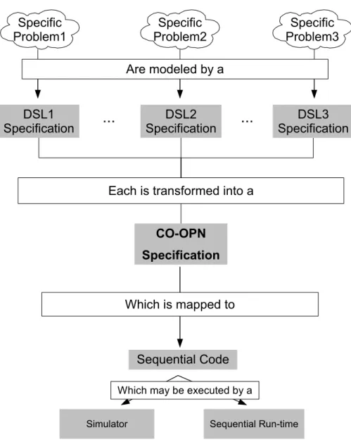
Figure 1.2 illustrates how DSLs are used to express specific problems. Modeled problems form
what is termed aSpecificationand this specification may be transformed into another
specifica-tion which follows the CO-OPN syntax and semantics. The CO-OPN code is then compiled to sequential Java code, which can be executed either in the Step Simulator or in the Sequential Run-Time.
For instance, (H)ALL modeled interfaces comprised of multiple components, each designed for receiving critical sensor data would fit nicely in an architecture where there is a thread per such component, since in that way the interface could independently receive, information from all sensors, even if they are simultaneously signaling. This ability to receive data with no delays is a major issue for Critical Control Systems.
Nowadays, CO-OPN’s generates sequential thread unsafe code. Thus, in order to avoid concurrency problems, its parallel specifications are limited to behavioral analysis through a simulator. This severe execution limitation would prevent such (H)ALL interfaces from receiv-ing simultaneous data from different sources, creatreceiv-ing execution delays on a Critical Control System.
CO-OPN employs a modular code generation approach. This code generation approach is based in allowing the use of multiple generators in order to provide multiple code generation techniques for each CO-OPN source module type.
The definition of a Parallel Run-Time that would manage all execution details, along with CO-OPN’s expressivity to deal with intricate implementation details of the interactions be-tween system entities (like concurrency control), would extend CO-OPN’s applications and offer a safe platform to develop and execute parallel software.
1. INTRODUCTION 1.2. Problem Statement and Goals
Simulator Sequential Run-time
...
...
DSL1 Specification
CO-OPN
Specification
Sequential Code Each is transformed into a
Which is mapped to
Which may be executed by a DSL2
Specification
DSL3 Specification Specific
Problem1
Specific Problem2
Specific Problem3
Are modeled by a
1. INTRODUCTION 1.3. Contributions of this Dissertation
to allow the developer to physical distribute CO-OPN specifications. In order to tackle this problem a mechanism to handle distribution must be designed and implemented.
1.3
Contributions of this Dissertation
The purpose of this work is to provide CO-OPN with a Parallel Run-Time. The new run-time must assure that interactions between concurrent entities are done correctly, and that it prevents contention issues arising from simultaneous access to the same resource.
Given that CO-OPN is a higher level language and its specifications are not focused on the details of the implementation, the generated code can target any architecture. A good balance is using concurrent components which interact through remote procedure calls. This mapping does not only allow for the execution of concurrent specifications in distinct physical machines but also in tightly coupled architectures, assuming that they have a TCP/IP stack.
Clarifying and summarizing, the main contributions of this dissertation are:
• Definition of a concurrent execution policy which respects CO-OPN semantics— The new
pol-icy combines multi-threading with synchronization mechanisms in order to insure CO-OPN semantics;
• Definition of a architectural language named CO-OPNArch— This language allows the
devel-oper to specify the physical location of CO-OPN entities and therefore a true distributed system can be deployed, developed from CO-OPN sources;
• The transformation of CO-OPN specifications into Java sources that respect the proposed
concur-rent execution policy— The modular code generation approach allowed the development
of an efficient and modular Parallel code generator which transforms CO-OPN sources into Java sources ready to be executed by the above policy rules;
• Development of a Parallel Run-Time to support concurrent execution of CO-OPN specifications
— The new Parallel Run-Time possesses mechanisms to assure that the generated code for CO-OPN specifications is successfully executed and respects the execution policy;
• Parallel Run-Time performance evaluation and comparison with the Sequential Run-Time— This
dissertation also throughly tested the Parallel Run-Time performance and compared it to the Sequential Run-Time execution results.
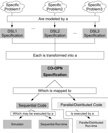
Figure 1.2 highlights the focus of this work and what are its contributions. The sequential code generator might still be used for other purposes, such as producing code for simulation.
1.4
Document Outline
1. INTRODUCTION 1.4. Document Outline
Simulator Sequential Run-time
CO-OPN
Specification
Paralle/Distributed Run-time
Sequential Code Parallel/Distributed Code
Each is transformed into a
Which is mapped to
Which may be executed by a Is executed by a
...
...
DSL1 Specification
DSL2 Specification
DSL3 Specification Specific
Problem1
Specific Problem2
Specific Problem3
Are modeled by a
1. INTRODUCTION 1.4. Document Outline
• Chapter Oneintroduced the context for the problem under study and explained lightly
how it will be solved;
• Chapter Twointroduces the CO-OPN language;
• Chapter Threedepicts all the related work needed to tackle the presented problem;
• Chapter Fourdescribes with more detail the proposed solution;
• Chapter Fivereports one implementation that follows the proposed solution;
• Chapter Six presents a use case example to evaluate the implementation described in
Chapter 5. The implementation performance is compared to the Sequential Run-Time performance.
• Chapter Seven summarizes the results of this dissertation and describes lightly some
2
Concurrent Object-Oriented Petri Nets
(CO-OPN)
Concurrent Object-Oriented Petri Nets [BBG97] is a formal language whose purpose is to model large concurrent systems. It is based on three formalisms, that are combined in or-der to define CO-OPN syntax and semantic. Besides the unor-derlying formalisms, CO-OPN also adopted the object-oriented design.
There are three components in this language: (1) Abstract Data Types (ADTs); (2) Classes; and, (3) Contexts. Each reflect one of the underlying formalisms.
2.1
CO-OPN Underlying Formalisms
CO-OPN is based on three underlying formalisms [CB01]: (1) Petri-Nets;(2) Algebraic
specifi-cations; and, (3)Idealized Workers, Idealized Managerscoordination model. The first and second
paradigm are combined in a way similar to algebraic nets [Rei91].
2.1.1 Petri-Nets
Petri-Nets [APR08] are graphical and mathematical modeling tools, used to describe discrete distributed systems. They are comprised of places, transitions and arcs.
There are two types of arcs: input and output. The former connect places with transitions and the latter transitions with places [Zim].
Places can contain tokens, and their number and type define the current state of a modeled system, also called marking.
2. CONCURRENTOBJECT-ORIENTEDPETRINETS(CO-OPN) 2.1. CO-OPN Underlying Formalisms
When the transition fires, it removes tokens from some of its input places and adds some tokens to some of its output places. The number of tokens removed/added depends on the cardinality of each arc. Preconditions are satisfied if the required tokens are available in the input places.
Places, tokens and arcs are used to represent a Petri-Net as a bipartite oriented graph, how-ever as a mathematical tool it is possible to set up state equations, algebraic equations, and other mathematical models governing the behavior of systems.
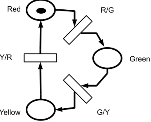
Figure 2.1 is a Petri-Net model of a traffic light.
Figure 2.1: An example of a Petri-Net
In this example there are three Places, one for each light, and three transitions. Placesare
represented by hollow elipses, transitions by hollow rectangles. As the only token of the system
is in the Red Place, the active traffic light is the red. Events that trigger transitions are not
represented, but as regular traffic lights, a timer would be the most likely trigger.
2.1.2 Algebraic Specifications — Order Sorted Algebra
Order Sorted Algebra (OSA) [Gog92] is a generalization ofMany Sorted Algebra, obtained by
having a partially ordered set of sorts rather than merely a set . There are several variants of order sorted algebras, and some relationships between these are known [GD94].
OSA main motivation is to provide a better way of treating errors in abstract data types and the use of subsorts [Gog92] can greatly speedup certain theorem proving problems [GD94].
2.1.3 Idealized Workers Idealized Managers Model (IWIMM)
IWIM is a generic model of communication to deal with the concurrency of cooperation among any number of entities that comprise a parallel application [Arb96].
The properties that characterize this model are:
• Compositionality. Which it inherits from data-flow model;
• Anonymous communication. Receivers do not specify the source of the messages they
2. CONCURRENTOBJECT-ORIENTEDPETRINETS(CO-OPN) 2.2. CO-OPN Components
• Separation of concerns. Separates the communication from the computational tasks.
2.2
CO-OPN Components
Each of the paradigms, on which CO-OPN specification language is based, is represented by a different kind of source module: Abstract Data Types, Classes and Contexts, respectively.
2.2.1 Abstract Data Types (ADTs)
Abstract Data Types define data structures and their operations [CB01]. Each ADT may define zero or more of the following elements:
• Sorts, or names, of types;
• Generators, used to build values of a given sort;
• Functionsthat manipulate values;
• Axiomsthat define functions and generators.
Listing 2.2.1 exhibits an example of an ADT specified in CO-OPN.
Listing 2.1: Specification of an ADT
1 Adt Message ; 2 I n t e r f a c e
3 S o r t message ; 4 Generators
5 ack −> message ;
6 f a i l −> message ;
7 End Message ;
Line one declares the name of the ADT (i.e.,“Message”). The data type itself is declared in
line three. It is present in theInterfacefield in order to be used by outside entities. Lines five
and six define which values are allowed for themessagedata type (i.e., “ack” and “fail”). This
ADT does not have anyfunctionsover its values.
2.2.2 Classes
A Class module describes a collection of objects with the same structure, by means of an en-capsulated algebraic net. CO-OPN objects—instantiation of Classes—own an internal state and provide a set of services to the exterior environment.The only way to interact with an object is by requesting its services, therefore its internal state is never accessed directly by other enti-ties [CB01].
A Class specification consists of:
2. CONCURRENTOBJECT-ORIENTEDPETRINETS(CO-OPN) 2.2. CO-OPN Components
• Services, that may be internal, when they are not accessible from the exterior, or
other-wise public;
• A set of Places, that define the state of the Class instances. Places are multi-sets of
alge-braic values;
• The initial values for Places, also called the initial marking;
• A set of behavioral formulas which describe the properties of public and internal
ser-vices.
Both the external and internal services may assume two forms: (1) methods; or, (2) gates. The first kind is an input service while the second is an output service [CHA04].
Class Example
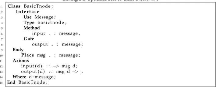
Figure 2.2 is a graphical representation for a simple entity namedBasicTnode, that can be seen
as a node of a network. This entity receives messages and holds them. When a request arrives, the entity forwards one of the hold messages.
Figure 2.2: Outline of theBasicTnode
Figure 2.2.2 is a possible mapping to CO-OPN of the entity presented in figure 2.2. The
entity is translated into aClassthat uses the Abstract Data Type defined in Figure 2.2.1 in order
to represent the messages that are saved and forwarded.
Listing 2.2: Specification of ClassBasicTnode
1 Class BasicTnode ; 2 I n t e r f a c e
3 Use Message ;
4 Type b a s i c t n o d e ;
5 Method
6 input : message ,
7 Gate
8 output : message ;
9 Body
10 P l a c e msg : message ; 11 Axioms
12 input ( d ) : : −> msg d ;
13 output ( d ) : : msg d −> ;
2. CONCURRENTOBJECT-ORIENTEDPETRINETS(CO-OPN) 2.2. CO-OPN Components
In theInterfacefield,BasicTNode’s both public services are declared, just like it is done in a
Java Interface. External module dependencies are requested in theUsenode.
The presentedClasshas onePlace, namedmsg, whose purpose is to save tokens typed
mes-sage. ThisPlaceis the repository used by the Object to store incoming messages and to retrieve
messages whenever some other entity prompt the Object to do it.
Service Definition
TheAxiomsfield of Listing 2.2.2 is where the Classes’ services are defined.
CO-OPN captures the abstract concurrent behavior of each modeled entity with the con-currency granularity associated to service invocations rather than to objects. Hence, a set of service calls may be concurrently performed on the same object.
The services may possess a set of operations over any number of object’s internal Places.
These operations are classified according to the type of access toPlaces:
• Pre conditions. Retrieval tokens from any number ofPlaces. The operations may specify
exactly which tokens are required;
• Test conditions. These operations check for the existence of tokens in the designated
Places. Again, the operations may define which tokens it requires;
• Post conditions. The purpose of these operations is to modify the object marking by
adding tokens toPlaces.
Pre and Test conditions are evaluated before Post conditions and may fail if:
• The needed tokens are not present in the designatedPlaces;or,
• One of the targetPlacesdoes not contain any tokens.
Post conditions never fail. Therefore, fromPlaces’point of view, a successfully service
exe-cution is purely dependent on its pre and test conditions success.
Some of these operations are visible in theClasspresented in Listing 2.2.2. Theinputmethod
has one post condition,msg d, which adds one objectdof typemessageto the placemsg. While
outputgate has one pre condition,msg d, whose purpose is to remove amessagefrom placemsg.
Despite test conditions are not present in the example, their syntax is as follows:place token –>
place token. Test conditions syntax is similar to merge the syntax of a pre and a post condition.
At last, as theAxiomsfield define the behavior of theClass, besides containing operations
overPlaces, the services may also contain synchronizations with other accessible services. A
service may define complex synchronization expressions which are composed by the following synchronization operators:
Relating to the examples present in the table above, the semantic of the operators is defined as:
2. CONCURRENTOBJECT-ORIENTEDPETRINETS(CO-OPN) 2.2. CO-OPN Components
Name Syntax Example
Sequence .. serviceAxiom :: service1 .. service2
Simultaneity / / serviceAxiom :: service1 // service2
Alternative + serviceAxiom :: service1 + service2
With None serviceAxiom :: service1
Table 2.1: Synchronization Operators
– service1fails, the synchronization expression fails without callingservice2;
– service2fails, service1post conditions must be undone and the synchronization
ex-pression fails.
• Simultaneity. Service1andservice2must be executed simultaneously. CO-OPN’s notion
of simultaneity refers that both services have access to the same system state, and there-fore their pre/test conditions must not race for the same set of tokens;
• Alternative. At least service1 or service2must be executed successfully in order for the
synchronization expression to be considered a success.
• With.Service1is the only service to be requested and it must have success.
Despite of being presented one by one, all but theWithoperator, may be combined to form
complex synchronization expressions, e.g.,axiomService :: (service1 // service2) + (service1 ..
service2).
At last, besides having pre,test, synchronizations with other services and post conditions, a service may also have conditions or guards over any number of its arguments.
Summarizing, a service is said to be executed successfully when:
• Conditions or guards over arguments of the object’s service are satisfied;
• All the service’s pre and test conditions succeed;
• All synchronizations occur as specified by the synchronization expression;
• Every post condition is completed.
2.2.3 Contexts
Context form what is called theCoordination Layerof CO-OPN, which is, as introduced before,
based in the IWIN model, suited for the formal coordination of object-oriented systems.
Re-calling that IWIN stands forIdealized Workers Idealized Managers,Contextsdefine theManagers,
while Classes define theWorkers [BB97].
2. CONCURRENTOBJECT-ORIENTEDPETRINETS(CO-OPN) 2.2. CO-OPN Components
In addition to object inclusion, Contexts may have, likewise Classes,MethodsandGates, but
notPlaces. All the encapsulated entities become invisible to theContext’soutside environment
and may only be accessed through public services that theContextoffers.
Object Mobility
Mobility is not available in the current implementation of CO-OPN, however in [CHA04] there are some ideas on how these concept should be implemented. These ideas are depicted bellow. A CO-OPN object and its identifier can be considered separately. An object is always en-capsulated by a context, however its identifier may exist in several.
Object mobility is attained by allowingContextsto manage references to objects, either local
or external to a givenContext. The classical Proxy mechanism was suggested in order to obtain
an homogeneous access to objects. This mechanism, along with aKnown Objects Table, would
forward synchronizations requests to the real objects.
Context Example
To shed some light onContextusage, the example of Figure 2.2.2 will be continued in Figure
2.3.
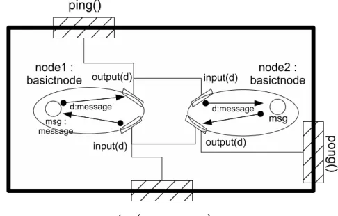
Figure 2.3: A CO-OPN Context
ThisContexthas three public methods and encapsulates two objects,node1andnode2. The
interactions between these two objects are also defined by theContext.
The public method, namedping, which is synchronized with thenode1’s outputGate. This
synchronization triggers the synchronization betweennode1’s output Gate and node2’s input
2. CONCURRENTOBJECT-ORIENTEDPETRINETS(CO-OPN) 2.3. From CO-OPN to Java
1 Context PingPong ; 2 I n t e r f a c e
3 Use
4 Message ;
5 Methods
6 ping ;
7 pong ;
8 setup : message
9 Body
10 Use
11 BasicTNode ;
12 Objects
13 node1 : b a s i c t n o d e ; 14 node2 : b a s i c t n o d e ;
15 Axioms
16 ping With node1 . output m;
17 pong With node2 . output m;
18
19 node1 . output m With node2 . input m; 20 node2 . output m With node1 . input m; 21
22 setup m With node1 . input m + node2 . input m;
23 Where
24 m : message ;
25 End PingPong ;
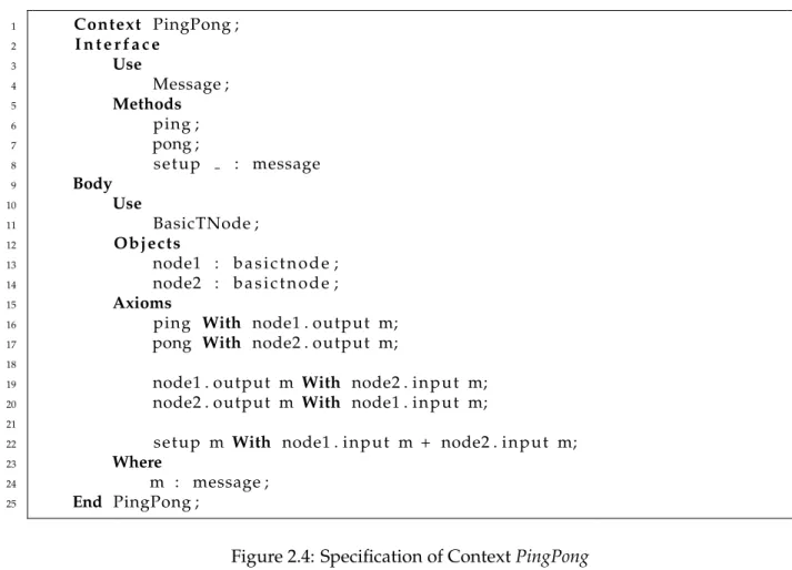
Figure 2.4: Specification of ContextPingPong
The pongmethod, does the opposite by triggering thenode2’soutputGate, which is linked
with thenode1’sinputmethod.
Context’s third and last public method,setup, supplies the “ping-pong” entities with a
mes-sage to be moved around.
ThisContexttranslation to CO-OPN is present in Listing 2.4. TheContextwas named
Ping-Pongsince the interactions between the two encapsulated objects are similar toPong, one of the
earliest arcade video games.
All three methods are declared in the Context’s interface so they can be called by an
out-side entity. PingandPongmethods translation is straight forward and makes use of theWith
operator.
On the other hand,setupresorts to the alternative operator, which states that at least one of
the nodes will get the message. The axioms present in lines 19 and 20 define the interactions
between both nodesoutputandinputservices.
2.3
From CO-OPN to Java
2. CONCURRENTOBJECT-ORIENTEDPETRINETS(CO-OPN) 2.4. Simulator and Sequential Run-Time
• ADTs. The process of converting ADTs to Java can be divided in two related sub-problems [CHA04]:
how to represent values and how to implement functions.
Each ADT sort is transformed into a Java class, while functions are firstly transformed in rewrite systems [?] and then to Java methods;
• Classes. The object-oriented structure of CO-OPN is maintained in the generated code.
Classes and their methods are represented by Java classes and methods, which contain private members and whose purpose is to encapsulate objects’ state. Gates do not have an immediate equivalence in Java, therefore they were implemented using the notion of a Java event: each is represented by an event with the same name.
Axioms that define a method are generated inside the corresponding Java method, while axioms which define connections between gates and methods are generated in event han-dlers of those gates, represented as inner classes;
• Contexts. Likewise classes, each CO-OPN Context produces a Java class and methods.
As these coordinator entities may encapsulate other entities of the specification, some of their private members are pointers to the encapsulated entities.
2.4
Simulator and Sequential Run-Time
Both CO-OPN’s run-times, are described as “sequential ordered pseudo-resolution”, because all the synchronizations between objects are executed sequentially and with the same order— left side followed by the right side of the statement—, it supports backtracking and partial unification of variables, common in logical programming languages like Prolog [CHA04].
2.4.1 Logical Instants
In order to sequentially execute a concurrent system, CO-OPN introduces the concept oflogical
instants. Every object or token in CO-OPN is timestamped with acreationandlast uselogical
instant. Even the synchronization requests have a logical time, providing means to track exactly at what “time” they should be executed [CHA04].
Logical instants are consistently represented in a tree like structure, where nodes are logical instants and the root is the initial instant. Each instant can only be target of a subdivision at most one time, thus the tree of instant is binary.
Instants are internally represented by aCoopnTransactionclass instance, which, besides
iden-tifying an instant, it can also abort the division of instants or freeze it, by resorting to transaction
related methodscommitandabort.
An instant is divided to represent synchronization policies, so each synchronization opera-tor has its own corresponding instant division. Correspondences can be seen in Table 2.2.
As an example, Figure 2.5 illustrates an acceptable instant division tree representation.
Actions with time stampSeq1are supposed to be performed logically beforeSeq2.Seq2Par1
2. CONCURRENTOBJECT-ORIENTEDPETRINETS(CO-OPN) 2.4. Simulator and Sequential Run-Time
Synchronization Operator Type of Instant Subdivision
Alternative Alternative
Sequence Sequential
Simultaneity Simultaneous
With Included sub-instant
Table 2.2: Instant Division vs Synchronization Policies
Figure 2.5: Instant Representation Tree
identify logical times which may be used by two distinct alternative operations.
CO-OPN’s Sequential Run-Time serializes concurrent behaviors. Thus, there is a part of system state which is produced by sequential execution that can not be consumed, because the
producer synchronization was executing logically in parallel with the consumer, e.g.,service ::
produce // consume. Theproduceservice will be requested beforeconsume, although produce’s
generated tokens may not be used by the consume service). Even if the state already exists,
sometimes it cannot be accessed too due to simultaneous access of another operation.
By resorting to logical timestamps of conflicting operations, previous access conflicts are solved, since a token belongs to earlier instant if it has a creation time stamp that logically precedes the instant at which an operation tries to access that token. Parallel accesses follow the same line of thought, however when a synchronization has to access a token, it must also check the last use time of that token and if the token is being accessed at a parallel logical time, then only one of the accesses can succeed. In the next section some ideas are presented to clarified this issue.
2.4.2 Representing Synchronization Policies
2. CONCURRENTOBJECT-ORIENTEDPETRINETS(CO-OPN) 2.4. Simulator and Sequential Run-Time
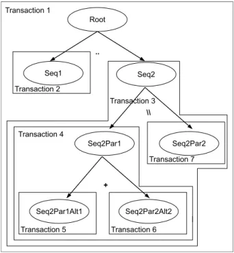
Complex synchronizations are grouped like nested transactions. As an example, every leaf node in the tree illustrated in Figure 2.5, would correspond to an instant at which an operation should be executed. Therefore, For every operation a transaction will be created, resulting in seven distinct transactions, which are visible in Figure 2.6
Figure 2.6: Instant Subdivision Tree and Nested Transactions
The root of the synchronization tree is encapsulated in one transaction and for each root’s sub branch a transaction is also created ( transaction 2 and transaction 3). This transaction creation scheme is repeated for each sub-branch.
Concurrent Accesses to Places
Places of objects are likely to be accessed at the same logical time. Therefore, CO-OPN must en-force policies to disallow inconsistent accesses to stored tokens. Access policies are represented in Tables 2.3 and 2.4, where cells are identified using a (row,column) fashion.
Table 2.3 shows CO-OPN’s simultaneous access policy. Both column and row operations try to use the same token.
Type of Access
Type of Access Pre condition Post condition Test operation
Pre condition No Yes No
Post condition No Yes Yes
Test operation No Yes Yes
Table 2.3: Simultaneous Accesses to Places
Simultaneous operations will succeed most of the times, except when:
2. CONCURRENTOBJECT-ORIENTEDPETRINETS(CO-OPN) 2.4. Simulator and Sequential Run-Time
• One tries to check for the existence of the token while the other removes it, e.g., cells (1,3)
and (3,1);
• One pre condition over a token created by a post condition at a simultaneous time, e.g.,
cell (2,1).
Table 2.4 is similar to table 2.3, however row operations precede column operations: i.e.,
cell (2,3) should be read as ”Post condition”sequence“Test operation”.
Type of Access
Type of Access Pre condition Post condition Test operation
Pre condition No Yes No
Post condition Yes Yes Yes
Test operation Yes Yes Yes
Table 2.4: Sequential Accesses to Places
Through a careful analysis of Table 2.4, the sequential policies are the following:
• A token cannot be removed twice, e.g. cell (1,1);
• A token cannot be removed and later be used in a test operation, e.g. cell (1,3);
• Multiple sequential test operations over the same token are valid, e.g. cell (3,3);
2.4.3 CO-OPN Non-Determinism and Backtracking
There are two sources of non-determinism to consider [CB01]: non-deterministic choice be-tween possible matching values in Places; and, bebe-tween alternative transitions.
Handling Non-Determinism in Places
This source of non-determinism was implemented by applying the Prolog execution model
to Java [CHA04], but again, CoopnTransactionholds a very important role. Prolog execution
model is present in Figure 2.7
Prolog provides methods with two entry points: “Enter” and “Redo”; and, two exit points: “Exit” and “Fail”. “Enter” followed by “Exit” shows the standard Java method behavior. The method is called and returns regularly. “Redo” re-executes the method demanding a new solu-tion — a set of tokens that satisfy the pre-, test-condisolu-tions —, which is different from the ones already returned, and finally “Fail” signals that there are no more solutions available.
2. CONCURRENTOBJECT-ORIENTEDPETRINETS(CO-OPN) 2.4. Simulator and Sequential Run-Time
In both Run-Times, distinction between “Enter” and “Redo” modes is done using a
Coopn-Transactionobject that acts as the transaction identifier. If the method is called more than once
with the same instant identifier then it enters the second mode otherwise it enters the first. The
“Fail” mode is signaled through the Java exceptionCoopnMethodNotFirableException.
Handling Non-determinism in Alternative Transitions
The supported synchronization operators were introduced and explained in Section 2.2.2. The
alternativeoperator allows the developer to define alternative synchronization branches. The
choice of which branch should be tested is non-deterministic.
Although, CO-OPN has another way to define alternative transitions. By defining multiple axioms for the same service, the developer also creates alternative transitions. Recalling the
Ping-Pongexample of Listing 2.4, thesetupservice of theContextcould go from
setup m With node1.input m + node2.input m;
to
setup m With node1.input m;
setup m With node2.input m;
The Prolog execution model is also applied to alternative transitions. Whenever a service is called in “Redo” mode, besides searching for more solutions in the already tested transition, CO-OPN also tests alternative transitions for the same service. But before doing that, the Run-Time must undo previously made modifications to object’s state.
To achieve such transaction-like behavior, aStateobject is used to save local variables and
theCoopnTransaction object, which holds the instant identifier, is used so the Run-Time may
3
Related Work
This chapter introduces and discusses related work that is relevant for this dissertation. Section 3.1 briefly introduces Domain Specific Modeling and Languages so the reader may acquire some knowledge in this field.
Section 3.2 studies the Message Passing model, and more specifically the Remote Procedure Call (RPC). The focus is on the Message Passing mode, since as was discussed in Section 2, CO-OPN entities interact through service synchronization.
At last, Section 3.3 addresses concurrency control mechanisms. This section is relevant as it introduces ways to prevent inconsistent results due to concurrent accesses to the same data.
3.1
Domain Specific Modelling (DSM)
Raising the level of abstraction was always a way to improve productivity [KT08]. Advances in tradicional programming languages and modeling languages are contributing little to that goal, at least if compared to the productivity boost accomplished by changing from Assembly to third generation languages (3GLs), like FORTRAN and C. Using 3GLs, one can express the same program semantic by writing just one line instead of the several Assembly lines required otherwise [KT08].
Listings 3.1 and 3.2 illustrate how difficult it can be to write a While loop in Assembly
comparing to write an equivalent loop in the C programming language.
3.1.1 DSM Goals
3. RELATEDWORK 3.1. Domain Specific Modelling (DSM)
Listing 3.1:Whileloop in C
1 i n t x = 5 ; 2 while ( x > 0 )
3 x−−;
Listing 3.2:Whileloop in Assembly
1 . . . .
2 mov COUNTER, 5
3 WHILE cmp COUNTER, 0
4 j l e END WHILE
5 mov eax , COUNTER
6 sub eax , 1
7 mov COUNTER, eax
8 jmp WHILE
9 COUNTER dw 0
10 END WHILE . . . .
DSM has two main purposes [KT08]. First, by specifying the solution in a language that uses problem domain terminology and rules, it raises the abstraction level. Second, it offers tools for rapid prototyping which automatically generate code in a chosen programming lan-guage.
An extensive automation of development may be achieved since the modeling language, code generator and framework code must uniquely fit the requirements of a narrow application domain.
3.1.2 Domain Specific Languages (DSLs)
A DSL is a programming language whose scope is a particular domain. They are classified as
forth generation languages, for they describe whatneedsto be done, rather thanhowit should
be done, like 3GLs do [DSL]. A well known example is SQL, used for database queries.
Such languages reduce the conceptual distance between the problem space and the syntax used to express it. This abstraction leads to simpler, easier and more reliable programs and programming techniques. Reliability comes from the ability to validate and optimize specifica-tions at domain level, rather than using debuggers and tests sets. By using domain terminology, DSLs’ specifications become concise and self-documented to a wide extent, partially relieving the developer from producing documentation and therefore, allowing him/her to focus in code production tasks.
DSLs can be transformed directly tobytecodeor machine code, which is ready to be executed
by the processor. Nevertheless, to aid the development of an automatic code generator, they can also be transformed to some other high level language with an already implemented machine
code orbytecodecompiler.
3. RELATEDWORK 3.2. Communication in Concurrent Systems
3.2
Communication in Concurrent Systems
Communication in concurrent systems is used mainly to synchronized the different system en-tities and to share data amongst those system enen-tities. This section will introduce the Message Passing model and a communication pattern named Remote Procedure Call that is supported by that model.
3.2.1 Message Passing
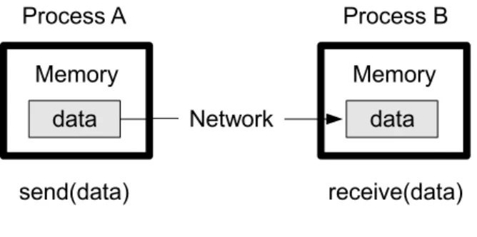
In the Message Passing model, processes communicate via messages over communication channels, and each channel provides a bidirectional connection. Therefore, it is defined as a set of processes, which only have local memory, and the transfer of data requires cooperative operations to be performed by each process [CD01]. Figure 2.10 illustrates a simple message passing system, comprised of two processes which interact through the cooperative operations
send(data)andreceive(data).
Figure 3.1: A simple message passing example
The topology of this model is defined by the pattern of connections provided by channels. It can be represented by an undirected graph in which each node describes a process and an edge is present whenever a channel exists between two nodes. These connections can the statically created or dynamically during the system progress.
Messages can be sent or received obeying to two different disciplines, either blocking or non-blocking. The first discipline requires that both the sender and receiver process waits until the message is successfully sent or received. The latter states that the routines for sending and receiving may return right after the call, having the calling process to check if the message has been correctly handled.
Examples of message passing libraries include public domain packages that do not target a specific architecture (e.g., PVM [PVM], PARMACS [PAR], MPI [MPI], etc) as well as machine dependent vendor implementations (e.g., ACL [JPH95], HP-MPI [HP-], etc). The common com-ponents of message passing libraries include:
1. Process management routines e.g., initialize and finalize processes, determine number
of processes and process identifiers;
2. Point-to-point communication routinese.g., basic sends and receives between any two
3. RELATEDWORK 3.2. Communication in Concurrent Systems
3. Process group/collective communication routinese.g., broadcast/gather/scatter
opera-tions amongst a set of processes, synchronization of processes.
3.2.2 Remote Procedure Call (RPC)
The Remote Procedure Call concept was first suggested by Birrel and Nelson in [BN83], as an inter-process communication technology that allows processes to execute a method in another address space. All the details for the remote synchronization are hidden from the programmer.
The description of the RPC model is provided by Figure 3.2.
Figure 3.2: Remote Procedure Call model
There are three main components: the client application, the network and the server
appli-cation. The client application is comprised by theclientand by the clientstub, while the server
application is composed by the server and by the Skeleton, which is the server application’s
stub. TheClientand theServercomponents are where the procedure is required and provided,
respectively. TheNetworkhandles communication between both stubs.
The existence of a visible distinction between the local code and the stubs, which deal with the remote interaction details, turns RPC into a transparent mechanism [TAN95].
The client stub, packs the parameters of the procedure, sends them in a message to the server and blocks itself until the reply from the server is received. The server stub is bound with the server, typically will be blocked waiting for incoming messages. Upon receiving a message, unpacks the parameters from it and the calls the server procedure. From the server’s perspective, the method was called directly by the client. The server executes the procedure and returns control to the server stub, which packs the results in a message and sends it to the client.
The client stub receives the message containing the result of the computation, unpacks it, copies the result to the client local buffer and the control is given to the client.
Figure 3.3 represents a simple example, which omits both stubs. “P1” calls “a” method on “P2”, whom executes “a” and replies the result back to “P1”. As referred above, none of the processes are aware of how synchronizations are handled.
Java Remote Method Invocation (JMRI)
3. RELATEDWORK 3.2. Communication in Concurrent Systems
Figure 3.3: Remote Procedure Call example
to marshal — write and send — and unmarshal — read — parameters and does not truncate types, supporting true object-oriented polymorphism.
The homogeneous environment of the Java virtual machine (JVM) is assumed, therefore the system can take advantage of the Java platform’s object model whenever possible.
Since remote method invocation on the same remote object may execute concurrently, the specification using this technology needs to ensure thread-safeness.
In JRMI, the network component of the RPC model uses a wire level protocol called Java Remote Method Protocol (JRMP) which runs on top of TCP/IP and is used for looking up and referencing remote objects. By using TCP/IP connections, it provides basic connectivity as well as some firewall penetration strategies. Even if the two JVMs are running on the same physical machine, the TPC/IP stack is used.
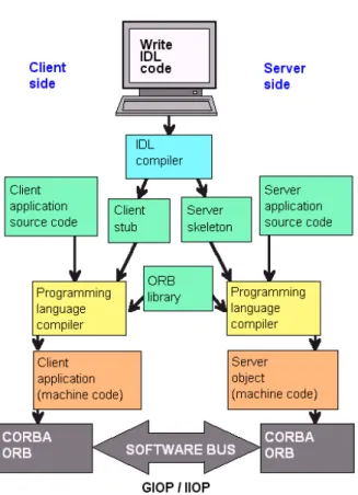
Common Object Request Broker Architecture (CORBA)
CORBA [CD01] is a standard defined by the Object Management Group, which describes an architecture for interoperability of distributed objects through remote method invocation.
One of its components is termed Interface Definition Language (IDL), whose purpose is to
declare interfaces for the objects, which guarantees interoperability, disregarding the language of the caller or how the callee is implemented. Existing standard mappings translate IDL to Ada, C++, C, Java, etc.
Another important aspect of CORBA is the support for mechanisms to locate objects. These
mechanisms are encapsulated in the Object Request Broker component which assures correct
method invocation and posterior result deliver to the caller object.
Figure 3.4 shows the steps that have to be taken, in order to produce two specifications
which communicate with CORBA. It is also present theSoftware Busthat represents theNetwork
component of the RPC model.
CORBA is a powerful architecture, on the other hand, it is time consuming and not is straight forward to develop a system using it.
Discussion: JMRI vs. CORBA
A study of these two technologies shows some degree of functional overlapping, though each has it strengths that outshine the other for particular tasks.
3. RELATEDWORK 3.2. Communication in Concurrent Systems
3. RELATEDWORK 3.3. Concurrency Control for Management of Shared Data Contention
• Cross-Platform. JRMI is dependent on Java implementations, and therefore, to interact
with legacy systems, a Java adapter is required. CORBA specifications may be imple-mented in different languages and executed on different platforms, including Java.
• One Interface, Many Implementations. Both technologies allow for the creation of an
interface and multiple implementations of that interface. In CORBA interfaces are written in IDL, whilst in JRMI they are written in Java.
• Object Mobility. JRMI supports sharing of objects, using object serialization. CORBA
does not.
• Easy To Master. CORBA implementations require usually a few more steps than JRMI
ones.
CORBA is a rich, extensive family of standards and interfaces, and delving into the de-tails of these interfaces is sometimes excessive for the task at hand. In contrast, JRMI can be relatively easier to master without neglecting its functionality.
JRMI is suitable to meet this work requirements and for that, it was the chosen RPC imple-mentation.
3.3
Concurrency Control for Management of Shared Data Contention
Concurrency Control holds the responsibility for ensuring correct results after concurrent op-erations. Besides correctness, it is also expected for the results to be achieved as quickly as possible.
This section introduces some mechanisms to control concurrent accesses to shared data,
andSpecifications Models as ways to test design decisions without producing an actual
imple-mentation.
3.3.1 Execution Models and Support
This section presents some of the existing mechanisms which allow sharing of resources,
with-out compromising their consistency. Mechanisms are said to beblockingwhenever a thread is
blocked while waiting for a given resource. Motivation fornonblockingtechniques comes from
their immunity to large, unpredictable delays in thread progress often linked with the previous mechanism [MS95].
Execution Models
Execution models may be classified in two main groups: pessimistic or optimistic. In a
pes-simistic schemeresources are locked early in the data-access and are not released until the access
is performed. While theoptimistic schemeallows accesses to shared resources without any
3. RELATEDWORK 3.3. Concurrency Control for Management of Shared Data Contention
Deciding whether or not to use optimistic concurrency depends on the type of system, or operation. Optimistic concurrency control is employed when conflicting accesses are expected to be infrequent, the opposite follows for the pessimistic scheme.
Blocking Mutual Exclusion
Mutual exclusion is perhaps the most prevalent form of coordination [HS08]. This mecha-nism is used to prevent simultaneous accesses to a common resource and such goal is achieve through Critical Sections. A Critical Section is a block of code which is typically surrounded by Locks, however there are several different solutions guarantee exclusive access to the protected code.
A model of a Critical Section is shown in listing 3.3. It is present that the access to the resource is protected by any mutual exclusion mechanism.
Listing 3.3: Mutual Exclusion Region
1 G e t E x c l u s i v e A c c e s s
2 A c c e s s P r o t e c t e d R e s o u r c e 3 R e l e a s e E x c l u s i v e A c c e s s
Locks Locks are synchronization mechanisms to control simultaneous accesses to shared
re-sources. They provide two main methods,lockandunlock. The first acquires exclusive access
to the resource while the latter releases it.
These mechanisms typically require hardware support for efficient implementation, since it allows a single process to test if the lock is free, and if so, acquire the lock in a single atomic operation.
A good locking algorithm should satisfy the following properties [HS08]:
• Mutual Exclusion. Critical Sections of different threads do not overlap;
• Freedom from deadlock. One of the threads will eventually acquire the lock;
• Freedom from starvation. Every thread will ultimately acquire the lock.
Locks are however associated with several disadvantages [DFL02]:
• Priority Inversion. Occurs when a higher-priority process requires a lock owned by a
lower-priority process;
• Convoying. Takes place when a process holding a lock is preempted by exhausting its
quantum or by some kind of interrupt. Consequently, running processes requiring the lock are unable to progress;
• Deadlock. Happens if different processes attempt acquire the same set of locks in
3. RELATEDWORK 3.3. Concurrency Control for Management of Shared Data Contention
Monitors Monitors are modules which encapsulate a shared data structure, its operations
and a private lock [HS08]. Each access to the data structure requires previous acquisition of its internal lock.
Since these modules combine data structures and synchronizations in the same package, there is no need to ensure that every access to the data structure follows a cumbersome syn-chronization protocol. If besides acquiring the lock the operation has other pre conditions that are not satisfied, threads can be suspended and resumed when pre conditions are fulfilled. Suspending threads and releasing the lock while all conditions are not satisfied is important, because otherwise no other thread could access the data structure and change its state.
To make all these ideas clearer, one can think in an application composed of two threads — a producer and a consumer —, that communicate through a shared FIFO queue. The queue and
its operations,queueandenqueue, would be packaged in amonitorwhich acts as a
synchroniza-tion agent, serializing accesses to it. If the consumer would lock the data structure and would not release it until there were elements to consume, the application would deadlock since the producer would not ever gain access to the queue and therefore no elements would be added.
Figure 3.5 shows a linked list encapsulated by a monitor. The data structure methods,
ListAdd(...) andListRem(...), are synchronized with the external methods,Add(...) andRem(...),
provided by themonitor. In order to access the list, the caller process must call the external
methods.
Figure 3.5: An example of a Monitor
This synchronization mechanism suffers from the following drawbacks [Sch00]: (1) Tightly coupling between object functionality and synchronization mechanisms; and, (2) Nested mon-itor lockout.
Item (1) relates to synchronization logic which is often closely coupled to monitors meth-ods’ functionality. Therefore it is hard to change synchronization policies without changing monitors methods’ implementation.
3. RELATEDWORK 3.3. Concurrency Control for Management of Shared Data Contention
for a signal, and another for a lock to be released. Like in a deadlock situation, there are two threads blocked, although, this problem cannot be avoided using lock ordering.
Monitors are present in all Java objects and they allow threads to implicitly serialize their
execution through method-call interfaces and coordinate their activities via explicitwait,notify
andnotifyalloperations.
Nonblocking Mutual Exclusion
Nonblocking techniques became a major break through, since they seemed to solve some of the locks’ issues. These mechanisms ensure safety while refraining mutual exclusion. However, existing techniques are rarely suitable for practical usage, given that either they are too complex to implement or impose too much memory overhead.
Nonblocking algorithms can be classified according to the kind of progress guarantee that they offer [FH07]:
• Obstruction-freedom is the weakest guarantee: A thread is only guaranteed to make
progress as long as it does not access any location concurrently with another thread. Re-quires an out of ban mechanism to prevent live lock;
• Lock-freedomadds the requirement that the system as a whole makes progress, even if
there is contention. This is sufficient to avoid live lock, although it does not guarantees of per-thread fairness.
• Wait-freedomis the strongest guarantee, since it adds the requirement that every thread
makes progress, even if it experiences contention.
The underlying core of these techniques are atomic hardware instructions, such as
compare-and-swap, which atomically updates one or more memory locations from a set of expected val-ues to a set of new valval-ues.
Performance considerations Under light to moderate contention, these techniques perform
better than their blocking counterparts, since most of the times the required hardware instruc-tions succeed at the first try. However under high contention environments, blocking mecha-nisms offer better throughput, as threads are suspended and restarted when the lock is released.
Java nonblocking API Java offers a suite of nonblocking data structures with itsjava.util.concurrent
package. Just as an example, its nonblocking stack uses the Treiber’s algorithm, which uses the
compare-and-swaphardware instruction to modify the top node of the stack [MS98].
3.3.2 Specification Models
3. RELATEDWORK 3.3. Concurrency Control for Management of Shared Data Contention
for concurrency are: PI-Calculus [MPW89], CSP [Hoa78] and Petri-Nets. The latter will be summarily introduced bellow.
There are three important properties for concurrent programs: Liveness,SafetyandFairness
[Sis99,VVK05]. The first asserts that a program execution will eventually reach a desirable state.
Safetyproperties assert that something bad never happens. The third property may be seen as a
special class ofLivenessproperties, and states that a particular choice is taken sufficiently often
provided that it is sufficiently often possible.
The introduced specification models lack the ability of executing the specifications, instead they solely serve the purpose of verifying and analyzing the generated specifications. CO-OPN, besides allowing the programmer to analyze the behavior of the specifications, also has an implemented run-time, which acts as a platform to execute CO-OPN specifications.
3.3.3 Concurrency Control Mechanisms Applicability
The required concurrency control for a parallel implementation of the CO-OPN execution model, goes through protecting data structures of each object from concurrent accesses, while
maintaining synchronization atomicity. By usingMonitors, which are present in all JAVA
4
A Parallel Run-Time for CO-OPN
A Parallel Run-Time for CO-OPN provides a parallel way to execute CO-OPN specifications, filling the execution gap in which CO-OPN was bounded.
The run-time should be able to suffice all CO-OPN requirements linked with its special semantic that makes the language so interesting. This section depicts the requirements of a parallel run-time and proposes an abstract solution ready to be implemented.
4.1
Requirements for Parallel Execution of CO-OPN Specifications
When a language execution is moved from a Sequential Run-Time into a Parallel one, it is nec-essary to fully understand the language in order to know which parts of its execution should be parallelized and which parts of the execution run-time are likely to be endangered by con-tention issues.
This section depicts the core characteristics of CO-OPN which should be tackled to build a good and robust parallel run-time.
4.1.1 Synchronization Operators Semantic
The first requirement concerns the semantic of the operators used in synchronization
expres-sions (e.g., example of a synchronization expressionleftMember SynchronizationOperator
right-Member) :
1. Sequence. This operator has a simple translation, since it only requires that the left
mem-ber is executed successfully before the right memmem-ber.
2. Alternative. Can have a translation similar to theSequenceoperator, in view of the fact
4. A PARALLELRUN-TIME FORCO-OPN 4.1. Requirements for Parallel Execution of CO-OPN Specifications
other is called if the previously member fails. The sequential run-time does not support the use of the alternative operator in synchronization expressions, but the similar behav-ior may be attained by defining multiple axioms for the same service.
3. Simultaneity states that for a synchronization to have success, both its members must
succeed at the same logical time;
4. Withdefines an included sub synchronization.
The Sequenceoperator is straight forward to support, the left member is called and if it is
successful then the right member is called. When applying theSequenceoperator one of three
cases may happen: (1) If the first member fails, then it is unnecessary to call the second; (2) If the first member succeeds and the second does not, then it is necessary to undo changes to the marking done by the first member; (3) both members succeed in the defined order, thus the synchronizations expression succeeds. Implementing this operator should be straight forward except the transactional semantics imposed by the second case.
TheAlternativeoperator may be fully supported through the definition of multiple axioms.
It would be possible to support directly the usage of the alternative operator by translating the
synchronization expression to multiple axioms. (e.g.,leftMember alternativeOperator
rightMemberwould be translated intoaxiom1 := leftMember,axiom2 := rightMember).
Support for theSimultaneityoperator requires a way for the two members of a simultaneous
synchronization expression to have access to the same system marking in order to execute their pre/test and post conditions in this system state.
At last, theWithoperator must be defined as a simple service request and therefore it should
not raise any implementation issues.
In order to jump outside of the scope of the sequential execution, the simultaneity operator may also take advantage of multi threading by encapsulating each member in its own thread. Doing this supposedly increases the level of system performance but it also implies protecting data from concurrent accesses. The next section will shed some light on how to provide such an environment.
4.1.2 Logical Execution Semantics
The use of subdivision operators enrich CO-OPN with the notion of logical time. Some events
should occur before others where some occur at the same logical instant (e.g.,Member1
Simul-taneousOperator Member2,Member1andMember2must succeed at the same logical time).
Although this notion seems rather trivial, the Sequential execution of CO-OPN required two types of management involving logical timestamps:
1. Control the access to tokens in places;