Production of TiO
2Coated Multiwall Carbon Nanotubes by the Sol-Gel Technique
Laura Angélica Ardila Rodrígueza*, Matheus Pianassolaa, Dilermando Nagle Travessaa
Received: April 26, 2017; Revised: October 01, 2017; Accepted: November 10, 2017
In recent years, efforts in developing high strength-low density materials are increasing significantly. One of the promising materials to attend this demand is the carbon nanotube (CNT), to be used mainly as a reinforcing phase in lightweight metal matrix composites (MMC). In the present work, the sol-gel technique has been employed to obtain TiO2 coating on the surface of commercial multiwall carbon
nanotubes (MWCNT). The aim of such coating is to improve the thermal stability of MWCNT in oxidize environment, which is necessary in most of MMC processing routes. Calcination in inert atmosphere was performed in order to crystallize a stable coating phase. The hybrid CNT/TiO2 nanocomposite was
characterized by X-Ray Diffractometry (XRD), Raman spectroscopy, Thermogravimetry (TGA) and Field Emission Gun - Scanning Electron Microscopy (FEG-SEM). The coating structure was observed to change from anatase to rutile, as the calcination temperature increases from 500 to 1000ºC. Results from thermogravimetric analysis showed that the samples calcined at 1000 ºC were more resistant to oxidation at high temperatures.
Keywords: Carbon nanotubes, TiO2, sol-gel, surface coating.
*e-mail: [email protected]
1. Introduction
In the last three decades, since the carbon nanotubes (CNT) were discovered, intense research efforts have been done in order to exploit their excellent mechanical properties. Particularly a Young modulus and a tensile strength of around 1 TPa1,2 and 200 GPa3, respectively, made CNT highly prone
to act as a reinforcement phase in several types of composite materials, including polymeric, ceramic and metal matrix.
Metal matrix composite materials (MMC) have being studied due to their potential produce lightweight structures for the transportation industry, mainly automotive, aeronautical and space4. The use of CNT as reinforcing phase for MMC
has been a challenge because of its high surface area and the resulting Van der Walls interactions that make difficult its dispersion5,6. Furthermore, it has been observed that CNT has low wettability by most metals, resulting in low interaction with the matrix and low potential for strengthening by load transfer mechanisms7-9.
Many authors have tried to improve CNT dispersion in metal matrix by several processing routes, as thermal spray6,10, high
energy ball milling11, friction stir processing12. In most cases,
it has been observed that the extreme processing conditions mainly related to high temperatures and stresses can damage the CNT structure13,14. CNTs are thermodynamically stable
up to 2200 ºC if no oxygen or other reactive impurities are present. However, they are quite reactive with oxygen at temperatures above 500ºC, forming carbon oxide or dioxide15.
Consequently, high temperature composite processing can lead to CNT to degrade if oxygen or reactive elements are
present. Some advanced MMCs processing routes, like spark plasma sintering16,17, involves inert gas fluxes or vacuum that
can preserve the CNT integrity. However, such processing routes are usually expensive, requiring costly equipment and gases. Furthermore, such processes are not suitable for high productivity.
Conventional processes capable of achieving high productivity, such as hot extrusion or hot rolling18,19, are
normally performed without gas protection. Other industrial scale processes like plasma spray, used for parts surface protection or repair, involve temperatures higher than the graphite boiling point (4900 ºC). Consequently sublimation of carbon nanotubes during the plasma spray forming20 can
occur. Alternatively, in the High Velocity Oxy-Fuel (HVOF) process, temperatures are lower than plasma spray, but in this case, CNTs are in close contact with the working gas, reacting with the containing oxygen21. Therefore, a large
amount of the CNTs embedded in the molten Al can be lost during HVOF spraying.
Aluminum can also react with the carbon nanotubes during the production of Al/CNT composites, even under protective atmospheres 7,22. This reaction is concentrated at
CNT surface defects and forms aluminum carbide (Al4C3).
Depending on the processing conditions, this reaction can extend to few angstroms at the metal/CNT interface or, under extreme conditions as in processes involving liquid Al, it can totally consume the CNTs23. Ci et. al 7reported
that the formation of Al4C3 at the interface can improve the
interfacial bonding to some extension. However, the Al4C3
is easily decomposed in Al(OH)3, CO2 and H2 in presence
aUniversidade Federal de São Paulo (UNIFESP), Instituto de Ciência e Tecnologia, Laboratório de
of liquid water or moisture. Park et al24 found that Al 4C3
can decompose in less than 120 h, when exposed to a wet environment, resulting in matrix to CNT interface debonding that accelerates the fatigue crack growth rates on Al/SiC composites tested in moisture environment.
In order to mitigate much of the difficulties in obtaining CNT reinforced MMC, in the present work, we propose to coat the CNT with a ceramic material 25,26, expecting to
improve their adherence with the metallic matrix, to make easier their dispersion during the composite processing and to protect the CNT from severe processing conditions and from excessive reaction with the matrix27. As a result, the unique
characteristics of CNT those make them very interesting as reinforcing phase in MMC can be fully exploited.
Manivannan et al25 employed the sol gel method in order
to coat MWCNT with zirconia, and the resulting MWCNT/ ZrO2 composite was sintered in nitrogen atmosphere at different temperatures in order improve their bonding at the interface. They observed from TGA studies that oxidation resistance of the sintered composite was improved with proper selection of sintering temperature. Inam et al 26 found that
fabricating alumina-CNT nanocomposite by atomic layer deposition (ALD) resulted in encapsulated nanotubes that provided a shielding effect against further oxidation during the composite consolidation by spark plasma sintering. The thicker alumina coating obtained by ALD, the better the CNT resistance to oxidation during subsequent sintering. Jo et al 27 coated carbon nanofibers (CNFs) with titanium
dioxide by the sol gel method, in order to improve their wettability and prevent reactions with molten aluminum matrix during the production of Al/CNF by liquid pressing process. The authors found from TGA analysis that TiO2
coated CNFs could maintained their mass up to 1000ºC in the air atmosphere without significant losses, confirming that a TiO2 coating can enhance the structural stability of CNFs
in severe environments, preventing the Al4C3 formation.
Within the context of the protection of carbon nanotubes during the production of metal/CNT composites, in the present work we describe the synthesis of a TiO2 coating formed on
the surface of multiwall carbon nanotubes (MWCNT) by the sol-gel route, using titanium tetra isopropoxide (TTIP) as a precursor. Processing parameters such as TTIP: H2O
molar ratio in the solution and MWCNT concentration are investigated and related to the quality of the obtained coating. The structure and morphology of the hybrid MWCNT/ TiO2 were investigated by X-ray diffraction (XRD), field
emission gun-scanning electron microscopy (FEG-SEM), Raman spectroscopy and thermogravimetric analysis (TGA).
2. Experimental
2.1. Materials
In this study Baytubes® C 150 P MWCNT, were used.
The MWCNT were produced by Bayer Materials
Science-Germany by the CVD process, resulting in a minimum purity level of 95%, internal and external diameters of the order of 4 and 13 nm, respectively, and length greater than 1 µm. Nitric acid 65% PA, sulfuric acid PA-ACS analytical grade, Sodium dodecyl sulphate (Synth), Ethanol 99.8% P.A, Titanium tetra isopropoxide (Aldrich), glacial acetic acid 99.8% (Neon) and Ammonium hydroxide PA (Synth) were the reagents used to functionalize and coat the MWCNT.
2.2. Carbon nanotubes functionalization
Aiming to introduce surface functional groups on the MWCNT surface that are necessary to anchor the TiO2 layer,
the MWCNT were acid treated in 60 mL of 1: 3 (v:v) of nitric acid and sulfuric acid for 6 hours under magnetic stirring. The resulting mixture was washed in deionized water and dried at 80 º C for 15 hours.
2.3. MWCNT/TiO
2nanocomposite synthesis
TiO2 coated MWCNTs were obtained by the
sol-gel method using titanium tetra isopropoxide (TTIP) as precursor. One of the problems of the sol gel technique is that it normally leads to a non-uniform coating, resulting simultaneously in some uncoated surface regions along with excessive deposits in other regions of the MWCNT surface 28. In the present work, it was employed the Gao
et.al 29 method, with modifications. The use of surfactants
as sodium dodecyl sulphate (SDS) significantly improved the dispersion of MWCNTs in aqueous solution, providing an efficient support to the TiO2 nanoparticles to growth
and attach to the MWCNTs surface via noncovalent bond. Initially, a constant mass of MWCNT was dispersed in Milli-Q water, with 2% wt. of sodium dodecyl sulphate (SDS) and sonicated for 30 min. Then 20 mL of ethanol was added to the mixture and stirred for another 30 min, forming a MWCNT suspension. In parallel, titanium tetra isopropoxide (TTIP) was mixed with 15 mL of ethanol and glacial acetic acid under stirring for 30 min, forming the TiO2
solution. Finally, the TiO2 solution was added dropwise in
the MWCNT suspension under vigorous stirring that was kept for 2 hours in order to complete the reaction. At this stage, the TTIP precursor hydrolyses in contact with the water present in the MWCNT suspension. The resulting TTIP:H2O molar ratios were 1:60, 1:220 and 1:340, and
the weight ratio of MWCNT related to the TiO2 formed was
28%. Ammonium hydroxide was added dropwise until a pH of 9 was reached, and finally 10 mL of ethanol were added to the mixture, keeping the stirring for another 30 min. The final suspension was centrifugated and washed three times in ethanol. The drying process was carried out for 15 hours at 60º C in order to obtain the powdered TiO2-coated MWCNT.
For comparison purpose, the same procedure was performed for a TTIP:H2O molar ratio of 1:220 and varying the amount
of MWCNT, resulting in two additional MWCNT to TiO2
The hybrid MWCNT/TiO2 obtained was calcined at
temperatures of 500 and 1000º C for 3 hours in an inert argon atmosphere, in order to crystallize the amorphous coating layer obtained from the sol-gel process.
2.4 Samples characterization
The TiO2-coated MWCNT were characterized by X-ray
diffraction, in order to verify the crystallinity degree of the obtained coating. A Rigaku X-ray diffractometer model Ultima IV was used, operating with Cu Kα radiation (λ = 1.54178 Å) with a voltage of 40kV and 30mA of current. Multiple detectors (fast detection mode) were used at steps of 0,01º and a speed of 5º/min, resulting in a high signal level. The microstructure was analyzed using a Tescan model Mira 3 field emission gun-scanning electron microscope (FEG-SEM). The SEM images were formed from Secondary Electrons (SE), at 2 mm of work distance and 5kV. Raman spectroscopy was recorded by a Horiba LabRAM microscope with 514 nm laser. The Raman spectra were collected using 3 accumulations in 30 seconds, in the range of 50 to 2000 cm-1. Thermal gravimetric analyzes were performed on a NETZSCH STA 449 F1 Jupiter equipment (TG-DSC / DTA) with a heating rate of 10º C / min, between 50 and 1000º C in O2 atmosphere with a flow of 20 mL / min.
3. Results and Discussion
Figure 1(a) presents the Raman spectra for the hybrid MWCNT/TiO2, after calcination at temperatures of 500 (a)
and 1000ºC (b). As the MWCNT are coated by the TiO2
layer, a number of scattering bands form in the Raman spectra besides the D and G bands: Eg (142 cm-1), B1g
(399 cm-1), A1g (518 cm-1), and Eg (641 cm-1) bands from
TiO2 anatase structure are present in the sample calcined at
500º C. The Raman spectra changes for samples calcined at 1000ºC. Bands of A1g (612 cm-1) and Eg (446 cm-1), as
well as from multi-photon scattering process (230 cm-1,"M"
in the Figure 1(a)) from TiO2 rutile structure
30 are present.
These results show that the TiO2 structure changes from
anatase to a more stable rutile structure as the calcination temperature increases.
The Figure 1 (b) shows the Raman spectra in the range of the main carbon scatters, for pristine and functionalized MWCNT, as well as for the calcined TiO2 coated MWCNT. It
is known that the intensity of the bands D and G are associated respectively to structural disorder and to the graphitic nature of the MWCNT, related to the tangential stretching mode of the C=C bond31,32. The ratio between the intensities of D
and G bands (ID/IG ratio) is expected to increase after the MWCNT functionalization, as surface defects are created in the nanotubes. As expected, the ID/IG ratio increases from 1.24 to 1.36, after acid functionalization. After calcination at 500ºC (c), the ID/IG ratio was found to decrease to 0.74. This behavior can be attributed to the thermal induced rearrangement of the carbon structure 33, and consequently,
it would be expected that calcination at higher temperatures would continuously decrease the ID/IG ratio. However, an opposite effect was observed. After calcination at 1000ºC, the measured ID/IG ratio was 0.98. Anatase to rutile phase transformation is supposed to be responsible for this behavior. Such phase transformation reconstructive, requiring the rearrangement of the Ti-O atoms to fit to the new structure. Furthermore, significant grain growth and densification (reduction in specific surface area) are expected 34 when
anatase transform to rutile structure. As Ti-O atoms are tightly bonded to the MWCNT surface, stresses associated to the TiO2 reconstruction should be transferred to the nanotubes,
increasing the MWCNT network distortion and consequently the intensity of the D scatter band.
The D and G bands of pristine MWCNT were identified at 1337.37 and 1576.31 cm-1, respectively. After acid
functionalization, these bands were found to slightly shift to 1337.33 cm -1 and 1576.22 cm -1, respectively. In the TiO
2
coated nanotubes, calcined 500 and 1000ºC, these bands are considerably shifted to higher wave numbers, between 1342-1359 cm-1 and 1583-1594 cm-1, respectively. In this
case, the upshift of the D band is related to stress induced by the TiO2 bonded to the surface of the MWCNT
35,36 and
the upshift in the G band is due to the high interaction level between the TiO2 and the MWCNT
37,38.
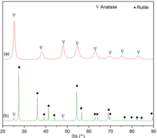
Figure 2 shows the X-ray diffractograms obtained from samples of TiO2 coated MWCNT, calcined at 500
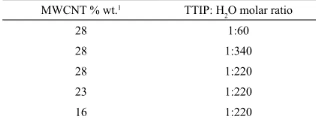
Table 1. Relative proportion of MWCNT, TTIP and H2O used to
produce TiO2-coated MWCNT.
MWCNT % wt.1 TTIP: H
2O molar ratio
28 1:60
28 1:340
28 1:220
23 1:220
16 1:220
1percent of MWCNT, related to the total weight of the MWCNT/
TiO2 hybrid
Figure 1. Raman Spectra in the range of: (a) 100-800 cm-1 from TiO2 coated MWCNT calcined at 500 and 1000ºC; (b) 1000-2000 cm-1 from pristine, functionalized MWCNT and TiO2 coated MWCNT
and 1000ºC. The formation of the TiO2 phase is confirmed,
having two different structures depending on the calcination temperature. At 500ºC the diffraction peaks correspond to the Anatase structure (JCPDS Nº 21-1272), as observed in Figure 2A. The sample calcined at 1000ºC exhibited peaks predominantly from the Rutile phase ( JCPDS Nº 21-1276), see Figure 2B, along with a small amount of Anatase indicated by the presence of its main diffraction peak (101) at 2θ = 25.28º. From the equation (1), the weight percent of the Anatase phase, WA, was estimated to be 4.9%.
(1)
In equation (1), IA denotes the intensity of strongest
Anatase reflection, (101; 2θ=25.28º.) and IR is the intensity
of strongest rutile reflection (110; 2θ=27.44º)39,40.
A rough approximation of the crystallite size of the samples was calculated by the well-known Scherrer's equation (2)41
based on the full width at half maximum (FWHM), denoted as B in the equation, where θ is the diffraction angle and λ is the X-ray wavelength corresponding to CuKα radiation.
(2)
The obtained crystallite sizes were 10±2 nm for the (101) Anatase peak, in the sample calcined 500ºC, and 27±3 nm for the rutile peak (110), in the sample calcined at 1000ºC. The Cu kα2 contribution was not removed before measuring
the FWHM. These results show that the Anatase to Rutile transformation is accompanied by grain growth, as expected 34.
The morphological aspect of the TiO2 coated MWCNT
was observed by FEG-SEM. The Figure 3 shows the morphology of the as supplied MWCNT. Although they are highly agglomerated, it is possible to note their high aspect ratio. It can also be observed in Figure 3(a) the presence of metallic nanoimpurities at the extremities of few nanotubes, corresponding to the remaining seeds from the MWCNT synthesis process. After acid functionalization, these
impurities are dissolved, as observed in Figure 3(b). It is also observed from Figure 3(b) that the individual nanotubes are clearly visible after acid functionalization, being easier to differentiate from one to another. It is expected that acid functionalization also dissolve eventual amorphous regions present in the MWCNT42,43.
Figure 2. XRD patterns of TiO2 coated MWCNT, synthetized
by the sol-gel process and calcined at (a) 500ºC and (b) 1000ºC.
.
/
W
I
I
1
1 265
100
AR A
=
+
.
cos
D
B
0 9
i
m
=
Figure 3. FEG-SEM images of (a) Pristine MWCNT and (b)
Functionalized MWCNT.
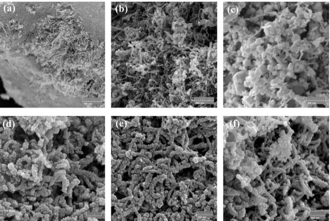
Samples of TiO2-coated MWCNT, obtained after the
sol-gel process using different titanium isopropoxide (TTIP) to H2O molar ratios, are shown in Figure 4. In Figure 4(a),
the molar ratio of 1:60 resulted in still entangled MWCNT, surrounded by agglomerates of the synthetized TiO2 particles.
This is a consequence of the low quantity of the water used to prepare the MWCNT suspension. The concentration of MWCNT in the suspension was very high (13.5 mg/ml), making difficult their fully dispersion. In the other extreme, decreasing the TTIP to H2O molar ratio to 1:340 significantly
improved the MWCNT dispersion, as observed in Figure 4(c). However, the volume of TiO2 particles formed is very
high. In this case, the concentration of MWCNT related to water was very low (1 mg/ml), promoting a quick growth of TiO2 nanoparticles since the hydrolysis process is very
fast and under this condition, the formation of isolated TiO2
nanoparticles in the solution is preferential over their growth as a layer over the MWCNT surface.
When the TTIP:H2O molar ratio was set at an intermediate
value of 1:220, it is apparent that a thin and very homogenous coating layer of TiO2 was formed over the MWCNT surface,
see the Figure 4(b). Very few isolated TiO2 nanoparticles
are formed. In this case, the MWCNT concentration in the suspension (8 mg/ml) results in an optimized balance between their dispersion and a moderate hydrolysis rate that is responsible for a controlled growth of the TiO2 coating
layer over the nanotubes surface.
As the best TTIP:H2O molar ratio was found to be 1:220
(see Figures 4(a) to 4(c)), the following step was to improve the homogeneity of the coating layer formed, by adjusting the MWCNT to TiO2 weight ratio. It can be observed from
Figures 4(d) to 4(f) that the MWCNT was successfully and homogenously coated by different thicknesses of TiO2. In
Figure 4. TiO2 coated MWCNT obtained using 28 %wt. of MWCNT and a TTIP:H2O molar ratio of: (a) 1:60, (b) 1:220, (c) 1:340.
Coatings obtained with a fixed molar ratio of 1:220 with different MWCNTs to TiO2 weight ratios: (d) 16% wt. and (e) 23% wt. In (f) a
higher magnification of (b) is shown, for comparison purpose.
in a thicker deposit layer. Furthermore, as the nanotubes are completely coated, few isolated TiO2 particles are also
formed. Increasing the proportion of MWCNT to 23 wt.% (see Figure 4(e)), it seems that the TTIP was totally consumed to form a thick layer of TiO2 over the nanotubes surface, and
no isolated TiO2 particles are formed. When the proportion of
MWCNT was increased to 28 wt.%, the TiO2 layer formed
is very thin, see Figures 4(b) and (f) .
In order to assess the thermal stability of the TiO2-coated
MWCNT in air, thermogravimetric analyses in oxidizing atmosphere were performed in samples coated using the best coating condition: 1:220 TTIP:H2O molar ratio and
a MWCNT proportion of 23%wt., calcined at 500 and 1000ºC. For comparison purpose, results from uncoated MWCNT are also presented, although this comparison is not straight. From the total mass of calcined samples, only 23% corresponds to the MWCNT, the rest correspond to TiO2. In the Figure 5(a), it is observed that the critical
temperature in terms of mass loss due to the oxidation of nanotubes is around 500 to 600ºC. This is easily observed from the derivative thermogravimetry curve (DTG) shown in the Figure 5 (b). In order to be sure that there was no carbon oxidation during calcination and that mass losses during TGA analysis of calcined samples were related to carbon oxidation and not to volatiles usually present after
sol-gel synthesis, some experiments involving calcination were repeated in the TGA equipment, under inert argon atmosphere. Such experiments simulated the calcination conditions, and a typical TGA curve obtained is shown as an insert in Figure 5(a). It can be observed from this figure that during calcination, about 10% of mass is lost, which can be related to volatiles. Consequently, it can be assumed that in calcined samples, the nanotubes are preserved. It can also be assumed that during the subsequent TGA analysis of calcined samples, under O2 atmosphere, the mass losses
are related exclusively to carbon oxidation.
Figure 5.. Thermogravimetric analysis (a) and DTG (b) of MWCNT
and TiO2-coated MWCNT, calcined at 500 and 1000°C. The inset in
(a) is TGA curve of MWCNT/TiO2 performed in argon up to 1000ºC
From the TGA analyzes of the TiO2-coated MWCNT
samples, it is possible to obtain the final mass of MWCNT and TiO2 separately. It can be done supposing that the mass
loss in O2 atmosphere correspond to the mass of exposed (uncoated) carbon nanotubes that are burned out, while the mass of the stable TiO2 remains unchanged. However,
Figure 5 (a) shows that for samples having the same weight of MWCNT (23%), the mass loss changes, depending on the calcination temperature. For samples calcined at 500ºC, the lost mass that can be related to carbon nanotubes was 19.7% from the initial 23.0%, while for samples calcined at 1000ºC, this loss was 15.7%. In other words, 85.6% of MWCNT present in samples calcined at 500ºC were lost during heating while in samples calcined at 1000ºC, this lost decreased to 68.3%. Table 2 resumes the potential of protection that the TiO2 layer confers to the MWCNT. Other
important effect observed from the DTG curves in Figure 5 (b) is that the thermal stability of the MWCNTs was improved as the calcination temperature increased. The oxidation peak of the sample calcined at 500ºC occurs at a temperature of 522ºC, while for the sample calcined at 1000ºC this peak temperature increases by 30ºC.
Assuming that most of the MWCNT are covered by a thin TiO2 layer, as observed in Figure 4 (e), and that during the
calcination in inert argon atmosphere no carbon loss occurs (as it can be seen in inset of Figure 5 (a)), the overall results show that the TiO2 layer shields the MWCNT protecting them
from high temperature oxidation, at least partially. The data presented in Table 2 enables to quantitatively compare the protection level of the TiO2 coating for different calcination
temperatures. It is possible to note that the protection level expressed by the ratio between initial weight and weight loss, increases from around 1.17 to 1.46, when comparing the sample calcined at 500ºC with the sample calcined at 1000ºC. Consequently, this protection is more effective in samples calcined at 1000ºC. As the TiO2 coating layer
structure changes from porous Anatase to Rutile, as the calcination temperature increases, this better protection can be attributed to the denser and more stable Rutile phase. A denser coating reduces the paths available for oxygen to penetrate and interact with the MWCNT surface, increasing the time for diffusion and conferring a better protection against thermal oxidation. These results create new possibilities to produce MWCNT reinforced MMC by conventional and well established processing routes, reducing the risk of nanotubes damages caused by their exposition to high temperature
cycles. Furthermore, the nanotubes dispersion and wettability in metal matrices can also be improved, enabling an overall improvement on the mechanical properties of the composites.
4. Conclusions
TiO2 coated MWCNT hybrid materials have been
successfully obtained by sol-gel technique, using titanium isopropoxide as a precursor. The best conditions were a molar ratio TTIP:H2O of 1:220 and a mass proportion of 23% of
MWCNT related to the total mass of TiO2-coated MWCNT.
The increase in the ID/IG ratio obtained from Raman Spectroscopy confirm that the previous functionalization step was successful, as it introduces surface functional groups on the MWCNT surface that are necessary to the anchoring of the TiO2 layer. X-Ray diffraction and Raman
Spectroscopy shows that the TiO2 layer crystallizes in the
Anatase phase when calcined at 500ºC, and in the Rutile phase when calcined at 1000ºC. A small amount of Anatase still remains after calcination at this higher temperature.
Thermogravimetric analysis confirms that the TiO2 coating
layer confers a protection to the MWCNT in terms of high temperature oxidation. This protection is more effective as the layer is in the form of a dense and more stable rutile phase, obtained after inert gas calcination at 1000ºC.
5. Acknowledgments
The authors are thankful to the Associated Laboratory for Sensors and Materials (LAS-INPE - Brazil), for the FEG-SEM images and Raman Spectroscopy analysis and to CNPq for the financial support (Process No. 443395/2014-4).
6. References
1. Robertson DH, Brenner DW, Mintmire JW. Energetics of nanoscale graphitic tubules. Phys Rev B. 1992;45(21):12592. 2. Yao N, Lordi V. Young's modulus of single-walled carbon
nanotubes. J Appl Phys. 1998;84(4):1939-43.
3. Demczyk BG, Wang YM, Cumings J, Hetman M, Han W, Zettl A, et al. Direct mechanical measurement of the tensile strength and elastic modulus of multiwalled carbon nanotubes. Mater Sci Eng A. 2002;334(1):173-8.
4. Gohardani O, Elola MC, Elizetxea C. Potential and prospective implementation of carbon nanotubes on next generation aircraft and space vehicles: A review of current and expected applications in aerospace sciences. Prog Aerosp Sci. 2014;70:42-68.
Table 2. Carbon content in TiO2-coated MWCNT composites.
Initial MWCNT %wt.1 Calcination Temp. (°C) TGA %wt. loss2. (%wt1/%wt2)
23 500 19.7 (1.17)
23 1000 15.7 (1.46)
Notes: 1 MWCNT estimated from mass balance of the precursors; 2 MWCNT lost during TGA analysis in O
5. Li CD, Wang XJ, Wu K, Liu WQ, Xiang SL, Ding C, et al. Distribution and integrity of carbon nanotubes in carbon nanotube/ magnesium composites. J Alloys Compd. 2014;612:330-6. 6. Bakshi SR, Singh V, Seal S, Agarwal A. Aluminum composite
reinforced with multiwalled carbon nanotubes from plasma spraying of spray dried powders. Surf Coatings Technol. 2009;203(10-11):1544-54.
7. Ci L, Ryu Z, Jin-Phillipp NY, Rühle M. Investigation of the interfacial reaction between multi-walled carbon nanotubes and aluminum. Acta Mater. 2006;54(20):5367-75.
8. Liao J, Tan M-J. Mixing of carbon nanotubes (CNTs) and aluminum powder for powder metallurgy use. Powder Technol. 2011;208(1):42-8.
9. Laha T, Kuchibhatla S, Seal S, Li W, Agarwal A. Interfacial phenomena in thermally sprayed multiwalled carbon nanotube reinforced aluminum nanocomposite. Acta Mater. 2007;55(3):1059-66.
10. Bakshi SR, Singh V, Balani K, McCartney DG, Seal S, Agarwal A. Carbon nanotube reinforced aluminum composite coating via cold spraying. Surf Coatings Technol. 2008;202(21):5162-9. 11. Travessa DN, Lieblich M. Dispersion of Carbon Nanotubes in
AA6061 Aluminium Alloy Powder by the High Energy Ball Milling Process. Mater Sci Forum. 2014;802:90-5.
12. Hosseini SA, Ranjbar K, Dehmolaei R, Amirani AR. Fabrication of Al5083 surface composites reinforced by CNTs and cerium oxide nano particles via friction stir processing. J Alloys Compd. 2015;622:725-33.
13. Kim WJ, Lee SH. High-temperature deformation behavior of carbon nanotube (CNT)-reinforced aluminum composites and prediction of their high-temperature strength. Compos Part A Appl Sci Manuf. 2014;67:308-15.
14. Kim HH, Babu JSS, Kang CG. Fabrication of A356 aluminum alloy matrix composite with CNTs/Al2O3 hybrid reinforcements. Mater Sci Eng A. 2013;573:92-9.
15. Li Q, Yan H, Ye Y, Zhang J, Liu Z. Defect location of individual single-walled carbon nanotubes with a thermal oxidation strategy. J Phys Chem B. 2002;106(43):11085-8.
16. Wu J, Zhang H, Zhang Y, Wang X. Mechanical and thermal properties of carbon nanotube/aluminum composites consolidated by spark plasma sintering. Mater & Des. 2012;41(0):344-8. 17. Kwon H, Estili M, Takagi K, Miyazaki T, Kawasaki A.
Combination of hot extrusion and spark plasma sintering for producing carbon nanotube reinforced aluminum matrix composites. Carbon N Y. 2009;47(3):570-7.
18. Liu ZY, Xiao BL, Wang WG, Ma ZY. Developing high-performance aluminum matrix composites with directionally aligned carbon nanotubes by combining friction stir processing and subsequent rolling. Carbon N Y. 2013;62:35-42.
19. Khorasani S, Heshmati-Manesh S, Abdizadeh H. Improvement of mechanical properties in aluminum/CNTs nanocomposites by addition of mechanically activated graphite. Compos Part A Appl Sci Manuf [Internet]. 2015;68:177-83. Available from: http://linkinghub.elsevier.com/retrieve/ pii/S1359835X14003212
20. Laha T, Agarwal A, McKechnie T, Seal S. Synthesis and characterization of plasma spray formed carbon nanotube reinforced aluminum composite. Mater Sci Eng A. 2004;381(1-2):249-58.
21. Kang K, Bae G, Kim B, Lee C. Thermally activated reactions of multi-walled carbon nanotubes reinforced aluminum matrix composite during the thermal spray consolidation. Mater Chem Phys [Internet]. 2012;133(1):495-9. Available from: http:// linkinghub.elsevier.com/retrieve/pii/S0254058412000958
22. Yan L, Tan Z, Ji G, Li Z, Fan G, Schryvers D, et al. A quantitative method to characterize the Al4C3-formed interfacial reaction: The case study of MWCNT/Al composites. Mater Charact. 2016;112:213-8.
23. Deng CF, Wang DZ, Zhang XX, Li AB. Processing and properties of carbon nanotubes reinforced aluminum composites. Mater Sci Eng A. 2007;444(1-2):138-45.
24. Park JK, Lucas JP. Moisture effect on SiCp/6061 Al MMC: Dissolution of interfacial Al4C3. Scr Mater. 1997;37(4):511-6. 25. Manivannan R, Daniel A, Srikanth I, Kumar A, Sarkar R, Ghoshal
P, et al. Thermal Stability of Zirconia-coated Multiwalled Carbon Nanotubes. Def Sci J. 2010;60(3):337-42.
26. Inam F, Vo T, Kumara S. Improving oxidation resistance of carbon nanotube nano- composites for aerospace applications. In: 2nd International Conference on Advanced Composite Materials and Technologies for Aerospace Applications. Wrexham, UK; 2012. p. 1-6.
27. Jo I, Cho S, Kim H, Jung BM, Lee S-K, Lee S-B. Titanium dioxide coated carbon nanofibers as a promising reinforcement in aluminum matrix composites fabricated by liquid pressing process. Scr Mater. 2016;112:87-91.
28. Gao B, Chen GZ, Li Puma G. Carbon nanotubes/titanium dioxide (CNTs/TiO2) nanocomposites prepared by conventional and novel surfactant wrapping sol-gel methods exhibiting enhanced photocatalytic activity. Appl Catal B Environ. 2009;89(3-4):503-9.
29. Gao B, Peng C, Chen G, Lipuma G. Photo-electro-catalysis enhancement on carbon nanotubes/titanium dioxide (CNTs/ TiO2) composite prepared by a novel surfactant wrapping sol-gel method. Appl Catal B Environ. 2008;85(1-2):17-23.
30. Yan J, Wu G, Guan N, Li L, Li Z, Cao X. Understanding the effect of surface/bulk defects on the photocatalytic activity of TiO2: anatase versus rutile. Phys Chem Chem Phys. 2013;15(26):10978-88.
31. Silva WM, Ribeiro H, Seara LM, Calado HDR, Ferlauto AS, Paniago RM, et al. Surface properties of oxidized and aminated multi-walled carbon nanotubes. J Braz Chem Soc. 2012;23(6):1078-86.
32. Yan X, Tay BK, Yang Y. Dispersing and functionalizing multiwalled carbon nanotubes in TiO2 sol. J Phys Chem B. 2006;110(51):25844-9.
34. Eder D, Windle AH. Morphology control of CNT-TiO2 hybrid materials and rutile nanotubes. J Mater Chem. 2008;18(17):2036-43.
35. Wu C-H, Kuo C-Y, Chen S-T. Synergistic effects between TiO 2 and carbon nanotubes (CNTs) in a TiO 2 /CNTs system under visible light irradiation. Environ Technol. 2013;34(17):2513-9. 36. Gui MM, Chai S-P, Xu B-Q, Mohamed AR. Visible-light-driven
MWCNT@TiO2 core-shell nanocomposites and the roles of MWCNTs on the surface chemistry, optical properties and reactivity in CO2 photoreduction. RSC Adv. 2014;4(46):24007.
37. Zhou W, Pan K, Qu Y, Sun F, Tian C, Ren Z, et al. Photodegradation of organic contamination in wastewaters by bonding TiO2/ single-walled carbon nanotube composites with enhanced photocatalytic activity. Chemosphere. 2010;81(5):555-61.
38. Hamid SBA, Tan TL, Lai CW, Samsudin EM. Multiwalled carbon nanotube/TiO2 nanocomposite as a highly active photocatalyst for photodegradation of Reactive Black 5 dye. Chinese J Catal. 2014;35(12):2014-9.
39. Spurr RA, Myers H. Quantitative Analysis of Anatase-Rutile Mixtures with an X-Ray Diffractometer. Anal Chem. 1957;29(5):760-2.
40. Mardare D, Tasca M, Delibas M, Rusu GI. On the structural properties and optical transmittance of TiO2 r.f. sputtered thin films. Appl Surf Sci. 2000;156(1):200-6.
41. Mali SS, Betty CA., Bhosale PN, Patil PS. Synthesis, Characterization of Hydrothermally Grown MWCNT-TiO2 Photoelectrodes and Their Visible Light Absorption Properties. ECS J Solid State Sci Technol. 2012;1(2):M15-23.
42. Stobinski L, Lesiak B, Kövér L, Tóth J, Biniak S, Trykowski G, et al. Multiwall carbon nanotubes purification and oxidation by nitric acid studied by the FTIR and electron spectroscopy methods. J Alloys Compd. 2010;501(1):77-84.