DOI: http://dx.doi.org/10.1590/1980-5373-MR-2017-1099 Materials Research. 2018; 21(suppl. 1): e20171099
Transient Unidirectional Solidification, Microstructure and Intermetallics in Sn-Ni Alloys
Clarissa Barros da Cruza, Rafael Kakitania, Marcella Gautê Cavalcante Xavierb, Bismarck Luiz Silvac ,
Amauri Garciaa, Noé Cheunga, José Eduardo Spinellib*
Received: December 16, 2017; Revised: February 23, 2018; Accepted: February 28, 2018
The present research work examines the microstructural arrangements formed during the transient
solidification of eutectic Sn-0.2wt.%Ni and hypereutectic Sn-0.5wt.%Ni alloys. Also, it examines their respective correlations with solidification thermal parameters: eutectic growth rate (VE) and eutectic cooling rate (ṪE); length scales of matrix and eutectic phases: microstructural spacings and the corresponding tensile properties: ductility and strength. Both alloys were directionally solidified upwards under unsteady-state regime, and characterized by optical and scanning electron microscopy. Concerning the hypereutectic Sn-0.5wt.%Ni, the increase in Ni content is shown to influence both thermal behavior and cellular spacing (λC). The NiSn4 intermetallics is present in the eutectic mixture of both alloys, whilst in the Sn-0.5wt.%Ni alloy the primary phase has been identified by SEM-EDS as the Ni3Sn4 intermetallics. A β-Sn morphological cellular/dendritic transition occurs in the 0.2wt.%Ni eutectic alloy for ṪE> 1.2K/s. Despite that, regular cells in the hypereutectic alloy (0.5wt.%Ni) turns into plate-like cells for ṪE> 1.4K/s. If considered a reference cellular spacing about 20μm (i.e., λc
-1/2=0.22), the samples associated with the Sn-0.5wt.%Ni alloy
are shown to be associated with higher tensile strengths, but much lower ductility as compared
with the corresponding results of the eutectic alloy.
Keywords: Lead-free alloys, Transient solidification, Microstructure, Intermetallics, Tensile properties, Wettability.
*e-mail: [email protected]
1. Introduction
Nickel (Ni) is one of the main alloying elements of Sn-based lead-free solder alloys. It has been largely added as third or as fourth element in Sn-Ag or Sn-Ag-Cu alloys, respectively. It is worth noting that the additions of minor alloying elements to Sn-based lead-free solders
has received a lot of attention recently in order to boost or
fine-tune various application properties1-6. For example,
Wang et al.7 found that Ni concentrations higher than 0.01 wt.% added to a Sn-2.5Ag-0.8Cu alloy may retard the growth of deleterious Cu3Sn particles layers at the alloy/copper interface even after an aging time of 2000 h. According to Nishikawa et al.8 the addition of 0.1 wt.% Ni to a Sn-3.5Ag alloy does not affect the joint mechanical strength with a Cu pad, but it changes the fracture mode.
The sustainable development of soldering processes
experiences a change towards lead-free electronic
products, the so called green electronics9,10. Consequently, manufacturers are required to set their furnaces and procedures for the application of lead-free solder alloys.
This is explained by the recent legal restrictions put in
place for lead-based solders. Sn-Ni alloys are considered
possible substitutes, even though there is a lack of studies devoted to their microstructures and application properties11,12.
Understanding the microstructure evolution in these alloys as well as establishing correlations between microstructural
features and solidification thermal parameters (i.e., cooling rate and solidification velocity) is fundamental for the pre-programming of final application properties of as-soldered joints. Determination of solidification conditions might yield either a specified β-Sn morphology and size or a required intermetallic particle in eutectic and hypereutectic Sn-Ni alloys.
Such lack of knowledge regarding Sn-Ni alloys is quite unexpected considering that Ni is a very common substrate in electronic packaging. Ni is largely employed since soft soldering applications involving Ni and Sn
represent slower growth kinetics as compared, for
example, with that occurring between Cu and Sn12. The existing research efforts dedicated to Sn-Ni solder alloys
put emphasis on examining and identifying the formed
intermetallics in compositions of interest. One of the few studies has shown that the NiSn4 intermetallics (IMC)
aDepartamento de Engenharia de Materiais e Manufatura, Universidade de Campinas - UNICAMP,
13083-860, Campinas, SP, Brasil
bDepartamento de Engenharia de Materiais, Universidade Federal de São Carlos - UFSCar,
13565-905, São Carlos, SP, Brasil
can be formed by either primary precipitation during solidification or eutectic transformation11-13. Overall,
the Sn-NiSn4 eutectic structure has been identified as
the predominant one regardless the tested solidification
conditions, which varied from 120K/s to 0.022K/s11. The
same research showed that for hypereutectic compositions
and solidification cooling rates in the range 1-10K/s, a very large fraction of primary Ni3Sn4 IMC grew to the detriment of the primary NiSn4 IMC.
Various studies devoting to develop alternative and
new solder alloys have been recently performed14-20.
The aim was to characterize microstructure features and
determine their correlations with solidification thermal
parameters, that is, the eutectic growth rate (VE) and the eutectic cooling rate (ṪE). This kind of knowledge ought to be expanded for Sn-Ni alloys. Within this approach,
the main priority is to compare the final microstructures and how they could be induced via solidification cooling
rate. In addition, in what manner the Ni content can
affect the microstructure features and properties such
as wettability and tensile properties. In general, the soundness of an alloy depends on the morphology/size of the β-Sn matrix and on the size/nature of phases
surrounding it21,22.
The microstructure features of directionally solidified
Sn-0.7Cu alloys containing minute additions of Ni were recently investigated. It has been reported that Ni modified alloys with 500 ppm and 1000 ppm of Ni developed both the (Cu,Ni)6Sn5 phase and the Ni3Sn4 primary IMC for specimens experiencing fast cooling
conditions23. Within this work, the mean equilibrium contact angles determined for the Sn-0.7Cu, Sn-0.7Cu-0.05Ni and Sn-0.7Cu-0.1wt%Ni alloys were 19.1°, 12.9° and 36.0° respectively. These values can be considered compatible to those reported for Sn-Pb alloys.
According to Kong et al.24, the increase in Sn content of Sn-Ni alloys can lead to better wettability, and such alloys are often required in practical applications mainly because of such essential quality.
In order to gain insight into microstructure formation and solidification thermal parameters of eutectic Sn-0.2wt.%Ni and hypereutectic Sn-0.5wt.%Ni solder alloys,
the present study aims to examine the experimental growth dependence of microstructure features on the
solidification cooling rate-Ṫ. Furthermore, the formation of intermetallics (either primary or eutectic) and the morphology and scale of the β-Sn phase will be discussed with basis on the cooling rate and alloy Ni content. The
cooling conditions provided in the present experiments are expected to permit the formation of some metastable
intermetallic phases. This way, the morphologies of stable and/or metastable eutectics will be assessed. Correlations
between tensile strength, ductility and representative
length scale of the microstructure are investigated.
2. Experimental Procedure
2.1. Directionally solidified castings
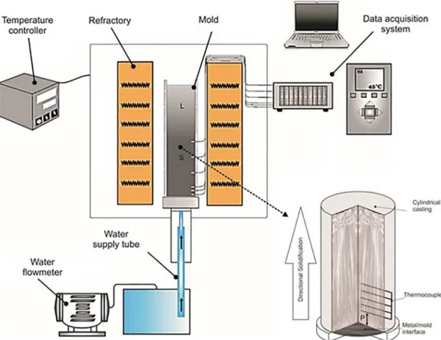
The eutectic 0.2 wt. %Ni and the hypereutectic Sn-0.5 wt. %Ni alloys have been assessed. Within this purpose, two directionally solidified (DS) Sn-Ni alloys castings were produced by using a water-cooled setup as shown in Fig. 125. The referred solidification system gives rise
to unsteady-state solidification conditions. The surface of the AISI 1020 low carbon steel bottom-part mold has been finished with a 1200 grit SiC abrasive paper. The following procedures were performed for each alloy: firstly, the alloy
is melted in situ by radial electrical wiring positioned
around a cylindrical stainless-steel container. Secondly, when the melt temperature is about 10% above either the eutectic (0.2Ni) or the liquidus (0.5Ni) temperatures, the
electric heaters are disconnected and at the same time the
water flow at the bottom of the container is started, which allows the onset of solidification. Finally, the evolution
of temperatures along the length of the castings was
monitored by fine type J thermocouples (0.2 mm diameter
wire), placed in the geometrical center of the cylindrical
mold cavity along its length. A detail of the thermocouples position can be seen in the bottom (right corner) of Fig. 1.
These cooling curves have been used to generate the values
of eutectic (ṪE) and tip (ṪL) cooling rates and of eutectic (VE) and tip (VL) growth rates for both alloys. The method allows plot the growth rates of various relative positions (P) along
the length of the casting5,6. It is based on tracking the passage
of the solidification front (liquidus or eutectic isotherms) by
each thermocouple in order to relate the thermocouple tracked
position (P) with the corresponding time (either tE or tL). Then, this procedure is replicated for various positions.
The eutectic and tip cooling rates were determined by considering the thermal data recorded immediately after the passage of the eutectic and liquidus fronts respectively by
each thermocouple. Both eutectic and liquidus fronts were
considered in the case of the hypereutectic Sn-0.5wt.%Ni
alloy while only the eutectic front was followed for the
eutectic Sn-0.2wt.%Ni alloy. The eutectic thermal parameters (ṪE and VE) for both alloys were those finally considered for comparison purposes. Consequently, the effects of the alloy Ni content on the solidification kinetics could be assessed.
There are various ways to define the cooling rate during a solidification process. One can either follow the slope
of the cooling curve at a certain temperature or divide the
solidification temperature interval (liquidus minus solidus) by the time required to complete solidification. In the
present manuscript we have experimentally determined both
variations in tip and eutectic cooling rates for both Sn-Ni alloys. This means that the slopes of the cooling curves
were determined taking as references the characteristic
3
Transient Unidirectional Solidification, Microstructure and Intermetallics in Sn-Ni Alloys
Figure 1. Vertical upward directional solidification casting assembly and connected devices used to produce the directionally solidified Sn-Ni alloys castings
2.2. Metallography, tensile and wetting tests
Metallographic analysis was performed to reveal the microstructural and morphological details of both Sn-Ni alloys castings, using grinding and polishing steps combined with the etchant: 95 mL of H2O, 2.5 mL of HNO3, 1.5 mL of HCl and 1.0 mL of HF.Micrographs were obtained using a light microscope with a coupled optical image processing system Olympus, BX41M-LED (Olympus Co., Japan) and using a Field Emission Gun (FEG) - Scanning Electron Microscope SEM-EDS FEI (Inspect S50L). The triangle method was employed to determine the cellular spacing (λc) on transverse sections of the DS castings 26,27.
Transverse specimens extracted from different positions along the length of the DS castings were prepared according to specifications of the ASTM Standard E 8M/04 and tested in an Instron 5500R machine at a strain rate of about 1 × 10⁻³ s-1.
The ultimate tensile strength and strain-to-failure have been determined and related to average microstructural spacings.
A goniometer Krüss DSHAT HTM Reetz GmbH model allowed the measurement of contact angles (θ) for each solder alloy/carbon steel substrate 22. The data of the tests were all acquired in triplicate.
3. Results and Discussions
3.1. Solidification thermal parameters
Temperatures recorded during solidification of the
Sn-Ni alloys allowed the plots in Fig. 2 to be generated. A
severe temperature reduction over time can be observed
for positions very close to the cooled bottom of the DS castings (i.e, black and red lines+symbols). This fast
cooling is explained because these positions are those
closer to the water-cooled surface of the mold, where heat extraction is very efficient. The moderate cooling associated with the subsequent positions higher than
~10mm is due to presence of both an already solidified layer and a gap formed between metal and mold caused
by volumetric shrinkage accompanying solidification. The cooling curves of Fig. 2 were used to generate plots of position (P), from the metal/mold interface, with the corresponding times (tE, tL) of the eutectic and
Figure 2. Thermal profiles generated through transient directional solidification of: (a) Sn-0.2wt.%Ni and (b) Sn-0.5wt.%Ni alloys DS
castings. TL is liquidus temperature and TE is eutectic temperature
as pointed out inside the graphs
Figure 3. Experimental plots of eutectic cooling rates and tip
cooling rates for: Sn-0.2 and 0.5 wt.%Ni alloys along the length of the directionally solidified castings
V=f(tE) and V=f(tL). By replacing t=f(P) with t inside the equation for V, resultant equations of the forms VE=f(P) and VL=f(P) have been obtained.
Figure 4. Experimental plots of eutectic growth rates and tip
growth rates for: Sn-0.2 and 0.5 wt.%Ni alloys along the length of the directionally solidified castings
3.2. Growth of regular, plate-like cells and
dendrites
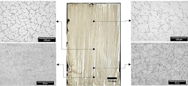
Vertically aligned columnar grains formed the macrostructures revealed for the DS 0.2wt.%Ni and Sn-0.5wt.%Ni alloys castings, as can be observed in the central images of Fig. 5 and Fig. 6. The grains follow the direction of growth, which is mainly parallel to the heat flow pathways as projected downwards. Large primary intermetallics can be observed in the microstructures of the Sn-0.5wt.%Ni alloy in Fig. 6. The equilibrium microstructures of hypereutectic Sn-Ni alloys consist of primary Ni3Sn4 crystals enveloped in a β-Sn+Ni3Sn4 eutectic mixture
11, while for the eutectic Sn-Ni alloy the equilibrium microstructure is formed by the β-Sn+Ni3Sn4 mixture. However, the growth of β-Sn
cells and intermetallic particles appears to prevail in all
Sn-Ni alloys samples, despite the presence of primary intermetallics for the Sn-0.5wt.%Ni alloy.
It appears that the large primary intermetallics that form
first are able to incorporate part of the nickel available in
the liquid immediately ahead of the solidification front. The experimental evolution of cooling rates (Ṫ) and
growth rates (V) along the length of both Sn-0.2 and 0.5wt.%Ni alloys castings are plotted in Fig. 3 and Fig. 4, respectively. These solidification thermal parameters were charted against the position P in the castings, so that the influence of the alloy Ni content could be noticed.
Within these graphs, the first noted feature is that both
tip cooling (ṪL) and growth (VL) rates profiles for the Sn-0.5wt.%Ni alloy casting are much higher than the eutectic referred values ṪE and VE. This difference is more substantial for positions (P) closer to the bottom of the casting.
The eutectic-related profiles in Fig. 3 and Fig. 4 (triangles and squares) depict higher cooling rates for the hypereutectic alloy whilst very close VE values can be observed when the Sn-0.2 and 0.5wt.%Ni alloys are compared. From P=10mm onwards both
alloys present very similar experimental evolutions
5 Transient Unidirectional Solidification, Microstructure and Intermetallics in Sn-Ni Alloys
Figure 5. Columnar grains macrostructure and selected transverse microstructures showing the β-Sn morphological evolution across the Sn-0.2wt.%Ni alloy casting
Figure 6. Columnar grains macrostructure and selected transverse microstructures showing the β-Sn morphological evolution from the bottom to top of the Sn-0.5wt.%Ni alloy casting
Hence, the liquid will become depleted of Ni until it reaches the eutectic composition. Then, one can consider the remaining liquid composition as eutectic (~0.2wt.%Ni) or close to that. It is very hard to distinguish between primary Sn growth and eutectic growth in Sn-Ni alloys under non-equilibrium conditions because the melting temperature of Sn is 231.96 °C, which is very close to the eutectic temperature of 231.15 °C 28. It is worth noting
that the displacement of the eutectic isotherm was that
considered in the present investigation to determine VE and ṪE, as shown in Fig. 3 and Fig. 4. Considering that
the present experiments are monitoring macroscopic heat flow conditions during solidification allied to
the proximity of the aforementioned transformation temperatures, the eutectic isotherm appears to be the
one, as is the case for the Sn-Ni alloys. Consequently,
the corresponding primary phase will be more highly undercooled and tend to grow faster than the eutectic29.
As can be seen in Fig. 5 for the Sn-0.2wt.%Ni
alloy, a reverse transition from dendrites to cells can be
observed for positions, P, higher than 50mm. Within this
occurrence, both cells and dendrites come into coexistence
for ṪE< 1.2 K/s. This is rather unusual since the regular
morphological transition is reported to evolve from cells to dendrites with the increase in cooling rate21,29, which is the opposite of what is observed here.
A recent study on rapid solidification of the Sn-0.7 wt.% Cu by impulse atomization30 stated a prevalence of high-cooling rates cells for high-cooling rates higher than 12.0 K/s,
which is around 10 times higher than the critical value found
for the Sn-0.2 wt.% Ni alloy in the present investigation. Moderate values of both growth rate (VL > 0.4 mm/s) and cooling rate (Ṫ> 1.2 K/s) characterized the critical values for the incidence of the so-called high-velocity cells for a Sn- 5.5 wt%Sb alloy. In this case, the critical value for cooling rate is the same as we found in the present study.
Another investigation with the Sn-0.2wt.%Ni alloy
against a copper cooled mold induced the occurrence of
high cooling rates cells for ṪE > 5.5K/s, followed by the growth of dendrites with the decrease in the cooling rate. The anticipated growth of dendrites links with cooling rates 4.5 times higher. This appears to be associated with the strong instabilities on the solid/liquid interface motivated by the dissolution of copper from the mold into the liquid. Indeed,
copper substrates exhibit higher ability to be dissolved by
Sn-based alloys than that offered by steels molds31. As can be seen in the top right corner of Fig. 6, farther away from the bottom surface of the Sn-0.5wt.%Ni alloy, the microstructure is consisted of side by side β-Sn plates. Despite the non-equilibrium solidification conditions, lower cooling rates (<1.4 K/s) seem to induce a plate-like cellular structure to be formed. This finding is in agreement with the reports in the literature. Xu et al.32
stated that the growth of cells might follow the path:
poxes, plate-like cells and regular cells.
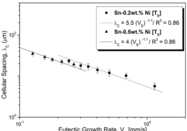
Fig. 7 and Fig. 8 show the experimental variations found for cellular spacing, λc, as a function of the eutectic cooling rate and the eutectic growth rate, respectively. Points are average
spacing values along with their standard deviations for each
position monitored in the DS castings. The exponent -0.55 characterizing the cooling rate-dependent power functions
is the same reported in other investigations with binary alloys6,12,15,17. When comparing the results for both Sn-Ni alloys, it is possible to infer that, for any considered cooling
rate, λc of the Sn-0.5wt.%Ni alloy will be higher than that of the Sn-0.2wt.%Ni alloy. However, if a certain growth rate, VE, is taken in account in Fig. 8 (that is: ~0.3mm/s), very similar microstructural spacings may characterize the length scales of the β-Sn phase related to the Sn-0.2 and 0.5 wt.%Ni alloys.
Figure 7. Experimental growth correlations expressing the variation
of cellular spacing with the eutectic cooling rate for the Sn-Ni alloys.
R2 is the coefficient of determination
Figure 8. Experimental evolution of cellular spacing with the
eutectic growth rate for the Sn-Ni alloys. R2 is the coefficient of
determination
3.3. Growth of intermetallics (IMC) during
transient solidification of Sn-Ni alloys
As previously shown in Fig. 5 and Fig. 6, the intermetallic particles form the boundaries of the β-Sn cells. The SEM-EDS results in Fig. 9 elucidate that the plate-like particles are the non-equilibrium NiSn4 IMC33,34. This diverges from the phase predicted by the equilibrium phase diagram, which is the Ni3Sn4 IMC
11. According to Belyakov and Gourlay11,13, NiSn
4 has growth advantages over equilibrium Ni3Sn4 due to easier interface attachment kinetics with β-Sn during the eutectic growth.
The prevalence of cells under relatively low cooling
7
Transient Unidirectional Solidification, Microstructure and Intermetallics in Sn-Ni Alloys
Canté and co-authors35 observed that the addition of
1.0wt.%Fe in the Al-1.0wt.%Ni alloy prevented the growth of dendrites. The ternary Al-1.0wt%Ni-1.0wt.%Fe alloy was characterized by an arrangement of cells while a dendritic array prevailed for the binary Al-1.0wt.%Ni alloy. It seems that iron (Fe) is able to assist the growth of cells, as observed in the case of the Sn-0.2wt.%Ni alloy (see Fig. 5), even for fairly low cooling rates.
Low fraction of primary intermetallics in hypereutectic compositions allowed single crystals to be extracted from
the matrix by selective etching of the β-Sn phase. The microstructures in the initial positions of the Sn-0.5wt.%Ni alloy casting (P=5mm and P=10mm) refer to tip cooling rates (ṪL) and tip growth rates (VL) higher than 16.0K/s and 2.0mm/s respectively. On the other hand, positions farther from the cooled bottom of the casting (P > 30mm) are associated with ṪL and VL lower than 3.5K/s and 0.6mm/s respectively.
As can be observed in Fig. 10, the hypereutectic samples contain many (up to three) morphologies of NiSn intermetallics coexisting in the same microstructure. Samples referring to ṪL > 16.0 K/s, as that shown in Fig. 10(a), are characterized by: elongated plate-like, tile-like particles (highlighted in blue); and particles of complex geometry outlined in red. As verified by the SEM-EDS results either the plate-like (right SEM image in Fig. 10(a)) or the tile-like (left SEM image) particles refer to the Ni3Sn4 phase. The number of facets in "tiles" is lower than that observed in the "plates". In addition, the "tiles" are shorter than the "plates".
The Ni3Sn4 IMC also grew for samples that experiencing slow cooling rates (ṪL < 3.5 K/s; Fig. 10(b)). Within this
nature, the fraction of primary particles was observed
to be lower than that characterizing the microstructures of the fast-cooled samples. Shorter sheet-like particles prevailed within these samples. This means that the
morphology of the Ni3Sn4 IMC changed from longer plates at 16 K/s to shorter sheets at 3.5 K/s.
In a recent study devoted to the formation of intermetallics in Sn-Ni alloys 11 it was found that both primary Ni
3Sn4 and primary NiSn4 might form for hypereutectic compositions.
According to this study, two factors appear to be decisive on which intermetallic will prevail: the cooling rate and the
alloy Ni content. In the present investigation, considering the levels of cooling rate and alloy Ni content, only primary particles growing as Ni3Sn4 have been identified.
3.4. Tensile properties and wettability of Sn-Ni
alloys
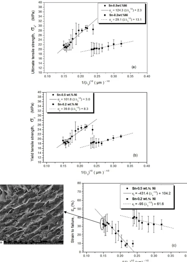
Fig. 11 plots the ultimate tensile strength (σu), yield tensile strength (σy) and strain to failure (δ) as a function of the microstructural spacings. Hall-Petch
type expressions were derived for both alloys and for the three tensile properties, so that a direct comparison is
possible. While the strength increases with the decrease in spacing, the ductility shows opposite trends.
The NiSn4 IMC having a plate-like morphology is considered better distributed between the cells for finer cellular arrangements. Consequently, this explains the improvement in the strength values with the increase in λc
-1/2, as observed
in Fig. 11(a) and Fig. 11(b). The rigid and interconnected finer eutectic arrangements, as can be seen in Fig. 9 and 10, may boost the strength of the Sn-0.2 and 0.5wt.%Ni alloys.
Due to the growth of hard intermetallics particles,
the Sn-0.5wt.%Ni alloy specimens resulted in higher σu and σy. However, much lower δ is attained as compared to the results found for the eutectic Sn-0.2wt.%Ni alloy.
Even though δ values are generally lower for the
hypereutectic alloy, some improvement appears to be
achievable for higher λc, i.e., for cellular regions in the alloy casting which were grown under slower cooling conditions.
The hypereutectic alloy microstructures in these regions
consist of Sn-rich plate-like together with regular cells surrounded by the β-Sn+NiSn4 eutectic structure as can be seen in the inserted SEM microstructure in Fig. 11(c). Higher ductility values were attained for such samples.
9
Transient Unidirectional Solidification, Microstructure and Intermetallics in Sn-Ni Alloys
Figure 11. Tensile properties and their correlations with the microstructural spacings for the Sn-0.2 and 0.5 wt.%Ni alloys: (a) Ultimate
tensile strength vs. (λc)
-1/2; (b) yield tensile strength vs. (λ
c)
-1/2 and (c) strain to failure vs. (λ
c)
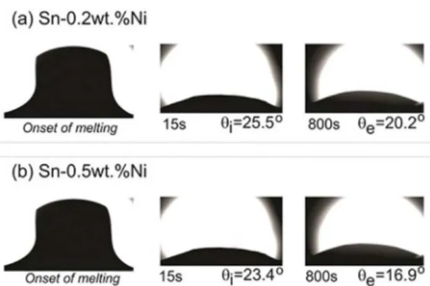
Two different periods of the experimental wetting scatter are considered during the progressing of contact angles for both examined alloys, which are initial instants
(first 45s) referred as initial angles θi; and ending part of the curves when an equilibrium regime is achieved (last 45s). This is related to the equilibrium contact angles, θe.
Fig. 12 shows these wetting angles for both Sn-0.2 and 0.5 wt.%Ni alloys. Values of both θi and θe determined for each alloy are shown in Fig. 12. It is worth noting that the Sn-0.5wt.%Ni alloy presented a slightly higher wettability than that observed for the eutectic alloy. This is because of the lower contact angles measured for the Sn-0.5wt.%Ni alloy.
• Experimental growth laws describing the evolution of cellular spacings with both the cooling rate and the growth rate have been proposed:
Sn-0.2wt.%Ni alloy: λc = 22 ṪE
-0.55 / λ
c = 5.5 VE
-1.1
Sn-0.5wt.%Ni alloy: λc = 35 ṪE
-0.55 / λ
c = 4 VE
-1.1
λc[µm]; Ṫ [°C/s] and VL[mm/s].
• Hall-Petch type correlations relating the ultimate tensile strength (σu), yield tensile strength (σy) and strain to failure (δ) as a function of the
microstructural spacings have been proposed:
Sn-0.2wt.%Ni alloy: σu = 29.1 (1/λc
1/2) +13.1 / σ
y = 39.8 (1/λc
1/2)
+8.3 / εf = -95 (1/λc
1/2) +61.6
Sn-0.5wt.%Ni alloy: σu = 124.3(1/λc
1/2) +2.3 / σ
y = 101.8 (1/λc
1/2)
+3.0 / εf = -431.4 (1/λc
1/2) +104.2
σ [MPa]; εf [%] and λc [µm]
• The Sn-0.5wt.%Ni alloy was shown to have a
slightly higher wettability than that observed
for the Sn-0.2wt.%Ni eutectic alloy, that is, initial contact angles θI of 23.4° and 25.5°, respectively.
5. Acknowledgements
The authors are grateful for the financial support
provided by FAPESP (São Paulo Research Foundation, Brazil: grants 2015/11863-5; 2016/18186-1; 2017/12741-6; 2017/15158-0), CNPq and the Postgraduate Program in Materials Science and Engineering (PPGCEM-UFRN).
6. References
1. El-Rehim AFA, Zahrana HY. Investigation of microstructure
and mechanical properties of Sn-xCu solder alloys. Journal of
Alloys and Compounds. 2017;695:3666-3367.
2. Yang L, Zhang Y, Dai J, Jing Y, Ge J, Zhang N. Microstructure, interfacial IMC and mechanical properties of Sn-0.7Cu-xAl
(x = 0-0.075) lead-free solder alloy. Materials & Design.
2015;67:209-216.
3. Belyakov SA, Xian JW, Sweatman K, Nishimura T, Akaiwa T, Gourlay CM. Influence of bismuth on the solidification of
Sn-0.7Cu-0.05Ni-xBi/Cu joints. Journal of Alloys and Compounds.
2017;701:321-334.
4. Böyük U, Marasli N. Dependency of eutectic spacings and
microhardness on the temperature gradient for directionally
solidified Sn-Ag-Cu lead-free solder. Materials Chemistry and
Physics. 2010;119(3):442-448.
5. Pereira PD, Spinelli JE, Garcia A. Combined effects of Ag content
and cooling rate on microstructure and mechanical behavior
of Sn-Ag-Cu solders. Materials & Design. 2013;45:377-383.
6. Osório WR, Leiva DR, Peixoto LC, Garcia LR, Garcia A. Mechanical properties of Sn-Ag lead-free solder alloys based
on the dendritic array and Ag3Sn morphology. Journal of Alloys
and Compounds. 2013;562:194-204. Figure 12. Advancing contact angles of the Sn-Ni droplets on AISI
1020 steel surface showing the initial, θi, and equilibrium angles, θe,
for the (a) Sn-0.2wt.%Ni and (b) Sn-0.5wt.%Ni alloys
Although very different amounts of Ni in the examined Sn-Ni alloys may result in variation of alloy properties, such as thermal diffusivity and latent heat of fusion, the lower θΙ
observed for the hypereutectic alloy may contribute to explain
the higher Ṫ seen in Fig. 3. Hence, the higher wettability of the Sn-0.5wt.%Ni alloy against the steel substrate may interfere in the evolution of solidification of the alloy, i.e., in ṪE.
4. Conclusions
• The macrostructures of the DS 0.2wt.%Ni and Sn-0.5wt.%Ni alloys castings were shown to be formed
by vertically aligned columnar grains parallel to the
heat flow pathways. A microstructure formed by β-Sn cells surrounded by the metastable β-Sn+NiSn4 eutectic mixture prevailed for both examined Sn-Ni alloys, despite the presence of the Ni3Sn4 primary intermetallics for the Sn-0.5wt.%Ni alloy.
• A reverse cellular/dendritic transition of the
eutectic morphology was shown to occur for
the Sn-0.2wt.%Ni alloy casting, in which high
cooling rate cells prevailed for cooling rates >
1.2 K/s. For the Sn-0.5wt.%Ni alloy casting it
was shown that a transition from regular cells
11
Transient Unidirectional Solidification, Microstructure and Intermetallics in Sn-Ni Alloys
7. Wang YW, Chang CC, Kao CR. Minimum effective Ni addition
to SnAgCu solders for retarding Cu3Sn growth. Journal of
Alloys and Compounds. 2009;478(1-2):L1-L4.
8. Nishikawa H, Komatsu A, Takemoto T. Effect of Ni or Co Addition to Sn-Ag Solder on Microstructure and Joint Strength
at Interface. Materials Transaction. 2008;49(7):1518-1523.
9. Ma H, Suhling JC. A review of mechanical properties of lead-free
solders for electronic packaging. Journal Materials Science.
2009;44(5):1141-1158.
10. Wu CML, Yu DQ, Law CMT, Wang L. Properties of lead-free
solder alloys with rare earth element additions. Materials
Science and Engineering: R: Reports. 2004;44(1):1-44. 11. Belyakov SA, Gourlay CM. NiSn4 formation during the
solidification of Sn-Ni alloys. Journal of Alloys and Compounds.
2012;25:48-59.
12. Xavier MGC, Cruz CB, Kakitani R, Silva BL, Garcia A, Cheung N, et al. Directional solidification of a Sn-0.2Ni solder alloy in water-cooled copper and steel molds:
Related effects on the matrix micromorphology, nature of
intermetallics and tensile properties. Journal of Alloys and
Compounds. 2017;723:1039-1052.
13. Belyakov SA, Gourlay CM. Role of Fe impurities in the
nucleation of metastable NiSn4. Intermetallics. 2013;37:32-41.
14. Silva BL, Garcia A, Spinelli JE. Complex eutectic growth and Bi precipitation in ternary Sn-Bi-Cu and Sn-Bi-Ag alloys. Journal of Alloys and Compounds. 2017;691:600-605. 15. Osório WR, Peixoto LC, Garcia LR, Mangelinck-Noël N,
Garcia A. Microstructure and mechanical properties of Sn-Bi,
Sn-Ag and Sn-Zn lead-free solder alloys. Journal of Alloys and
Compounds. 2013;572:97-106.
16. Gourlay CM, Nogita K, Read J, Dahle AK. Intermetallic
Formation and Fluidity in Sn-rich Sn-Cu-Ni Alloys. Journal
of Electronic Materials. 2010;39(1):56-69.
17. Spinelli JE, Rosa DM, Ferreira IL, Garcia A. Influence of melt convection on dendritic spacings of downward unsteady-state
directionally solidified Al-Cu alloys. Materials Science and
Engineering: A. 2004;383(2):271-282.
18. Donelan P. Modelling microstructural and mechanical properties
of ferritic ductile cast iron. Materials Science and Technology.
2000;16(3):261-269.
19. Moura ITL, Silva CLM, Cheung N, Goulart PR, Garcia A, Spinelli JE. Cellular to dendritic transition during transient
solidification of a eutectic Sn-0.7wt%Cu solder alloy. Materials
Chemistry and Physics. 2012;132(1):203-209.
20. Felberbaum M, Ventura T, Rappaz M, Dahle AK. Microstructure
formation in Sn-Cu-Ni solder alloys. JOM. 2011;63:52.
21. Rosa DM, Spinelli JE, Ferreira IL, Garcia A. Cellular growth during transient directional solidification of Pb-Sb alloys. Journal of Alloys and Compounds. 2006;422(1-2):227-238.
22. Reinhart G, Gandin CA, Mangelinck-Nöel N, Nguyen-Thi H, Spinelli JE, Baruchel J, et al. Influence of natural
convection during upward directional solidification:
A comparison between in situ X-ray radiography and
direct simulation of the grain structure. Acta Materialia.
2013;61(13):4765-4777.
23. Silva BL, Cheung N, Garcia A, Spinelli JE. Thermal Parameters, Microstructure, and Mechanical Properties of Directionally Solidified Sn-0.7 wt.%Cu Solder Alloys
Containing 0 ppm to 1000 ppm Ni. Journal of Electronic
Materials. 2013;42(1):179-191.
24. Kong Y, Shao J, Wang W, Liu Q, Chen Z. Electroless Sn-Ni alloy plating with high Sn content free of activation pretreatment. Journal of Alloys and Compounds. 2009;477(1-2):328-332. 25. Reyes RV, Bello TS, Kakitani R, Costa TA, Garcia A, Cheung
N, et al. Tensile properties and related microstructures aspects of hypereutectic Al-Si alloys directionally solidified under different melt superheats and transient heat flow conditions. Materials Science and Engineering: A. 2017;685:235-243.
26. Gündüz M, Çadirli E. Directional solidification of
aluminium-copper alloys. Materials Science and Engineering: A.
2002;327(2):167-185.
27. McCartney DG, Hunt JD. Measurements of cell and primary dendrite arms spacing in directionally solidified aluminium
alloys. Acta Metallurgica. 1981;29(11):1851-1863.
28. Okamoto H. Phase Diagrams of Dilute Binary Alloys. Materials
Park: ASM International; 2002.
29. Kurz W, Fisher DJ. Fundamentals of Solidification. Aedermannsdorf:
Trans Tech Publications; 1992. p. 85-87.
30. Moreno GR, Silva BL, Bogno AA, Henein H, Spinelli JE. Microstructure-property relations in as-atomized and as-extruded
Sn-Cu (-Ag) solder alloys. Journal of Alloys and Compounds.
2016;680:259-267.
31. Takemoto T, Takemoto M. Dissolution of stainless steels in molten lead-free solders. Soldering & Surface Mount Technology. 2006;18(3):24-30.
32. Xu W, Feng YP, Li Y, Li ZY. Cellular growth of Zn-rich Zn-Ag
alloys processed by rapid solidi?cation. Materials Science and
Engineering: A. 2004;373(1-2):139-145.
33. Schimpf C, Kalanke P, Shang SL, Liu ZK, Leineweber A.
Stacking disorder in metastable NiSn4. Materials & Design.
2016;109:324-333.
34. Wang CH, Kuo C, Chen H, Chen S. Effects of current density and temperature on Sn/Ni interfacial reactions under current
stressing. Intermetallics. 2011;19(1):75-80.
35. Canté MV, Brito C, Spinelli JE, Garcia A. Interrelation of
cell spacing, intermetallic compounds and hardness on a
directionally solidified Al-1.0Fe-1.0Ni alloy. Materials &