Synthesis, Characterization and Photocatalytic Performance of SnS Nanoibers and SnSe
Nanoibers Derived from the Electrospinning-made SnO
2Nanoibers
Li Chenga, Dan Lia, Xiangting Donga*, Qianli Maa, Wensheng Yua, Xinlu Wanga, Hui Yua, Jinxian
Wanga, Guixia Liua
Received: April 14, 2017; Revised: August 11, 2017; Accepted: September 04, 2017
SnO2 nanoibers were fabricated by calcination of the electrospun PVP/SnCl4 composite nanoibers. For the irst time, SnS nanoibers and SnSe nanoibers were successfully synthesized by double-crucible sulfurization and selenidation methods via inheriting the morphology of SnO
2 nanoibers used as precursors, respectively. X-ray difraction (XRD) analysis shows SnS nanoibers and SnSe nanoibers are respectively pure orthorhombic phase with space group of Pbnm and Cmcm. Scanning electron microscope (SEM) observation indicates that the diameters of SnS nanoibers and SnSe nanoibers are respectively 140.54±12.80 nm and 96.52±14.17 nm under the 95 % conidence level. The photocatalytic activities of samples were studied by using rhodamine B (Rh B) as degradation agent. When SnS or SnSe nanoibers are employed as the photocatalysts, the respective degradation rates of Rh B solution under the ultraviolet light irradiation after 200 min irradiation are 92.55 % and 92.86 %. The photocatalytic mechanism and formation process of SnS and SnSe nanoibers are also provided. More importantly, this preparation technique is of universal signiicance to prepare other metal chalcogenides nanoibers.
Keywords: Electrospinning, SnS, SnSe, Photocatalysis, Nanoibers
*e-mail: [email protected]
1. Introduction
In the past few decades, metal chalcogenides have attracted considerable research interest due to their outstanding semiconducting and optical properties and potential applications in future1. Among these materials, SnS and SnSe are increasingly important owing to their special semiconducting properties2. SnS is a p-type semiconductor with layered orthorhombic crystal structure. The orthorhombic herzenbergite modiication of SnS consists of double layers perpendicular to c axis in which Sn and S atoms are tightly bound. The direct and indirect band gap of SnS were reported to be 1.2-1.5 and 1.0-1.2 eV, respectively. The narrow band gap, non-toxic nature and the interesting structure of SnS make it a potential candidate for solar absorber in thin ilm solar cells and semiconductor sensors3. Tin selenide (SnSe), as a IV-VI compound semiconductor with a band gap of about 0.9 eV, can be widely used in infrared optoelectronic devices, holographic recording systems and memory switching devices4. Over the past several years, the synthesis of SnS and SnSe nanomaterials has been extensively explored, and considerable eforts have been made to control the size and shape of SnS and SnSe nanomaterials5,6.
Presently, many methods are employed to fabricate SnS and SnSe nanomaterials. Typical synthetic methods include chemical bath deposition7-9, thermal evaporation10,11,
electrodeposition12,13, spray pyrolysis technique14,15, sputtering16,
etc. Diferent morphological SnS and SnSe nanomaterials were prepared by using the above methods, including nanoparticles17,18, nanorods19, nanolakes20, nanoibers21, ilms2,22, nanoplate23, etc. By far, no reports on the preparation of SnS or SnSe nanoibers are found in literatures.
Conventionally, SnS or SnSe nanomaterials are prepared via calcination of a mixture of metal oxides or thiosulfates7,12, thiourea18 and sulfur powders or selenium powders at elevated temperatures. In this way, the as-prepared nanomaterials often have irregular morphology and can not inherit the peculiar morphologies of the metal oxides precursors because sulfur powders or selenium powders will melt and destroy the morphologies of the metal oxides. Hence, it is diicult to obtain metal chalcogenides nanoibers via direct solid-state reaction using metal oxides nanoibers as precursors. In order to solve this problem, a double-crucible method is proposed and used to retain the morphology of SnS or SnSe nanoibers using SnO2 nanoibers as precursors. Double-crucible technique has been proved to be an eicient, convenient and simple way to fabricate nanoibers, nanobelts and hollow nanoibers24. Meanwhile, electrospinning is a promising, straightforward and convenient way to prepare one-dimensional (1D) nanomaterials25-27 with diameters ranging from tens of nanometers up to micrometers owing to its easy control and low cost, including nanowires28, nanobelts29-31, core-shell structured nanoibers32-34, nanoibers35,36, nanosheets37-39
aKey Laboratory of Applied Chemistry and Nanotechnology at Universities of Jilin Province,
core-shell structured nanotubes40,41, etc. Nevertheless, the fabrication of SnS or SnSe nanoibers via electrospinning combined with a double-crucible technique is not reported. Hence, fabrication of SnS or SnSe nanoibers remains a challenging and meaningful subject of study.
In this work, PVP/SnCl4 composite nanoibers were fabricated by electrospinning, and SnO2 nanoibers were prepared through calcining the as-obtained composite nanoibers at 450 ºC. For the irst time, SnS or SnSe nanoibers were synthesized by a double-crucible technique we newly proposed via inheriting the morphology of SnO2 nanoibers. The samples were systematically characterized. The morphology, structure and photocatalytic properties of the resulting samples were investigated in detail, and the formation mechanisms of SnS and SnSe nanoibers were also presented.
2. Experimental Sections
2.1 Chemicals
Polyvinyl pyrrolidone (K90, Mr=90000, AR), N,N -dimethylformamide (DMF, AR), sulfur powders and selenium powders were purchased from Tianjin Bodi Chemical Co., Ltd. SnCl4·5H2O was bought from China Pharmaceutical Group Shanghai Chemical Reagent Company. Distilled water was homemade.
2.2 Preparation of PVP/SnCl
4composite
nanoibers via electrospinning
1.00 g of SnCl4·5H2O was dissolved in 7.60 g of DMF, and then 1.40 g of PVP was added into the above solution under magnetic stirring for 8 h to form homogeneous transparent spinning solution. In the spinning solution, the mass ratios of PVP, SnCl4 and DMF were equal to 14:10:76. Subsequently, the spinning solution was electrospun at room temperature using ordinary electrospinning setup under a positive high voltage of 13 kV, the distance between the capillary tip and the collector was ixed to 15 cm, and relative humidity was 20 %-30 %. With the evaporation of DMF, a dense web of PVP/SnCl4 composite nanoibers was formed on the collector.
2.3 Synthesis of SnO
2nanoibers
The above PVP/SnCl4 composite nanoibers were calcined at 450 °C for 3 h with a heating rate of 1 °C·min-1. Then the calcination temperature was decreased to 200 °C at a rate of 1 °C·min-1. Finally, samples were naturally cooled down
to room temperature and SnO2 nanoibers were obtained.
2.4 Fabrication of SnS nanoibers by a
double-crucible sulfurization method
2.00 g of sulfur powders were loaded into a small crucible, and then 3.00 g of carbon rods and 0.20 g of SnO2 nanoibers
were subsequently put into it. The small crucible was placed into a big crucible. Next, 2.00 g of sulfur powders were loaded into the space between the two crucibles, and then the big crucible was covered with its lid. We call this process a double-crucible method. Finally, the crucibles were heated to 800 °C with a heating rate of 5 °C·min-1 and remained for 4 h, then the temperature was decreased to 200 °C at a cooling rate of 2 °C·min-1, followed by natural cooling down to ambient temperature. In the sulfurization process, Ar gas is used as shielding gas. Thus, SnS nanoibers were acquired.
2.5 Preparation of SnSe nanoibers via a
double-crucible selenidation method
The procedure was the same as the sulfurization process, except that 5.00 g of selenium powders was used instead of sulfur powders and the selenidation reaction was conducted at 700 °C for 3 h.
2.6 Characterization methods
X-ray difraction (XRD) analysis was performed using a Rigaku D/max-RA X-ray difractometer with Cu kα radiation of 0.15418 nm. The size and morphology of the products were investigated by an XL-30 ield emission scanning electron microscope (SEM) made by FEI Company. The purity of the products was examined by OXFORD ISIS-300 energy dispersive X-ray spectrometer (EDS) attached to the SEM. The histograms of diameters distribution were drawn by Image-Pro-Plus 6.0 and origin 8.5 softwares. All the determinations were performed at room temperature.
2.7 Evaluation of photocatalytic performance
In a typical photocatalytic reaction, 5 mL of 0.1 g·L-1 Rh B solution was added into 95 mL of distilled water, then 0.05 g of the as-prepared SnS and SnSe nanoibers were dispersed into the above aqueous solution of Rh B and the solution was stirred for 2 h in the dark to reach adsorption-desorption equilibrium. Then the solution was directly exposed under the ultraviolet light (500 W ultraviolet lamp with main emission wavelength of 365 nm) at an irradiation distance 20 cm with stirring to trigger decomposition of the Rh B molecules. In a 20-minute interval, 4 mL solution was sampled and centrifuged to remove the photocatalyst samples. The concentration of Rh B solution was analyzed. The degradation rate of Rh B was estimated on the basis of the following formula:
where A0 was the absorbance of Rh B in the dark and
At was the absorbance of Rh B at given time intervals after irradiation, D was the degradation rate of the Rh B.
%
/
%
3. Results and Discussion
3.1 XRD analysis
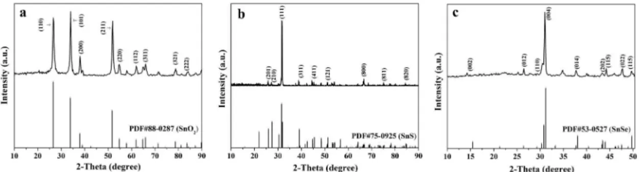
Figure 1a shows the XRD patterns of SnO2 nanoibers. All the difraction peaks are highly consistent with those of the pure tetragonal-phase of SnO2 (PDF#88-0287) with space group of P42/mnm. Obvious difraction peaks are located near 2θ=26.2° (110), 33.9° (101), 37.9° (200), 51.9° (211), 54.8° (220), 62.9° (112), 65.9° (311), 78.8° (321), 83.9° (222), etc. No difraction peaks of any other phases or impurities are also detected, indicating that pure-phase SnO2 nanoibers are successfully prepared.
Figure 1b reveals the XRD patterns of SnS nanoibers, and the difraction peaks can be easily indexed to those of the pure orthorhombic phase of SnS (PDF#75-0925), and the space group is Pbnm. Obvious difraction peaks are situated near 2θ=25.9° (201), 25.6° (210), 31.8° (111), 37.0° (311), 44.8° (411), 51.2° (121), 66.2° (800), 75.6° (811), 84.2° (820), etc. No peaks of any other phases or impurities are also detected, implying that crystalline SnS is acquired.
Figure 1c manifests shows the XRD patterns of SnSe nanoibers. Its relection peaks can be readily indexed to those of the pure orthorhombic phase of SnSe (PDF#53-0527), and the space group is Cmcm. Obvious difraction peaks are located near 2θ=15.5° (002), 26.5° (012), 28.5° (110), 31.0° (004), 38.0° (014), 43.2° (202), 44.2° (115), 47.6° (022), 49.6° (115), etc. No peaks of any other phases or impurities are detected, indicating that crystalline SnSe is obtained.
3.2 Morphology observation
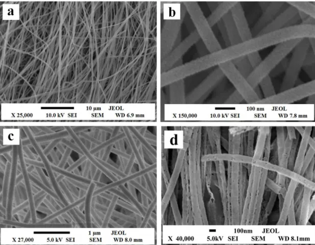
The morphologies of the products are characterized by scanning electron microscope (SEM). Figure 2 manifests the representative SEM images of PVP/SnCl4 composite nanoibers, SnO2 nanoibers, SnS nanoibers and SnSe nanoibers. From Figure 2a, it can be noticed that PVP/SnCl4 composite nanoibers have smooth surface and uniform diameter. After calcination at 450 °C, the diameter of SnO2
nanoibers greatly decreases due to loss of the PVP and associated organic components, as revealed in Figure 2b. SnS nanoibers and SnSe nanoibers have relatively rough surface, as seen in Figure 2c and 2d. From these analyses, we can safely conclude that the double-crucible technique we proposed here can remain the morphology of the SnO2 precursor nanoibers.
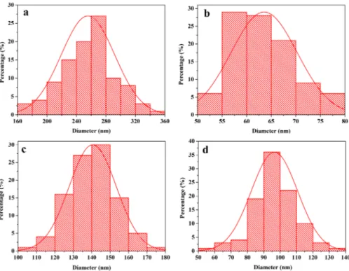
Histograms of diameters of these ibers are indicated in Figure 3. Under the 95 % conidence level, the diameters of ibers analyzed by Shapiro-Wilk method are normal distribution. The diameters of PVP/SnCl4 composite nanoibers,
SnO2 nanoibers, SnS nanoibers and SnSe nanoibers are 255.55±23.73 nm, 63.56±6.74 nm, 140.54±12.80 nm and 96.52±14.17 nm, respectively.
Figure 4 demonstrates the EDS spectra of PVP/SnCl4 composite nanoibers, SnO2 nanoibers, SnS nanoibers and SnSe nanoibers. EDS spectra analysis shows that C, N, O, Sn, Cl are the main elements in PVP/SnCl4 composite nanoibers and the presence of Sn, O corresponds to SnO2 nanoibers, as seen in Figure 4a and 4b. Sn, S are the main elements in SnS nanoibers and the presence of Sn, Se corresponds to SnSe nanoibers, as indicated in Figure 4c and 4d, C exists in SnS and SnSe nanoibers due to carbon rods loaded into the small crucible during the sulfurization and selenidation process, Pt comes from the conductive ilms coated on the samples for SEM analysis, and the O is owing to absorbed oxygen.
3.3 Photocatalytic properties
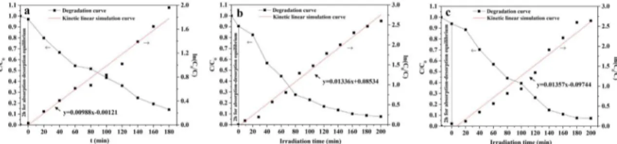
The photocatalytic activity of the SnO2 nanoibers, SnS nanoibers and SnSe nanoibers were evaluated by the degradation of Rh B solution under ultraviolet irradiation, as seen in Figure 5. Figure 5 displays the degradation curves of Rh B solution and irst-order reaction kinetics curves. The degradation rate of Rh B solution reaches 85.90 % using SnO2 nanoibers after 180 min irradiation. While SnS nanoibers or SnSe nanoibers are employed as the photocatalysts, the respective degradation rates of Rh B solution after 200 min
irradiation are 92.55 % and 92.86 %. Degradation of Rh B solution accords with the irst-order reaction kinetics equation:
where C0 is the initial concentration of Rh B solution, C is the concentration of Rh B solution at given time intervals after irradiation, K is the rate constant, t0 is the initial irradiation time and t is the irradiation time. The rate constant K of SnO2 nanoibers, SnS nanoibers and SnSe nanoibers are K1=0.00988 s
-1, K
2=0.01336 s -1 and K3=0.01357 s-1, respectively.
3.4 Possible mechanism of the
ultraviolet-induced photodegradation of Rh B
Based on the above results, a possible photocatalytic mechanism is indicated in Figure 6. As shown in Figure 6, SnS nanoibers and SnSe nanoibers with narrow band gap energy (ca. 1.01 eV and 0.90 eV) could be easily excited by ultraviolet light to generate photoelectrons and holes. Then the photo-generated electrons (e-) probably react with dissolved oxygen molecules to yield super oxide radical anions O2·
-, which on protonation forms the hydroperoxy HO2· and the
hydroxyl radical OH-. Simultaneously, the holes (h+) could oxidize OH- and H
2O to generate OH·. HO2· and OH· which are strong oxidizing agent could make C-C, C-O and C-H in Rh B molecule rupture to form harmless CO2 and H2O.
4. Formation Mechanisms for SnS
Nanoibers and SnSe Nanoibers
On the basis of above analytic of results, we propose the formation mechanisms for SnS nanoibers and SnSe nanoibers, as shown in Figure 7. PVP and SnCl4 were mixed with DMF to form spinning solution with certain viscosity. Then, PVP/SnCl4 composite nanoibers were obtained via electrospinning. During calcination process, PVP chain was broken and volatilized. With the increase in calcination temperature, Sn4+ was oxidized to form SnO
2 crystallites, many crystallites were combined into nanoparticles, then some nanoparticles were mutually connected to generate SnO2 nanoibers. PVP acted as template during the formation of SnO2 nanoibers. It was found from experiments that the average molecular weight and content of PVP in the spinning solution played important roles in the formation of SnO2 nanoibers. Next, SnO2 nanoibers were sulfurized and selenided using S and Se powders as sulfurizing and
ln
C
C
K t
t
0
=-
-
0T Y
Q
V
Figure 3. Histograms of diameters of PVP/SnCl4 composite nanoibers (a), SnO2 nanoibers (b), SnS nanoibers
(c) and SnSe nanoibers (d).
Figure 4. EDS spectra of PVP/SnCl4 composite nanoibers (a), SnO2 nanoibers (b), SnS nanoibers (c) and
Figure 5. Variation of degradation curves of Rh B with irradiation time over SnO2 nanoibers (a), SnS nanoibers (b) and SnSe nanoibers (c).
Figure 6. Possible mechanism of the ultraviolet-induced photodegradation of Rh B with SnS nanoibers and SnSe nanoibers.
Figure 7. Formation mechanisms of SnS nanoibers and SnSe nanoibers.
seleniding agents. In the process, S or Se reacted with SnO2 nanoibers to produce SnS nanoibers or SnSe nanoibers. During the process, S or Se powders and SnO2 nanoibers were separated by the carbon rods, which prevented SnO2 nanoibers from morphology damage. If SnO2 nanoibers directly mix with S or Se powders, melted S or Se will cut the SnO2 nanoibers into pieces, as a result, the morphology of SnO2 nanoibers cannot be retained. Carbon rods played an important role in the reduction via combination with O2 to produce CO, which reacted with oxygen species of SnO2 to give CO2 in the heating process. The double-crucible method we proposed here is actually a solid-gas reaction, which has
been proved to be an important method, not only can retain the morphology of SnO2 nanoibers, but also can fabricate SnS nanoibers and SnSe nanoibers with pure phase at relatively low temperature. Reaction schemes for formation of SnS nanoibers or SnSe nanoibers proceeded as follows:
(1)
(2)
(3)
(4)
5. Conclusions
In summary, SnO2 nanofibers were fabricated by calcination of PVP/SnCl4 composite nanoibers prepared via electrospinning, and pure-phase orthorhombic SnS nanoibers or SnSe nanoibers with space group of Pbnm or
/
PVP SnCl O C CO H O HCl SnO
4 2
450
2 2 2
o
+ + + +
C O CO
2 + 2 2
SnO S 2CO C SnS 2CO
2
800
2 o
+ + +
SnO Se 2CO C SnSe 2CO
2
700
2 o
Cmcm were obtained by sulfuration or selenization of the as-obtained SnO2 nanoibers. The as-prepared SnS nanoibers and SnSe nanoibers have relatively rough surface, their diameters are respectively 140.54±12.80 nm and 96.52±14.17 nm. SnS nanoibers and SnSe nanoibers possess excellent photocatalytic performance. The double-crucible technology we proposed here is of great importance, it can be applicable to synthesize other metal chalcogenides nanostructures with various morphologies.
6. Acknowledgments
This work was inancially supported by National Natural Science Foundation of China (51573023, 50972020), Natural Science Foundation of Jilin Province of China (20170101101JC), Industrial Technology Research and Development Project of Jilin Province Development and Reform Commission (2017C051), Science and Technology Research Planning Project of the Education Department of Jilin Province during the 13th Five-Year Plan Period (JJKH20170608KJ), Youth Foundation of Changchun University of Science and Technology (No. XQNJJ-2016-01).
7. References
1. Tang H, Yu JG, Zhao X. Solvothermal synthesis of novel dendrite-like SnS particles in a mixed solvent of ethylenediamine and dodecanethiol. Journal of Alloys and Compounds. 2008;460(1-2):513-518.
2. Park JP, Song MY, Jung WM, Lee WY, Lee JH, Kim HG, et al. Preparation of SnS Thin Films by MOCVD Method Using Single Source Precursor, Bis(3-mercapto-1-propanethiolato) Sn(II).
Bulletin of the Korean Chemical Society.
2012;33(10):3383-3386.
3. Zhang H, Hu C, Wang X, Xi Y, Li X. Synthesis and photosensitivity of SnS nanobelts. Journal of Alloys and Compounds. 2012;513:1-5.
4. Sharma J, Singh G, Thakur A, Saini GSS, Goyal N, Tripathi SK. Preparation and characterization of SnSe nanocrystalline thin ilms. Journal of Optoelectronics and Advanced Materials. 2005;7(4):2085-2094.
5. Hsu KC, Wu DY, Lin PY, Fu YS, Liao JD. Molecular assessment of histopathological staging in squamous-cell carcinoma of the head and neck. Journal of Applied Polymer Science. 2015;33:132-137.
6. Nassary MM. The electrical conduction mechanisms and thermoelectric power of SnSe single crystals. Turkish Journal
of Physics. 2009;33(4):201-208.
7. Gao C, Shen H. Inluence of the deposition parameters on the properties of orthorhombic SnS ilms by chemical bath deposition. Thin Solid Films. 2012;520(9):3523-3527. 8. Mukherjee A, Mitra P. Characterization of tin (II) sulphide thin
ilm synthesized by successive chemical solution deposition.
Indian Journal of Physics. 2015;89(10):1007-1012.
9. He HY, Fei J, Lu J. Rapid Chemical Bath Depositions and Properties of SnS Films. Materials and Manufacturing Processes. 2014;29(9):1044-1049.
10. Kawano Y, Chantana J, Minemoto T. Impact of growth temperature on the properties of SnS ilm prepared by thermal evaporation and its photovoltaic performance. Current Applied Physics. 2015;15(8):897-901.
11. Abdelrahman AE, Yunus WMM, Arof AK. Optical properties of tin sulphide (SnS) thin ilm estimated from transmission spectra.
Journal of Non-Crystalline Solids. 2012;358(12-13):1447-1451.
12. Mariappan R, Mahalingam T, Ponnuswamy V. Preparation and characterization of electrodeposited SnS thin ilms.
Optik - International Journal for Light and Electron Optics.
2011;122(24):2216-2219.
13. Steichen M, Djemour R, Gütay L, Guillot J, Siebentritt S, Dale PJ. Direct synthesis of single-phase p-type SnS by electrodeposition from a dicyanamide Ionic liquid at high temperature for thin ilm solar cells. Journal of Physical Chemistry C. 2013;117(9):4383-4393.
14. Reddy NK, Reddy KTR. Preparation and characterisation of sprayed tin sulphide ilms grown at diferent precursor concentrations.
Materials Chemistry and Physics. 2007;102(1):13-18.
15. Akbari T, Rozati SM. Preparation and growth of SnS thin ilm deposited by spray pyrolysis technique. Chemistry of Solid
Materials. 2014;2(1):33-39.
16. Chao J, Xie Z, Duan X, Dong Y, Wang Z, Xu J, et al. Visible-light-driven photocatalytic and photoelectrochemical properties of porous SnSx (x= 1,2) architectures. CrystEngComm. 2012;14(9):3163-3168.
17. Gou XL, Chen J, Shen PW. Synthesis, characterization and application of SnSx (x = 1, 2) nanoparticles. Materials Chemistry
and Physics. 2005;93(2-3):557-566.
18. Muthuvinayagam A, Viswanathan B. Hydrothermal synthesis and LPG sensing ability of SnS nanomaterial. Indian Journal
of Chemistry. 2015;54A:155-160.
19. An C, Tang K, Jin Y, Liu Q, Chen X, Qian Y. Shape-selected synthesis of nanocrystalline SnS in diferent alkaline media.
Journal of Crystal Growth. 2003;252(4):581-586.
20. Du M, Yin X, Gong H. Efects of triethanolamine on the morphology and phase of chemically deposited tin sulide.
Materials Letters. 2015;152:40-44.
21. Shen Z, Hu Y, Chen Y. Tin nanoparticle-loaded porous carbon nanoiber composite anodes for high current lithium-ion batteries.
Journal of Power Sources. 2015;278:660-667.
22. Sun YF, Cheng H, Gao S, Sun ZH, Liu QH, Liu Q, et al. Freestanding Tin Disulide Single-Layers Realizing Eicient Visible-Light Water Splitting. Angewandte Chemie. 2012;51(35):8727-8731. 23. Rath T, Gury L, Sánchez-Molina I, Martínez L, Haque SA.
Formation of porous SnS nanoplate networks from solution and their application in hybrid solar cells. Chemical Communications. 2015;51(50):10198-10201.
24. Kong Q, Wang J, Dong X, Yu W, Liu G. Synthesis and luminescence properties of LaOCl:Eu3+ nanostructures via the combination of electrospinning with chlorination technique. Journal of Materials
25. Hou Z, Li G, Lian HZ, Lin J. One-dimensional luminescent materials derived from the electrospinning process: preparation, characteristics and application. Journal of Materials Chemistry. 2012;22(12):5254-5276.
26. Tian J, Ma Q, Dong X, Yang M, Yang Y, Wang J, et al. Flexible composite nanobelts: facile electrospinning construction, structure and color-tunable photoluminescence. Journal of Materials
Science: Materials in Electronics. 2015;26(11):8413-8420.
27. Hou Z, Li C, Yang J, Lian H, Yang P, Chai R, et al. One-dimensional CaWO4 and CaWO4:Tb
3+ nanowires and nanotubes: electrospinning preparation and luminescent properties. Journal
of Materials Chemistry. 2009;19(18):2737-2746.
28. Ma Q, Wang J, Dong X, Yu W, Liu G. Flexible ribbon-shaped coaxial electrical Conductive nanocable array endowed with magnetism and photoluminescence. RSC Advances. 2015;5(4):2523-2530.
29. Han C, Ma Q, Dong X, Yu W, Wang J, Liu G. In situ synthesis of porous Fe3O4/C composite nanobelts with tunable magnetism,
electrical conduction and highly efficient. adsorption characteristics. Journal of Materials Science: Materials in
Electronics. 2015;26(4):2457-2465.
30. Liu Y, Wang JX, Dong XT, Liu GX. Fabrication of Gd3Ga5O12:Eu
3+ Porous Luminescent Nanobelts via Electrospinning. Chemical
Journal of Chinese Universities. 2010;31(7):1291-1296.
31. Xue H, Sun X, Bi J, Wang T, Han J, Ma Q, et al. Facile electrospinning construction and characteristics of coaxial nanobelts with simultaneously tunable magnetism and color-tuned photoluminescence bifunctionality. Journal of Materials
Science: Materials in Electronics. 2015;26(1):8774-8783.
32. Hou Z, Li C, Ma P, Cheng Z, Li X, Zhang X, et al. Up-Conversion Luminescent and Porous NaYF4:Yb
3+, Er3+@SiO
2
Nanocomposite Fibers for Anti-Cancer Drug Delivery and Cell Imaging. Advanced Functional Materials. 2012;22(13):2713-2722.
33. Ma Q, Wang J, Dong X, Yu W, Liu G, Xu J. Electrospinning preparation and properties of magnetic-photoluminescent
bifunctional coaxial nanoibers. Journal of Materials Chemistry. 2012;22(29):14438-14442.
34. Liu Z, Sun DD, Guo P, Leckie JO. An eicient bicomponent
TiO2/SnO2 nanoiber photocatalyst fabricated by electrospinning
with a side-by-side dual spinneret method. Nano Letters.
2007;7(4):1081-1085.
35. Yang F, Ma Q, Dong X, Yu W, Wang J, Liu G. A novel scheme to obtain tunable luorescent colors based on electrospun composite nanoibers. Journal of Materials Science: Materials
in Electronics. 2015;26(1):336-344.
36. Zhou X, Ma Q, Dong X, Wang J, Yu W, Liu G. Dy3+ and Eu3+ complexes co-doped lexible composite nanoibers to achieve tunable luorescent color. Journal of Materials Science: Materials
in Electronics. 2015;26(5):3112-3118.
37. Wang K, Shao C, Li X, Zhang X, Lu N, Miao F, et al. Hierarchical heterostructures of p-type BiOCl nanosheets on electrospun n-type TiO2 nanoibers with enhanced photocatalytic activity.
Catalysis Communications. 2015;67:6-10.
38. Wang K, Shao C, Li X, Miao F, Lu N, Liu Y. Heterojunctions of p-BiOI Nanosheets/n-TiO2 Nanoibers: Preparation and
Enhanced Visible-Light Photocatalytic Activity. Materials
(Basel). 2016;9(2):90.
39. Zhang Z, Shao C, Li X, Sun Y, Zhang M, Mu J, et al. Hierarchical assembly of ultrathin hexagonal SnS2 nanosheets onto
electrospun TiO2 nanoibers: enhanced photocatalytic activity
based on photoinduced interfacial charge transfer. Nanoscale.
2013;5(2):606-618.
40. Zhang P, Wang L, Zhang X, Shao CL, Hu J, Shao G. SnO2-core
carbon-shell composite nanotubes with enhanced photocurrent and photocatalytic performance. Applied Catalysis B: Environmental. 2015;166-167:193-201.