A Framework for Fault Tolerant Real Time Systems Based on Reconfigurable
FPGAs
Manuel G. Gericota, Luís F. Lemos, Gustavo
R. Alves
Department of Electrical Engineering – ISEP
Rua Dr. António Bernardino de Almeida
4200-072 Porto, Portugal
{mgg,lfl,gca}@isep.ipp.pt
Mário M. Barbosa, José M. Ferreira
Department of Electrical and Computer
Engineering – FEUP
Rua Dr. Roberto Frias
4200-465 Porto, Portugal
[email protected]
Abstract
♦To increase the amount of logic available to the users in SRAM-based FPGAs, manufacturers are using nanometric technologies to boost logic density and reduce costs, making its use more attractive. However, these technological improvements also make FPGAs particularly vulnerable to configuration memory bit-flips caused by power fluctuations, strong electromagnetic fields and radiation. This issue is particularly sensitive because of the increasing amount of configuration memory cells needed to define their functionality.
A short survey of the most recent publications is presented to support the options assumed during the definition of a framework for implementing circuits immune to bit-flips induction mechanisms in memory cells, based on a customized redundant infrastructure and on a detection-and-fix controller.
1. Introduction
The introduction of Very Large Scale Integration (VLSI) technologies increased substantially the reliability of electronic systems, when compared with the previous use of discrete components. Hence, the use of fault tolerance techniques was confined only to specific applications requiring high levels of reliability or operating on harsh environments. Shrinking transistors’ size leads to a greater integration and to a per unit power reduction, enabling chips to grow both in size and complexity. But new nanometer scales also brought negative aspects, such as a high probability of occurrence of memory bit-flips, caused by power fluctuations, electromagnetic interferences or radiation. This issue has a particular impact on the reliability of SRAM-based Field Programmable Gate Arrays (FPGAs). The exponential growth in the number of
♦ This work is supported by an FCT program under contract POSC/EEA-ESE/55680/2004
memory cells needed for configuration purposes makes them especially vulnerable to memory bit-flips, resulting on Single Event Upsets (SEU) and Multi-Bit Upsets (MBU) [1-7]. Despite faults due to memory bit-flips do not physically damage the chip, their effects are permanent, since the functionality of the circuits mapped into the device is permanently altered.
Although anti-fuse technology-based FPGAs are less prone to SEUs due to the absence of configuration memory cells, SRAM-based FPGAs have been the preferred choice, for instance, in space missions, like MARS 2003 Lander and Rover vehicles, where they were exposed to extremely harsh conditions. That’s because their processing performance is 10 to 100 times higher than the performance attained by anti-fuse technology-based FPGAs, and also due to their reconfigurable features, which enable resource multiplexing, updating of algorithms during long space missions, avoiding mission obsolescence, and correction of design flaws in orbit [8].
In non-reconfigurable technologies, such as ASICs, protection against SEUs is restricted to flip-flops, because logic paths between them are typically hard--wired. Notwithstanding, Single Event Transients (SETs), a charge transient induced in a wire by the incidence of an heavy ion, may be propagated to flip--flop inputs, where they have a high probability to be registered causing soft-errors in the user data. Besides, if it strikes a clock line, double-clocking may occur leading to an extemporaneous update that may affect, depending on the charge value and on line attenuation, part of or all the flip-flops driven by that line. Further protection is only achieved through full module redundancy. This is also a preferred choice to improve the reliability of highly critical real-time applications based on FPGAs [4, 8-10]. Due to their inherent configurability, FPGAs are especially suitable for the implementation of modular redundancy, since it does not require any new architectural feature and it is function independent. However, their dependency on memory cells to define logic paths makes these also susceptible to SEUs. Again,
in this case, the only effective protection is full module redundancy [9].
In a discrete implementation of a Triple Modular Redundancy (TMR) system, if a defect affects the functionality of one module, the reliability index of the system decreases, but the system still works correctly. In this method, extra components are used to instantaneously mask the effect of a faulty component, meaning that no propagation of the fault will occur. However, a second failure in one of the remaining modules may lead to a system failure. Ideally, when a module fails, it should be replaced to restore the initial system redundancy index, but this action may not be possible immediately. In certain cases, like in space applications, it may even be impossible. With FPGAs this drawback may be overcome without a significant rise in costs, because, in the event of a module failure, the initial system redundancy index may be restored just by performing a reconfiguration of the affected module. No physical replacement is therefore necessary.
The aim of this paper is to define a set of rules for a new framework for implementing highly critical real--time integrated systems based on dynamically reconfigurable FPGAs. The aim is to make these systems immune to faults emerging from memory bit-flips, by confining, detecting, locating and mitigating them. The proposed framework is built around a customised Triple Modular Redundancy implementation associated to a fault detection-and-fix controller. This controller is responsible for:
(i) detecting data incoherencies;
(ii) locating the faulty redundant module; and
(iii) restoring the original module configuration, fixing it without affecting the normal operation of the functional logic.
This mechanism was implemented in a XC2V1500, part of the Virtex-II FPGA family from Xilinx. This approach enables the confinement and detection of faulty modules, and the determination of when reconfiguration must be applied to restore proper system operation before cumulative errors, induced over time, leads to its failure. A short survey of the most recent data published concerning the impact of radiation induced faults on FPGAs and on FPGA based TMR implementations is reviewed to support the options assumed during the implementation phase. A discussion on the issues that come up during this phase, mainly concerning design options and architectural features of the FPGA, which may prevent an efficient implementation of the proposed framework, are presented. This work is part of a broader project, aiming the design of FPGA-based self repairing circuits. Several aspects related to its practical implementation are also pointed out, and current and future research lines are presented in the concluding section.
2. Background
The results of several radiation campaigns performed to understand the effects radiation induced faults have on the behavior of circuits implemented in SRAM-based FPGAs were reported in the literature by several authors [2, 3, 10]. These authors observed that, in general, radiation leads to changes on the correct functionality of the circuits, an effect defined as a Single Event Functional Interrupt (SEFI). A classification of SEFIs according to the affected resources and their effects was proposed in [1-2].
Several fault injection approaches, alternative to the always expensive radiation campaigns, may also be found in literature. A comparatively cheaper alternative is the use of electromagnetic interferences to conduct contactless fault injection. These are common disturbances in automotive vehicles, trains, airplanes, or industrial plants. Such a technique is widely used to stress digital equipment. Thanks to the use of commercial burst generators, this technique is easy to implement [7].
A different approach is the use of emulation techniques. Bit-flips are injected by direct manipulation of the configuration memory bitstream of the FPGA, either through changes in the original configuration bitstream or at run-time through dynamic reconfiguration [11, 12]. The greatest advantage of emulation methods is the higher controllability of the experiments, in contrast to the unpredictability of radiation or electromagnetic interference fault injection, which enables a better diagnostic of the effects of each SEU. A combination of both techniques, not only to increase the controllability of the experiments, but also to verify the accuracy of the emulation fault injection techniques used, may be found in [4, 7, 8, 13, 14].
Lately, several hardening techniques have been proposed to avoid SEU effects on the functional behavior of circuits. Correcting techniques based on dynamic reconfiguration, known as scrubbing, like those presented on [15-17], periodically read back the configuration memory to detect bit-flips caused by SEUs. If a bit-flip is detected the affected frame is reconfigured and the system reset thereafter. However, the same authors recognized some limitations to these techniques: a fault-free read back of the configuration bitstream does not always guarantee that a SEU did not occur. As an example, SEUs or SETs affecting flip-flop states occur without upsetting the bitstream but may severely disturb or halt function operation. Another drawback is fault detection latency. Reading back the whole configuration memory may take several to hundred of milliseconds, depending on the FPGA size and on the interface used to perform the read back operation. By then, the fault may already have caused the irreversible malfunctioning of the whole system,
eventually interrupting its operation. In some cases, it may even be impossible to recover from this situation.
Alternative techniques based on hardware redundancy were proposed without the aim of identifying and correcting the fault but just to mask its existence. Through TMR extensive testing, several authors have shown that SEU induced failures can be properly controlled for the Virtex family of FPGA devices [9, 10, 14, 18]. Fault tolerance is achieved using extra components to instantaneously mask the effect of a faulty component, meaning that no fault propagation will occur. Still, as no fault detection occurs, the faulty module is not replaced and therefore initial redundancy (and reliability) is not restored. Consequently, over time, cumulative faults will inevitably lead to a system failure.
The consideration of the results reached during radiation campaigns concerning MBUs due to single charged particles is also important, since they may potentially affect multiple redundant modules and produce incorrect values. The effects produced by MBUs are intrinsically related to the architecture of the configuration memory. In Virtex families, configuration memory is divided into one bit wide vertical frames that span from the top to the bottom of the array. Each column of Configurable Logic Blocks (CLBs) comprises multiple frames, which combine internal CLB configuration and state information with column routing and interconnection information. In [8] it is reported that, in the case of the Virtex family, MBUs occurred all in the same configuration frame while in the Virtex-II family the percentage of MBUs that occurred in the same configuration frame decreases to 88%. However, no MBUs spanned the configuration data of separated resource columns [4]. No correlation was observed between MBUs and module granularity sizes, which indicates that even at very fine granularities if the modules are placed far enough to not share routing networks, TMR is still a good option. These results also reveal some important information about the placement of the configurable memory cells inside the FPGA. This information is important to understand the fault induction mechanism due to radiation and electromagnetic interferences.
In sum, the association between dynamic reconfiguration and TMR seems thus far to be the most effective way to mitigate the effects of radiation and electromagnetic interferences, albeit some care must be taken during the mapping of the circuits into the FPGA.
The above reviewed experimental results and conclusions were taken into account when creating the framework for the design and implementation of radiation immune FPGA-based real-time systems that is proposed in this paper.
3. Framework bases
At this point, it is logical to infer, based on the previous analysis, that to protect the operation of an FPGA-based systems against radiation and electromagnetic interferences it has to be implemented using TMR. Moreover, it has to incorporate an autonomous mitigation mechanism to avoid system failures due to the cumulative effects of SEUs.
In a classic TMR implementation [19], the correct system output values are settled by voting elements that accept the outputs from three redundant sources and deliver the majority vote at their outputs. Each redundant source may be a simple gate or a more complex unit, like a microprocessor. The voting element accepts the outputs from the three sources and delivers the majority vote at its output. This concept can be extended to any number of redundant modules to produce an N-modular redundant (NMR) system, which can tolerate up to n module failures, where n=floor[(N-1)/2].
The reliability equation for an NMR system is given by [19]:
This assumes that the majority voter does not fail, which is an unrealistic principle. When this assumption is not verified, the reliability of the voter element will determine the reliability of the circuit, since it will fail if the voter fails, regardless of whether or not other modules fail. The reliability of a voter in a redundant system can be improved by replicating this element as well, in a scheme that is called T-TMR. For its proper nature, T-TMR implementations mask any single fault emerging during circuit operation. Multiple faults may also be masked providing that they affect only one of the redundant modules or voters, or, if upsetting different modules, they affect different signals and that bitwise comparison is used. In these cases, faults are confined to the module or voter where they emerged, not becoming visible outside.
To fully prevent functional problems caused by configuration upsets, each signal should enter the FPGA in triplicate, using three input pins. Otherwise, if a single input was connected to all three redundant modules, then a failure at the single input would cause the error to propagate through all the redundant modules, and thus the error would not be masked.
This same principle applies to clock signals. Each of the triplicate circuit modules should receive its own clock. Otherwise, spurious signals induced by SETs on a single clock line may lead to an extemporaneous update of all the three-module registers and to the asynchronous output of possibly incorrect values.
(
)
(N i) M i M n i NMRR
R
i
N
R
− =⋅
−
⋅
⎟⎟
⎠
⎞
⎜⎜
⎝
⎛
=
∑
1
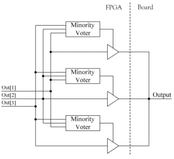
0Output signals should also leave the FPGA in triplicate, with minority voters monitoring each one of the outputs. The three signals converge to a same node outside. When one of the outputs is different from the others, the correspondent pin is driven to high impedance. Figure 1 illustrates this scheme.
Figure 1. Full TMR output scheme implementation.
To avoid the effect of MBUs on the different modules [4], the three redundant functional modules should be placed in different columns of the FPGA. Therefore, the FPGA should be divided in four vertical areas: three for the functional circuit modules and a fourth for the placement of the detection-and-fix controller. To avoid possible route networking shares, module’ interconnections to inputs and outputs should not cross different implementation areas. The overall implementation scheme is presented in figure 2, where ‘M’ stands for “Majority voters” while ‘m’ stands for “minority voters”.
When one or more faults appear in one of the modules or voters, the T-TMR implementation confines the fault and masks its existence, avoiding its propagation to the rest of the circuit. However, the cumulative effects of several faults induced over time may suppress the effectiveness of the confinement and masking mechanism, resulting in fault propagation. With the aim of detecting the emergence of faults a detection--and-fix controller is implemented in the fourth area defined on the FPGA logic space. A detailed overview of the detection-and-fix controller structure is shown in figure 3. This controller is responsible for detecting data incoherencies, locating the faulty module and restoring the original configuration. This is done transparently, through partial reconfiguration of the affected functional module, without human intervention, since physical
component replacement is not needed. As a result, a higher level of maintainability is achieved without implying the inoperability of the circuit.
m M m M m M Implementation area for module
3
Inputs Outputs
Implementation area for module
1
Implementation area for module
2 FPGA To the controller From the controller Controller module Capture registers Scan chain
Figure 2. Proposed framework overview.
C o n t r o l l e r M o d . 2 M o d . 3 To the external configuration memory Scan chains from redundant modules M o d . 1 m M M m M M m M M 1 2 3 1 2 3 Scan chains’ control signals FPGA
Figure 3. Overview of the detection-and-fix controller structure.
4. Fault Detection, Location and Mitigation
This last point implies not only the existence of redundancy but also of a mechanism able to detect the emergence of an induced fault. It is very hard to detect a fault in a T-TMR implementation using traditional online test strategies, since the redundancy of the circuit masks it instantaneously. In our approach, the detection of the faulty modules is done through three scan chains that regularly capture the values at the outputs of the modules and voters. The use of scan-chains enables theisolation of the module or faulty voter and the quick diagnose of the area where it occurred.
A Boundary-Scan (BS)-like infrastructure [20] is used to implement the scan chain. Since only observability is required, a simple version of the BS cell, an observe--only input cell, as described in the IEEE 1149.1 standard [20] and shown in figure 4, was used. Therefore, no delay is introduced in the signal’s path by the scan chain. To avoid the capture of undefined values, scan chain update is synchronous with the system clock, assuring that modules or voters outputs will be in a steady state when they are captured. The scan chain control signals are generated by the detection-and-fix controller. This controller regularly triggers the updating of the scan chains and the shifting of its contents, comparing the values at different outputs. In our framework we used three parallel scan chains, each one covering a different redundant module. In this way, it is easier for the controller to diagnose with accuracy which one of the three module areas was affected by the occurrence of a fault, and to promote its reconfiguration. Moreover, putting more than one scan chain in parallel has the additional advantage of decreasing fault detection latency. The shifting time will be divided by the number of parallel scan chains, enabling more frequent captures. F ro m pr evio us scan cell Shift Te st _c lo ck
Figure 4. Observe-only BS cell.
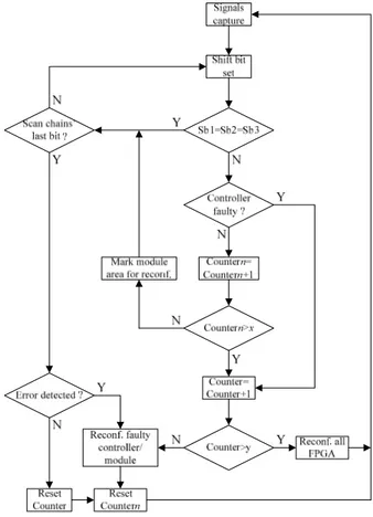
The sequence of tasks followed by the detection-and--fix controller is represented on the flowchart shown in figure 5. This sequence is endlessly repeated in search for emerging faults in the controller or user modules. The serial bitstreams captured through the scan chains are shifted to the internal controller where they are compared, bit-by-bit.
If an incoherency is detected, the module or voter where it was produced is probably not working properly. Obviously, the controller and the scan chains may also be affected by SEUs that may cause their disruption. To prevent it, the controller is implemented using T-TMR and its modules and voters output signals are also covered by the scan chains, creating a self-verifiable circuit. The option of concentrating the controller in only
one area, despite being implemented using T-TMR, was taken to not increase unnecessarily its complexity and the number of occupied CLB columns. However, since it occupies fewer slices than those available in the columns, a convenient separation between modules was implemented.
Figure 5. Detection-and-fix controller flowchart.
The first bits of the scan chain belong to the outputs of the controller. If an incoherency is detected in those first bits, the controller will immediately be full reconfigured. This procedure aims to guarantee the good working condition of the controller. Despite not being a critical component concerning the functionality of the system, its good working condition is mandatory to avoid accumulation of errors and, as a result, to prevent future system failure.
If an incoherency is detected on one of the outputs of one of the modules or voters, the area where it is implemented will be reconfigured after the last bit of the scan chains has been shifted. If several incoherencies are detected in the same module, the module is reconfigured after a parameterizable number of errors, even before reaching the last bit of the scan chains. A new capture is then performed and the verification process restarted.
Of course, if an upset affects the values shifted through the scan chain, this will lead to a wrong fault diagnosis and consequently to an extemporaneous reconfiguration of one of the modules. However, despite
unnecessary, it will not affect the whole system operation.
A more complicated situation happens if the structural configuration of the scan chains is affected by a fault. In this case, several neighboring bits will be disturbed, wrongly suggesting that a general failure in one or more modules is taking place. In addition, to exactly locate the place where the fault has emerged is not possible. Therefore, after the occurrence of a parameterizable number of errors, either in the controller or in the modules, the controller undertakes the full dynamic reconfiguration of the FPGA to completely restore the scan chains.
The exact location of the faulty module or voter enables the controller to activate the partial reconfiguration and to restore its correct functional definition. An external memory keeps the original partial configuration files for the four defined areas. Notice that, due to the volatility of the SRAM-like FPGA configuration memory, this external memory is already necessary to hold the FPGA configuration bitstream to be uploaded during system power up.
The inclusion of a fault detection mechanism brings several advantages to the performance of the recovery procedure. In this case, scrubbing occurs only when its need is identified and on a very defined target, which, having in mind the intervals between the occurrence of SEUs, even in space applications [15], results in considerable power savings when compared with periodic “blind” full reconfiguration.
Even SEUs that do not upset the bitstream, like those affecting flip-flop states that cannot be removed by reconfiguration, will be detected. This means, as mentioned before, that scrubbing by itself can not assure proper work, and TMR is always needed to avoid fault propagation. However, due to the transient nature of upsets, the soft error will be recovered by the circuit in the subsequent update of the affected flip-flop.
5. Case study
To evaluate the effectiveness of our approach, a twenty four-bit counter was implemented, following the rules defined in the proposed framework, in a XC2V1500-based prototyping board. The detection-and-fix controller used a total of 254 slices, distributed by two of the 40 available CLB columns, representing an overhead of 5% in terms of occupied area. Notice that this overhead is constant and independent of the size or the complexity of the systems implemented on the FPGA. The remaining 38 columns were divided in three areas of 12 CLB columns each, leaving a total of 2304 slices available for the implementation of each of the modules of the user’s circuit. The remaining two columns were placed between module areas. Despite not essential to assure a good immunity to column-spanning MBUs, these two columns, which result from the
remainder of the integer division of the remaining 38 columns by the 3 areas, were placed between them to reinforce protection.
The implementation of a TMR circuit in an FPGA may be a hard work, mainly because some design tools are not prepared to implement redundant circuits in an FPGA. As redundant logic seems, at first sight, “redundant”, the first thing synthesis tools do is to eliminate it. Redundant modules and the whole voters may just disappear from the final implementation. In our example, from the initial design, only a simple four-bit binary counter module remained in the end of the synthesis process. To avoid it, design tools have to be instructed to keep hierarchy. In this way, design units will be preserved and not merged with the rest of the design, and redundancy will be kept.
Although flip-flops in configurable logic blocks have programmable features that are selected by configuration latches, flip-flop registers are separated from configuration latches and cannot be accessed through configuration. Therefore, partial reconfiguration does not affect the data stored in these registers, and consequently, as mentioned before, soft-errors in data registers, even being detected when the scan chain is updated, cannot be recovered using this method. During design project it should be assured that all flip-flops are updated at each clock cycle, thus, due to the transient nature of upsets, the soft-error will be recovered by the circuit in the subsequent update of the affected flip-flop. Therefore, if a SEU affects one flip-flop, the fault it generates will be corrected immediately at the next clock cycle. The propagation of soft-errors that affect data registers is avoided by the proper nature of TMR.
The assignment of areas to the different modules and to the detection-and-fix controller is done through the use of placement constraints, attached to the description of the system. These constraints are taken into account by the place-and-route algorithm, when mapping the different modules in the FPGA resources. Manual adjustments may need to be performed on the final floorplanning, as tools are not prepared to deal automatic and efficiently with these constraints.
Each module area enables the implementation of circuits far more complex than the one used to test the proposed approach. The incorporation of the scan chain implied an overhead of 3 slices per module output, necessary to capture the output of the module and the outputs of the corresponding majority and minority voter. Therefore, this overhead depends on the number of outputs of the user system and not of its complexity. In case of fault detection, the detection-and-fix controller triggers the partial reconfiguration of the affected area, by resolving the location address of the file to be configured. Our prototyping board uses SystemAce [21] from Xilinx to keep trace of the partial configuration files and to configure the FPGA. However, different kinds of interfaces may be used to provide the partial
reconfiguration files, including remote sources. The partial configuration files were generated using the Foundation tools from Xilinx.
The dynamic reconfiguration of part or whole of the FPGA configuration memory does not affect the normal operation of the functions whose functionality is not changed, even if these functions are in an active state and its placement area is covered by the reconfiguration. In sum, the mitigation procedure is completely transparent.
The maximum speed of operation achieved by the detection-and-fix controller was 200MHz. Since capture operations must be synchronous with user’s system operation, any speed below this one may be used.
Several tests based on localized fault injection through partial reconfiguration proved the effectiveness of the proposed concept. However, a random fault injection procedure is being developed to better simulate real working conditions.
6. Conclusion
This paper presented a framework for the confinement, detection and mitigation of induced faults in FPGAs, built around a customised TMR implementation. Several issues related to the effectiveness of TMR to cope with radiation and electromagnetic interferences induced faults were reviewed and discussed. It was explained, based on a compilation of experimental data reported by several authors, why T-TMR associated to scrubbing seems to be the most effective approach to mitigate induced faults in FPGAs and to extend the reliability of the implemented systems. Several techniques were listed to improve the effectiveness of T-TMR implementations, taking into consideration some conclusions extracted from the analysis of that data. These considerations led to some questions and to the enumeration of a set of rules to be followed to get the most from a T-TMR implementation in terms of radiation and electromagnetic interferences induced fault protection. A simple case study based on a practical implementation enabled the quantification of the area overhead introduced and the assessment of the effectiveness of our proposal. Further work is being done to emulate real harsh operation conditions to better evaluate the behavior of the framework.
References
[1] L. Sterpone, M. Violante, “Analysis of the Robustness of the TMR Architecture in SRAM-Based FPGAs”, IEEE
Trans. on Nuclear Science, Vol. 52, No. 5, pp.
1545-1549, October 2005.
[2] M. Ceschia et al., “Identification and Classification of Single-Event Upsets in the Configuration Memory of
SRAM-Based FPGAs”, IEEE Transactions on Nuclear
Science, Vol. 50, No. 6, pp. 2088-2094, December 2003.
[3] M. Bellato et al., “Evaluating the effects of SEUs affecting the configuration memory of an SRAM-based FPGA”, Proc. of the Design, Automation and Test in
Europe Conf., pp. 584-589, 2004.
[4] H. Quinn, P. Graham, J. Krone, M. Caffrey, S. Rezgui, C. Carmichael, “Radiation-Induced Multi-Bit Upsets in Xilinx SRAM-Based FPGAs”, Proc. Military and
Aerospace Appl. of Prog. Logic Devices Conf., 2005.
[5] Oscar R. Gonzalez, W. Steven Gray, Sudarshan
Patilkulkarni, “Analysis of memory bit errors induced by electromagnetic interference in closed-loop digital flight control systems”, Proc. of the 19th Digital Avionics
Systems Conf., pp. 3C5/1-3C5/9, 2000.
[6] G. C. Cardarilli, F. Kaddour, A. Leandri, M. Ottavi, S. Pontarelli, R. Velazco, “Bit flip injection in processor-based architectures: a case study”, Proc. of the 8th IEEE
On-Line Testing Workshop, pp. 117-127, 2002.
[7] J. Arlat, Y. Crouzet, J. Karlsson, P. Folkesson, E. Fuchs, G. H. Leber, “Comparison of physical and software-implemented fault injection techniques”, IEEE
Transactions on Computers, Vol. 52, No. 9, pp.
1115-1133, September 2003.
[8] M. French, P. Graham, M. Wirthlin, Li Wang, G.
Larchev, “Radiation Mitigation and Power Optimization Design Tools for Reconfigurable Hardware in Orbit”,
Proc. of the Earth-Sun System Technology Conference,
2005.
[9] C. Carmichael, E. Fuller, P. Blain, M. Caffrey, “SEU Mitigation Techniques for Virtex FPGAs in Space
Applications”, Proc. Military and Aerospace
Applications of Prog. Logic Devices Conf., 1999.
[10] E. Fuller, M. Caffrey, C. Carmichael, A. Salazar, J. Fabula, “Radiation Testing Update, SEU Mitigation, and Availability Analysis of the Virtex FPGA for Space Reconfigurable Computing”, Proc. Military and
Aerospace Appl. of Prog. Logic Devices Conf., 2000.
[11] F. Lima, C. Carmichael, J. Fabula, R. Padovani, R. Reis, “A Fault Injection Analysis of Virtex FPGA TMR Design Methodology”, Proc. 6th European Conf. on
Radiation and its Effects on Components and Systems,
pp. 275-282, 2005.
[12] M. Rebaudengo, M. S. Reorda, M. Violante, “Simulation-based analysis of SEU effects on SRAM-based FPGAs”, Proc. of the 12th Intl. Conf. on
Field-Prog. Logic and Applications, pp. 607 615, 2002.
[13] M. Wirthlin, E. Johnson, N. Rollins, M. Caffrey, P. Graham, “The Reliability of FPGA Circuit Designs in the Presence of Radiation Induced Configuration Upsets”, Proc. 11th IEEE Symp. on Field-Prog. Custom
Computing Machines, pp. 133 142, 2003.
[14] G. M. Swift et al., “Dynamic testing of Xilinx Virtex-II field programmable gate array (FPGA) input/output blocks (IOBs)”, IEEE Trans. on Nuclear Science, Vol. 51, No. 6, pp. 3469-3474, December 2004.
[15] M. Gokhale, P. Graham, E. Johnson, N. Rollins, M. Wirthlin, “Dynamic reconfiguration for management of radiation-induced faults in FPGAs”, Proc. 18th Intl.
Parallel and Distributed Processing Symp., pp. 145 150,
2004.
[16] M. Abramovici, C. Stroud, C. Hamilton, S. Wijesuriya, V. Verma, “Using Roving STARs for On-Line Testing and Diagnosis of FPGAs in Fault-Tolerant Applications”, Proc. of the Intl. Test Conference, pp. 973 982, 1999.
[17] M. G. Gericota, G. R. Alves, M. L. Silva, J. M. Ferreira, “Active Replication: Towards a Truly SRAM-based FPGA On-Line Concurrent Testing”, Proc. of the 8th
IEEE Intl. On-Line Testing Workshop, pp. 165-169,
2002.
[18] Triple Module Redundancy Design Techniques for Virtex FPGAs, XAPP 197 Application Note, Xilinx, 2001.
[19] P. K. Lala, Self-Checking and Fault-Tolerant Digital
Design. San Francisco, CA: Morgan Kaufman
Publishers, 2001.
[20] IEEE Standard Test Access Port and Boundary Scan Architecture (IEEE Std 1149.1), IEEE Std. Board, June 2001.
[21] System ACE MPM Solution, Product Specification, Xilinx, 2003.