Corresponding author: [email protected]
Electrical Power & Machines Dept., Faculty of Engineering, Cairo University, Giza, 12613, Egypt.
J. Electrical Systems 2-1 (2006): 13-28
Regular paper
Pr a ct ica l Solu t ion s f or H a r m on ics Pr ob le m s Pr od u ce d in t h e
D ist r ib u t ion N e t w or k s
J
E
S
Journal of Electrical
Systems
Harmonic distortion on the power system is a modern concern due to the technological advances in silicon technology as it presents an increased non-linear loading of the power system. The effects of harmonics are well known: customers could experience major production losses due to the loss of supply as an example, on the other hand, harmonic load currents cause the utility to supply a higher real energy input then the actual real power needed to maintain a plant’s production at a certain level. The utility carries the extra transmission losses due to the harmonic currents. Different solutions will be reviewed as concepts for solving certain types of problems related to power quality. Both theoretical and a case study are presented.
Keywords: harmonics, power factor, phase shifting.
1. INTRODUCTION
The proliferation of harmonic-producing loads on the power system continues to increase [1]. Industrial customers are using adjustable speed drives (ASD) throughout facilities to provide improved process control and energy efficiency. Commercial facility loads are dominated by electronic loads and fluorescent lighting, as well as increased application of ASD in HVAC systems. Even residential loads have a continually increasing percentage of electronic equipment (TVs, computers, compact fluorescent lights, etc.). The result is increasing levels of harmonic currents on power supply systems. These harmonic currents combine with the impedance characteristics of the supply systems to cause voltage distortion.
injection of harmonics is needed, similar to approaches used by utilities for penalizing customers with low power factor. Harmonic problems are an international problem.
Standards for harmonics have been developed [2]-[7]. With increasing quantities of non-linear loads being added to electrical systems, it has become necessary to establish criteria for limiting problems from system voltage degradation. Presently, IEEE standard 519-1992 [2] addresses harmonic limits at the consumer and service provider interface. The intent of IEEE 519 is to limit harmonic current injection into power systems and ensure voltage integrity. This standard is manageable and practical when properly applied to industrial and commercial three-phase consumers. However, when IEEE 519 is applied to single-phase system connections, primarily residential consumers, it can become impractical. Furthermore, engineering studies indicate that the cumulative effect of single-phase non-linear loads may potentially cause voltage degradation on power distribution systems even with individual single-phase consumer IEEE 519 compliance.
While the US is a member of IEC and participates in IEC activities, US standards do not necessarily follow IEC standards. IEC standards are, however, the accepted standards in most of the European Economic Community (EEC). Manufacturers that wish to sell products in the EEC must conform to IEC standards [3]-[5].
G5/4 [6] contains recommendations for maximum harmonic distortion to electrical supplies in the UK. It supersedes the well-established G5/3, setting new, tougher restrictions on harmonic voltage distortion and connection of non-linear loads to the supply system. These more stringent recommendations can result in low voltage, that is 6-pulse inverters greater than approximately 40kW no longer being suitable for direct connection to the National Grid electrical supply. Most off-the-shelf, low voltage AC variable speed drives use 6-pulse inverters, which under the old G5/3 standard would have been acceptable up to power ratings of around 75kW.
EN 50160 [7] is confined to the electricity supplied at the supply terminals, and does not deal with the supply system or the consumer’s installation or equipment itself. As the standard deals with the voltage characteristics in public distribution networks, other aspects essential for the supply quality (for instance short circuit power) are not treated in this standard.
This paper presents results of the harmonic distortion levels produced by ASD in industrial plants. The effect of phase shift transformers and detuned filters are investigated and used as methods to reduce the harmonic distortion.
2. PHASE SHIFTING AND HARMONICS
Phase shifting involves separating the electrical supply into two or more outputs, each output being phase shifted with respect to each other with an appropriate angle for the harmonic pairs to be eliminated. The concept is to displace the harmonic current pairs in order to bring each to a 180° phase shift so that they cancel each other out. Positive sequence currents will act against negative sequence currents, whereas zero sequence current act against each other in a three phase system. Recall that triplen harmonics are zero sequence vector; 5, 11, 17 harmonics are negative sequence vectors, and 7, 13, 19 harmonics are positive sequence vectors. Hence, an angular displacement of: • 60° is required between two three-phase outputs to cancel the 3rd harmonic
currents.
• 30° is required between two three-phase outputs to cancel the 5th and 7th harmonic currents.
• 15° is required between two three-phase outputs to cancel the 11th and 13th harmonic currents.
For instance, in the case of two 6-pulse variable frequency drives of similar rating, installing a delta-star transformer (30° with respect to the primary) on one drive, and delta-delta transformer (0° with respect to the primary) on the other drive, gives an angular displacement of 30° between the two outputs, providing the equivalent of a 12-pulse system. On the common supply of both transformers on the primary, phase shifting between the systems will cancel the 5th and 7th harmonic currents. An angular displacement 15° between outputs provides the equivalent of a 24-pulse system, but requires four 6-pulse loads.
The above approach, that is phase shifting non-linear loads, can thus be used to reduce the effects of selected harmonics.
3. DETUNED FILTERS AND HARMONICS
Depending upon the actual system short circuit level, a reactor in each phase may be required. The inductor is sized to take into consideration the actual capacitor bank, S . The capacitor reactance, XC, is
2
C V X
S
= (1)
and the inductor reactance, XL, is
2 C L
X X
h
= (2)
with quality factor , Q,
L X Q
R
= (3)
where
V : Line voltage
S : capacitor bank rating
h : notch frequency
R: resistance of the inductor
In practice a filter is always tuned below the harmonic frequency that it is intended to suppress because [8] the power system frequency may change, thus causing the harmonic frequency to change proportionally, the inductance of the inductor and the capacitance of the capacitor may change. Of these two, the capacitance changes more because of aging and change of temperature due to ambient temperature and self heating, the initial tuning may be off because of finite size of tuning step.
4. CASE STUDY
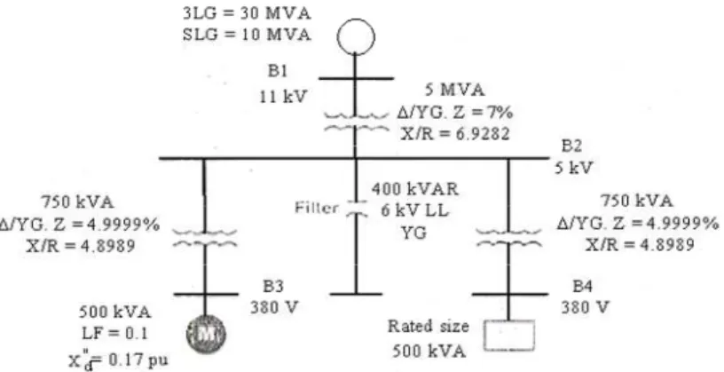
Consider the Industrial plant under study [9] shown in Figure 1. The industrial plant is supplied from bus B2 through main transformer of 5 MVA, Δ/YG, 11/6 kV.
Two transformers each 750kVA, Δ/YG, 6/0.38 kV and capacitor bank 400 kvar are connected to bus B2.
By studying the equivalent impedance of the system at bus B2 , Figure 2, it is shown that there is high resonance point at 7th harmonic which reflects the distortion in the system due to sources of harmonics number 5, 7 and 11.
The harmonics reduction problem is solved on two steps: • using phase shifting technique,
• detuning the capacitor bank.
Figure 1: Industrial plant under study.
Table I: Voltage distortion at bus B2
Harmonic order
Line voltage
(V)
Phase angle (degrees)
% distortion
% Standard
limit
1 5923.924 -2.30 - -
5 1045.031 76.22 17.641 3.00
7 3329.938 -69.35 56.212 3.00
11 179.255 166.83 3.026 3.00
13 58.494 -54.05 0.978 3.00
17 32.876 24.56 0.555 3.00
19 16.046 149.91 0.271 3.00
Table II: Current distortion through main transformer
Harmonic order
Line current
(A)
Phase angle (degrees)
% distortion
% Standard
limit
1 46.477 13.65 - -
5 39.799 -12.76 83.479 7.00
7 88.314 -158.61 190.017 7.00
11 3.025 -102.70 6.510 3.00
13 0.835 36.35 1.797 3.00
17 0.359 -65.15 0.773 2.00
19 0.157 60.17 0.337 2.00
Tables I-II present the line voltage at bus B2 and its harmonics and the line current through main transformer and its harmonics. From the results we can see that the 5th, 7th and 11th harmonic voltages and currents exceed the standard limits of the IEEE Std. 519-1992 [2].
5. STEP 1: USING PHASE SHIFTING TECHNIQUE
ANSI/IEEE C57.12.91 groups three phase transformers into two categories based on the primary-secondary relative phase shift. In category 1; there is 0° angular displacement, this group includes Delta-Delta and Wye-Wye. In category 2; angular displacement is 30°, this group includes Delta-Wye and Wye-Delta connections.
transformer to the 5th and 7th harmonic currents from the Delta-Wye transformer is the cancellation of the 5th and 7th harmonic currents.
Table III: Voltage distortion at bus B2 after changing the connection of one transformer
to Δ/Δ.
Harmonic order
Line voltage
(V)
Phase angle (degrees)
% distortion
% Standard
limit
1 5923.924 -2.30 - -
5 0 0 0 3.00
7 0 0 0 3.00
11 179.255 166.83 3.026 3.00
13 58.494 -54.05 0.987 3.00
17 0 0 0 3.00
19 0 0 0 3.00
Table IV: Current distortion through main transformer after changing the connection of
one transformer to Δ/Δ
Harmonic order
Line current
(A)
Phase angle (degrees)
% distortion
% Standard
limit
1 46.477 13.65 - -
5 0.001 77.25 0.003 7.00
7 0.003 110.38 0.007 7.00
11 3.025 -102.70 6.510 3.00
13 0.835 36.35 1.797 3.00
17 0 24.87 0 2.00
19 0 -29.83 0 2.00
Tables III-IV show a significant reduction in the 5th and 7th harmonics resulted from the application of phase shift transformers. The magnitude of these two harmonics reduced below the IEEE-519 limit. As expected almost no change happened to the 11th and 13th harmonics.
6. STEP 2: DETUNING THE CAPACITOR BANK
From (1), XC =90.0Ω Using h=10.4
From (2), XL=0.832Ω Using Q=50.0
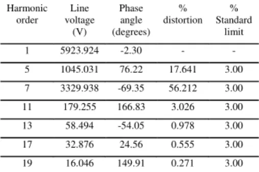
Table V: Voltage distortion at bus B2 after changing the connection of one transformer and detuning the capacitor bank.
Harmonic order Line voltage (V) Phase angle (degrees) % distortion % Standard limit
1 5923.924 -2.31 - -
5 0 0 0 3.00
7 0 0 0 3.00
11 12.438 -36.22 0.210 3.00
13 19.301 120.40 0.326 3.00
17 0 0 0 3.00
19 0 0 0 3.00
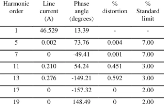
Table VI: Current distortion through main transformer after changing the connection of one transformer and detuning the capacitor bank.
Harmonic order Line current (A) Phase angle (degrees) % distortion % Standard limit
1 46.529 13.39 - -
5 0.002 73.76 0.004 7.00
7 0 -49.41 0.001 7.00
11 0.210 54.24 0.451 3.00
13 0.276 -149.21 0.592 3.00
17 0 -157.32 0 2.00
19 0 148.49 0 2.00
Table VII: Voltage distortion at bus B1 after changing the connection of one transformer
and detuning the capacitor bank.
Harmonic order Line voltage (V) Phase angle (degrees) % distortion % Standard limit
1 10908.279 -1.63 - -
5 0 0 0 3.00
7 0 0 0 3.00
11 16.097 -36.10 0.148 3.00
13 24.978 120.50 0.229 3.00
17 0 0 0 3.00
Tables V-VI show a significant reduction in the 11th harmonic resulted from the application of detuned filters. The magnitude of this harmonic reduced below the IEEE-519 limit. Also, Table VII shows that the magnitudes of all harmonics at bus B1 reduced below the IEEE-519 limit after changing the connection of one transformer and detuning the capacitor bank.
7. VOLTAGE TOTAL HARMONIC DISTORTION
There are several measures commonly used for indicating the harmonic content of a waveform with a single number [1]. One of the most common is total harmonic distortion (THD), which can be calculated for either voltage (VTHD) or current (ITHD). THD is a measure of the effective value of the harmonic components of a distorted waveform, that is, the potential heating of the harmonics relative to the fundamental.
THD is a very useful quantity for many applications, but its limitations must be realized. It can provide a good idea of how much extra heat will be realized when a distorted voltage is applied across a resistive load. Likewise, it can give an indication of the addition losses caused by the current flowing through a conductor. However, it is not a good indicator of the voltage stress with a capacitor because that is related to the peak value of the voltage waveform, not its heating value.
Table VIII: VTHD at the bus B2.
Description VTHD (%) Standard limit
Original case 59.00 5.00
After step 1 3.18 5.00
After step 2 0.39 5.00
Table IX: ITHD in the main transformer.
Description ITHD (%) Standard limit
Original case 207.66 8.00
After step 1 6.75 8.00
After step 2 0.74 8.00
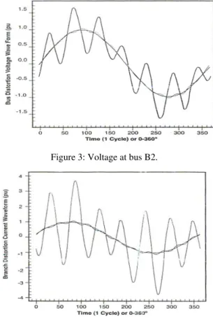
Figure 3: Voltage at bus B2.
Figure 4: Current through main transformer.
Figure 3 shows the difference in the distortion of the voltage at bus B2 before and after using phase shifting technique, and after detuning the capacitor bank. After using phase shifting technique, the voltage distortion decreases from 59% to 3.18% as shown in Table VIII. Also, the 5th and 7th harmonics are cancelled as shown in Table III. After detuning the capacitor bank, the voltage distortion decreases from 3.18% to 0.39%.
Figure 5: Current through two 750 kVA transformers after using phase shifting technique.
Figure 5 confirms this result as one can see the phase shift occurred between the two currents which will make the two current will cancel each other through main transformer. After detuning the capacitor bank, the current distortion decreases from 6.75% to 0.74%.
8. K-FACTOR OF THE MAIN TRANSFORMER
There are different amounts of harmonic currents produced. The term for the total amount of harmonic current present is called THD. Since this value has a wide range, there needs to be an appropriate way to size the K-rated transformer to the load. This is where K-factor comes in. K-rated transformers have an associated K-factor rating. K-factor ratings range between 1 and 50. The higher the K-factor, the more heat from harmonic currents the transformer is able to handle. A standard transformer that is designed for linear loads is said to have a K-factor of 1, whereas a transformer with a K-factor of 50 is designed for the harshest harmonic current environment possible. Transformers rated with K-factors of 40 and 50 are extremely rare, very expensive and generally are not used.
Making the correct selection of K-factor is extremely important because it affects cost and safety. Calculations of harmonic content produces a precise value of K-factor, but power loads change constantly rendering the calculated value questionable.
Sometimes a de-rated K-1 transformer is used to obtain a greater K-rating. For example to achieve a K-13 rating, a K-1 rated transformer would have to be oversized 200%.
Table X: K-factor rating to use when the electronic equipment represents a certain percentage of non-linear current [10].
Non-Linear Load K-rating
Incidental electronic equipment representing <5%
K-1
Harmonic producing equipment representing <35%
K-4
Harmonic producing equipment representing <50%
K-7
Harmonic producing equipment representing <75%
K-13
Harmonic producing equipment representing <100%
K-20
The K-Factor rating, equation 4, is an index of the transformer's ability to withstand harmonic content while operating within the temperature limits of its insulating system.
2 2
1
2 1
(I /I )
(I /I )
h h
h h h K
∑ =
∑ (4)
Table XI: K-factor of the main transformer.
Description K-factor (%)
Original case 36.88
After step 1 1.56
After step 2 1.01
Table XI shows the K-factor values of the main transformer before and after applying the steps of solution of harmonic reduction problem for the case under study.
De-rating a transformer doesn’t assure that it will perform correctly when subjected to non-linear loads. The magnetic and resistive properties of a transformer are enhanced when it is designed specifically for non-linear loads. A standard transformer doesn’t take these considerations into account and may fail even when subjected to light non-linear loads.
Finally, other manufacturers will use aluminium windings instead of copper because it is less expensive. However, to achieve the same resistive property, it takes 1.6 times as much aluminium as it does copper. Since the terminals to the transformer are copper, there is a need to bond aluminium to copper. Achieving strong aluminium to copper bond has been proven to be extremely difficult. Even with a tight bond, aluminium expands and contracts easier than copper due to heat variations, which will loosen the connection. Even though an aluminium wound transformer is initially less expensive, it is larger and more prone to failure than a copper wound transformer and will cost more in the long run.
9. PROBLEMS WITH THREE-PHASE FOUR-CONDUCTOR SYSTEMS
In installations where the neutral is distributed, non-linear loads may cause significant overloads in this conductor due to the presence of the third harmonic. The analysis in this section is based on often-used modern electronic devices fed by a single-phase rectifier with shunt capacitor. These devices are normally connected to one phase and the neutral conductor. The phase currents are non-sinusoidal and therefore contain harmonics. Let us assume that the current waves of the three phases do not overlap. For a period T of the fundamental, a phase current consists of a positive wave and a negative wave separated by an interval where the current is zero. The rms value of the line current can be calculated using the formula:
2
0
1T
S S
I i dt
T
=
∫
(5)/ 3 2 0 1 / 3 T N N
I i dt
T
=
∫
(6)/ 3 2 0 1 3 T N N
I i dt
T
=
∫
(7)2
0
1
3 3
T
N S S
I i dt I
T
=
∫
= (8)Here, therefore, the current in the neutral conductor has an rms value
3times greater than that of the current in a phase [11]. When the current wave of all three phases overlaps, the rms value of the current in the neutral is less than 3times the rms value of the current in a phase. So, a lower supply current from the presented method corresponds to a lower neutral current compared with the uncompensated case.
If we consider that the third harmonic is dominant, the ITHD is very close to the third harmonic ratio. So:
3 1 ITHD S S I I
≅ (9)
3
3
N S
I ≅ I (10)
This can be expressed as:
1
3 .(ITHD)
N S
I ≅ I (11)
Using the general formula:
1 2 1 ITHD S S I I =
+ (12)
We can obtain
2 3.ITHD 1 ITHD N S I
I = + (13)
This approximate formula is only valid when the result is less than 3.
Finally, in installation where a large number of non-linear loads, such as switch mode power supplies for computer equipment, the current in the neutral may therefore exceed the current in each phase. This situation, although rare, requires the use of the reinforced neutral conductor.
9. CONCLUSIONS
A thorough understanding of electrical system related problems will help us implement better solutions. It is estimated in a few years, 70% of electrical loads will be nonlinear. The deterioration of total power factor will therefore mainly be caused by harmonic currents, which affect the distortion factor.
Case study shows that phase shifting does work as promoted, can mitigate harmonics very significantly. Their ability to control harmonics is predicted on how closely matched the individual secondary loads are on the transformer(s).
Therefore, by using the transformers feeding the adjustable speed drives in a smart the harmonic currents need to be cancelled are reduced, which mean, the filter size, if required will be smaller and cheaper.
It is evident that harmonic pollution in a power network is diverse. All ratepayers share the increase in operating cost. Electricity tariffs have to be reflective of all costs incurred. Tariffs therefore have to be based on a comprehensive reflection of the underlying cost to supply electricity. The rate structures as used currently can be modified to more fairly allocate these increased costs.
Finally, Careful considerations are necessary when studying harmonic problems in any power system and on instrumentation requirements for measurements. Important issues must be included as types of loads, power factor characteristics/harmonic generating characteristics, frequency response characteristics of the supply system, power factor correction in the customer facility, and harmonic filters in the customer facility.
Ongoing research effort consists of an evaluation of non-sinusoidal tariff schemes towards a regulatory tariff system for non-sinusoidal power system conditions taking into consideration the above issues.
REFERENCES
[1] R. C. Dugan, M. F. McGranaghan, and H. W. Beaty, Electrical Power Systems
Quality, Mc-Graw Hill, USA, 1996.
[2] IEEE Recommended Practices and Requirements for Harmonic Control in
[3] Electromagnetic compatibility (EMC) - Part 3-2: Limits - Limits for harmonic current emissions (equipment rated above 16 A per phase and below 75 A per phase), IEC 61000-3-12, 2001.
[4] Electromagnetic compatibility (EMC) - Part 3-11: Limits - Limitation of voltage
changes, voltage fluctuations and flicker in public low-voltage supply systems - Equipment with rated current <= 75A and subject to conditional connection, IEC 61000-3-11, 2000.
[5] Electromagnetic compatibility (EMC) - Part 3: Limits - Section 6: Assessment of
emission limits for distorting loads in MV and HV power systems - Basic EMC publication, IEC 61000-3-6, 1996.
[6] Planning levels for harmonic voltage distortion and the connection of non-linear
equipment to transmission systems and distribution networks in the United Kingdom. Electricity Association, UK G5/4, 2001.
[7] Voltage characteristics of electricity supplied by public distribution systems, EN
50160, November 1994.
[8] E. W. Kimbark, Direct Current Transmission, Wiley-Interscience, John Wiley &
Sons Inc., New York, 1971.
[9] A. R. Abou Elwafa , “Principles of harmonic suppression in Industrial Electrical
Systems,” Arab Electricity Magazine, no. 68,pp.20-23.
[10] http://www.controlledpwr.com/products/ultrak/ukkrata1.htm
[11] IEEE Working Group on Nonsinusoidal Situations: Effects on Meter Performance
and Definitions of Power, “ Practical definitions for powers in systems with nonsinusoidal waveforms and unbalanced loads: A discussion,” IEEE Trans. on Power Delivery, vol.11, no.1, Jan 1996, pp.79-101.
[12] J. Schonek, The singularities of the third harmonic, Cahier Technique Schneider

![Table X: K-factor rating to use when the electronic equipment represents a certain percentage of non-linear current [10]](https://thumb-eu.123doks.com/thumbv2/123dok_br/18446134.363741/12.630.140.425.174.356/table-factor-electronic-equipment-represents-certain-percentage-current.webp)
