Evaluation method for safety conditions of buildings
during the structural repair of columns
Método para avaliação da segurança de ediicios durante
a recuperação estrutural dos pilares
T. J. DA SilvA a
N. F. MoNTEiro b
a Professor Doutor, Universidade Federal de Uberlândia – email: [email protected]
b Mestre em engenharia de estruturas, Programa de Pós-graduação em Engenharia Civil. FECIV, Universidade Federal de Uberlândia
email: [email protected]
Received: 28 Oct 2008 • Accepted: 01 Jun 2009 • Available Online: 30 Mar 2010
Abstract
resumo
The structures deteriorate under the action of environmental hazards and other factors and require interventions which can vary from a
simple supericial repair to a more complex reinforcement. The safety analysis in existing buildings differs in several aspects of that estab
-lished in the project, mainly because the parameters generically adopted by the author of the project can be now studied by an investiga -tion on-site at the moment of interven-tion. This work analyzes the safety condi-tions in which the services of structural repair of columns
are made, and it presents a methodology that takes into account the reduction of uncertainties related to resistance and load parameters. The structure of the building is modeled in calculation software in order to obtain a more compatible stress with the reduced analyzed period. The methodology indicates the adjustment of the safety factors together with a global factor of safety for columns that allows the determination of a strategy for repairs to be performed, preserving a probability of failure coherent with the existence of the structure. As a result of the proposed methodology, the part of the concrete and steel sections that will be possible to be removed from the columns in a structural repair of a building due to a process of corrosion that will affect the reinforcement structures or deteriorate the concrete. The methodology proposed was applied to three buildings and one of them is shown in this paper. The structural elements of application were the columns of the garage loor of a 25 loor building with a simulation of a structural repair due to a process of initial corrosion of the reinforcement structures. After the analysis, it was possible to deine the procedure to be adopted for each column.
Keywords: structural safety; column repair; assessment of structures; safety factors.
As estruturas se deterioram pela ação das intempéries e de outros fatores requerendo intervenções que variam de um reparo supericial a um reforço mais complexo. A análise da segurança em edifícios existentes difere em vários aspectos daquela estabelecida em projeto, principalmente porque os parâmetros adotados genericamente pelos projetistas poderão ser mais bem deinidos mediante uma investi
-gação in loco no momento da intervenção. Este trabalho aborda as condições de segurança em que são realizados os serviços de recu
-peração estrutural de pilares e apresenta uma metodologia que leva em conta a redução de incertezas relacionadas aos parâmetros de resistência e de solicitação. A estrutura do edifício é modelada em programas de cálculo, buscando-se obter esforços mais compatíveis com o reduzido período analisado. A metodologia indica como ajustar os coeicientes de ponderação e a obter um coeiciente global de segurança para pilares, que permite traçar a estratégia de execução do reparo, mantendo uma probabilidade de falha coerente com a ex
-istência da estrutura. Como resultado da metodologia proposta, se obtém a parte da seção de concreto e aço que será, temporariamente, possível retirar do pilar, em um edifício em recuperação estrutural devido a um processo de corrosão das armaduras ou deterioração do concreto. A metodologia aqui proposta foi aplicada em três edifícios sendo que um deles encontra-se relatado neste trabalho. Os elementos estruturais objeto da aplicação foram os pilares da garagem de um edifício de 25 pavimentos com simulação de recuperação estrutural devido a um processo de corrosão inicial das armaduras. Após a análise foi possível deinir o tipo de procedimento que seria
adotado para cada pilar.
1. introduction
The structures deteriorate under the action of environmental haz-ards and other factors which require interventions that can vary
from a simple supericial repair to a more complex reinforcement to reach the projected service life. The safety analysis in existent buildings differs in several aspects from those established in the project, mainly because the parameters generically adopted by the author of the project can be now studied by an investigation on-
site at the moment of intervention.
This work presents a methodology for the safety evaluation of col
-umns of existing buildings, during the structural repair, taking into
account the reduction of uncertainties related to resistance and
load effect parameters, starting from adjustments of the design cri
-teria, considering the two basic concepts of the philosophy
semi-probabilistic of safety in the structures: a) the state limits format and b) application of safety partial factors.
The necessary considerations to obtain the resistances and load
effects in the sections of the columns according to updated values will be made in this paper, such as, project values modiied by
inspection results, on-site tests, and studies of adjusted live loads for the reduced period that corresponds to the structural repair, which reduces the relative uncertainties of the evaluated structure.
The methodology still allows a more lexible adoption of the con
-sideration coeficients to be used, due to further knowledge of the inluential variables in safety.
The evaluation efforts, coming from the updated parameters of the building, will be generated by commercial calculation software. Therefore, it is possible to utilize any program that accomplishes
a more sophisticated structural analysis, such as, a
three-dimen-sional frame, considerations of second order global effects, out of
plumb effects, etc.
At the end of this procedure there will be a resistance closer to the real value in the sections of each column under a process of repair, as well as the more probable efforts that will appear in the
short period of repair of those structural elements. Comparing the
active loads and the resistances at the moment of intervention, it is possible to draw a plan for the retreat of the deteriorated
con-crete maintaining an acceptable level of safety for the pieces under
study. In the same way, it will be possible to identify the pieces that
will need shoring during the repair works.
In the structural evaluation, three situations regarding the available documentation are found in general:
a) buildings with complete construction plans, technical speciications, material certiication (concrete and steel
control) etc;
b) structural project only;
c) Intermediate situation with partial documentation.
In relation to each one of these situations, the necessary tests and
studies should be programmed to obtain the information that al
-lows for a better understanding of the building structure. However, there are extreme cases in which there is not any construction re
-cord available, besides the structural projects. Such a situation is not encountered in this work, because, in such cases, the expert involved should deine a particular procedure, with the accomplish -ment of a detailed inspection to supply the complete absence of
data regarding the structure.
The methodology here proposed was applied to three buildings
and one of them is shown in this work. The 25 loor building had it construction paralyzed and the structure was exposed during 10
years which induced the steel corrosion of several structural ele-ments, in which some were columns. The elements analyzed were
the columns in the garage loor which underwent a simulation of
structural repair, because it was not in service yet, due to a process
of initial steel corrosion. After the analysis, it was possible to deine
the procedure type that would be adopted for each column. The repair of the columns was accomplished simultaneously with the
execution of the superior part of the structure. However, it was not
necessary to consider the results of the analysis because the
ac-tive load was inferior to the one of the project considering that the building was under construction.
In the other building on which the methodology was applied, which
has been in service for more than 20 years, the repair of the
col-umns of the garage was executed on the building in use. In this building it was more interesting to demonstrate the validity of the methodology, though, because it indicated the need for shoring in 4 columns, due to contractual reasons, it won’t be shown herein. For the same reasons, the last building in service, on which the methodology was successfully applied and the repair was accom -plished, it will not be shown here either.
2. Considerations on Structural Evaluation
The structural evaluations, according to Ellingwood (1996), are determined in several circumstances, such as: change of occu
-pation of buildings; concerns with materials or defective construc
-tive methods; mistakes found when comparing the project and the building itself after it was occupied; structural deterioration due the normal use or environmental conditions; structural damages after extreme events and users’ complaints due to the service condi -tions. One of the characteristics that differs the safety evaluation of
existent buildings from that established in design, is the possibility
of reduction of uncertainties in relation to the inherent variability of the parameters involved in the load-effect/resistance mechanisms
(ACHE, 2003).
The project guidelines deined by the Brazilian Code ABNT NBR 6118:2003, or other design codes, are not applied directly to the
evaluation of structures, because of the distinct approach of
uncer-tainties. According to Val & Stewart (2002), the design uncertain -ties appear from the previous establishment of load parameters
and resistance for a “generic” structure that has not been built yet. Such uncertainties represent the variability found in many struc -tures, mainly due to the quality of the materials, construction prac-tice, manpower and the variability of the live loads in time, etc.
Thus, the design rules should be conservative to contemplate a
variety of situations.
A particular existent structure is evaluated and it can be inspected and tested, which signiicantly reduces the uncertainties that were considered in design (COST 345, 2004; MELCHERS, 2001). Al
-though the inspection and the tests introduce mistakes and doubts regarding the measured values, for the simple fact that the structure presents a relative quality in the materials, as well as in its execution, a reduction can be expected in its variability when compared to the “generic” structure. This should be taken into account in the safety
ted to an evaluation. Basically, the difference is in the period of time involved in the estimate. For evaluation purposes, the time used,
is the time spent on the repair of columns situated in the garage of buildings, as already pointed out. Such interval comprehends a few months and this mainly affects the loads with signiicant tem
-porary variation (ACHE, 2003). Therefore, in this study a format for estimating the safety will be adopted in consonance with the level B format, previously mentioned, by using the criteria of state limits and partial factors of safety. The updating of the resistance param -eters and load effects at the moment of the analysis will be done,
and the observation period will be extended according to necessity
for the structural repair.
3. Methodology Proposal
The proposed methodology uses some studies carried out in
structural repair which point to the use of rules and similar
for-mats adopted by design codes of most countries, containing the basic guidelines: a) maintenance of state limits and b) application of partial factors of safety (MELCHERS, 2001; VAL & STEWART,
2002).
Other considerations were incorporated to the methodology, for instance, the one suggested by Allen (1991) who proposes that an evaluation criterion should be delineated according to more speciic situations than the design criterion and the professional
should consider consequences of failure in certain situations in critical structures. The evaluation should incorporate all the
infor-mation obtained in the inspections, including the performance of
the structure.
Alike other researchers, load effects were compared for the sake
of safety, such as (bending moments and compression loads) that were more probable to occur in the columns of the irst level start
-ing from the foundations, usually in the garage of residential build
-ings, with the effective resistances of their cross sections at the moment of the intervention, through an ultimate limit state equation (LARANJA & BRITO, 2003).
In order to obtain the evaluation load effects, an adjusted structural
modeling was used which was calculated by the program. The ca
-pacity of the current calculation programs in the market (spatial analysis, application of effects of local and global imperfections, wind load, and considerations of second global order effects, etc.), is capable of providing a more precise analysis than that made in the conception, mainly when the buildings are more than 20 years old. In garage columns, the evaluation load effects obtained by the program, despite its location, will be represented by biaxial bend
-ing moments (X and Y) and axial force.
The irst step of the methodology is to perform the modeling of the existing building, taking into account all of the deined aspects in projects, delineating the behavior of the structure in a computer -ized simulation for more reliable results. After the application of the software, it is convenient that the reactions obtained in the foun-dations are closer to the project, because those were the
reac-tions by which the structure was designed and executed. Thus,
adjustments should take place in the continuity of the structure, in order to approach the reaction values supplied by the structural
de-signer. At the end of the adjustments, the structure modeled in the
software will be similar to the one projected, without the alterations
which were incorporated during the construction, though. in relation to the service life of the residential building (in general 50
years), it is possible to say that the probable values of occurrence for the variable loads (live loads and winds, mainly) will also have a
signiicant reduction from those proposed in the design codes. This
fact will be considered in the safety analysis.
Several works were developed regarding the attempt to establish an acceptance criterion for structures of existing buildings. The ma
-jority of the proposals is related to the adjustment of the guidelines of design codes (ALLEN, 1991; VAL & STEWART, 2002), however, a great progress is observed in the research and application for the bridge structures and other road structures (ACHE, 2003; COST 345, 2004).
The steps in the evaluation process do not present great differ
-ences among the several researchers. Melchers (2001) presents a
typical pattern used for the evaluation process, currently used:
n on-site inspection;
n collection of data and information;
n application of formal outlines for evaluation;
n presentation of results;
n decision.
To evaluate the results of inspection and to judge if the structure is
safe, reliability levels should be established, such as those used for
the design conditions (ACHE, 2003). In the evaluation, there is a lack of data in the long run for structures submitted to the process,
mainly in the case of repair or reinforcements, which constitutes
another dificulty for the elaboration of a normative code. Aiming at a better approach of the current situation of constructed buildings,
it is still necessary to search for the reduction of the conservatism in the treatment of particular parameters of evaluation. This fact
should be lessened with the study, the development and ixation of probabilities of laws that are coherence with the real conditions of each structure appraised individually, according to general results found in the inspection (MELCHERS, 2001).
The acceptable probability of failure for an existing structure is an arduous task as well as in works of calibration of codes. COST 345 (2004) presented four levels for specifying target reliability that can represent the approach form and the calibration of the great major -ity of the codes. Those formats can be applied to the treatment of
investigated structures, according to different methods:
n level A - Global safety factor formats and acceptable stresses.
Level A constitutes a conservative criterion because the
reduction of uncertainties cannot be made.
n level B - Semi-probabilistic load and resistance factor
formats and the use of the criterion of the state limits. The
partial factors are speciied according to the current knowledge of the uncertain parameters. Level B is the core in any modern design code.
n level C – Probabilistic-based format on the reliability index
and probability of failure. These formats present concepts of state limits, but they use numeric methods for the resolution
of complex formulations. Such a format is demanded in more complex analyses in which level B is still conservative.
n level D – Formatswhich take economical order considerations
into account. Basically, they originate from partial safety factors (level B) or the probability of failure (level C), modiied by
economical criteria.
The aim of this research is based on the current efforts made to
-plished with the calculation program used in the modeling of the structure. Starting from the evaluation load effects, proceed to the calculation of the reinforcement of the columns, maintaining the real concrete sections, using the load effect parameters and strengths of the materials with the partial factors for the evaluation.
These reinforcements correspond to the necessary ones for the
column during the intervention period and they will be deined as
As(int).
Usually all of the columns of the buildings are reinforced symmetri
-cally in function of the characteristics of the loads, generated main
-ly by the wind and by the simplicity to be executed. This criterion is common in the design of columns, besides, the version of 1978 of Brazilian Code ABNT NBR 6118 contained a simpliied method for
some load combinations and several researchers present
interac-tion diagrams that allow the manual calculainterac-tion of secinterac-tions to be submitted to the combined axial load and biaxial bending moments
with symmetrical bars.
Thus, an equivalent axial load capacity (Nd), obtained by the sum
of the forces of the concrete and steel, As(int) (stresses multiplied
by the corresponding areas) obtained on design presented similar results in the section such as those from the combined axial load and biaxial bending moments. This procedure can also be applied
to the probabilistic treatment because the solution represents a
safety margin. Therefore, the possible combinations generated in
the random process will be contained in the safety area with a
reli-ability index greater than the minimum acceptable index.
As the strengths of the column materials will be determined by the inspection procedures and accomplished tests, the axial load ca -pacity of the section can be computed by equation 3.
where:
KMOD = modiied factor that takes into account some aspects that
inluence the strength of the concrete in the structure
Ac = concrete cross area of the column fcd = factored concrete compressive strength As = steel cross area on the column
s’sd = steel stress related to 2‰ strain of reinforcement
Equation 3 will be used for the calculation of the sectional load capacity during the intervention Ri considering the existing rein
-forcement in the section and for the calculation of the equivalent
axial load capacity Seval with the reinforcement As(int) determined by
the program. Thus, by using equation 2, the relation between the equivalent axial load and the axial load capacity of the section will be deined and both will be factored by the evaluation partial fac
-tors. The type of intervention to be adopted will be deined by ap
-plying the same equation 3, using the concrete section reduced by
the cut and the bars partially corroded when this happens, which will orientate the works of structural repair. A chart of the
methodol-ogy can be seen in Figure 1.
When the global factor is greater than the unit, even with the small -est reduction of the concrete section, the section will be capable of
receiving the intervention. Otherwise, the necessary shoring should
be provided, which is not included in the scope of this study.
In summary, the program provides the calculation of the necessary Consequently, for use in the evaluation, the deined calculation
model will be used with the input parameters. Those parameters,
not possessing the generic characteristic of structures, hold pe
-culiar considerations of the analyzed case, (LARANJA & BRITO,
2000). Thus, in the treatment of the relative uncertainties of the
loads, the methodology here proposed, foresees the updating of the cumulative distributions, allowing the adjustment of the loads
to value compatible to short periods and the use of live loads mea-sured directly in the structures.
Safety partial factors to be applied for the generation of load effects and resistances of evaluation in the sections will be adjusted starting
from the reduction of the uncertainties of these parameters and the
deinition of a reliability index for the existing structure. This will be made by using the formulations and simpliications utilized by the de
-sign codes for the determination of the de-sign safety factors. The evaluation parameters regarding the loads and their partial factors, deined in function of the short period analyzed for the structural repair, will be introduced into the program that will gen -erate the load effects coherent with the current conditions of the
structure, serving as a base for the safety quantiication. Compar
-ing the load effects generated and the resistances of the struc -ture at the moment of the evaluation, a convenient method can be
drawn to execute the intervention.
The deinition of a coeficient that represents the state of the struc -ture at the moment of the intervention is desirable for an evaluation
method based on the ultimate limit state and on the global factor of quantiication of the safety. A form of relating the load effects and
the resistance of the section at the moment of the intervention is the equation ultimate limit state (equation 1) that will have, for this occa-sion, to relate the load effects and the resistances of the sections. where:
Rd,eval = factored resistance on evaluated column cross section
Sd,eval = factored load effects on evaluated column cross section
By using the same philosophy of the state limits, global safety coef
-icient in the evaluation can be given by equation 2:
where:
geval = global safety factor on evaluated columns
Rk,eval = nominal resistance on evaluated column cross section
Sk,eval = nominal load effects on evaluated column cross section
The bending moments and the compressive axial loads act to
-gether and they can reach their maximum values simultaneously. The bending moments should be taken into account because their effects can cause collapse in repair sections. To obtain a global safety factor that involves only axial load effects it is possible to change the evaluation load effects (bending moment and axial force) in a concentric compressive axial load.
accom-symmetrical bars for the state of existing loads during the repair, usually an axial load and moments (F; Mx; My), are determined,
if considered equal to the resistance of the sections. This allows
calculating a concentric axial load that represents the nominal load
effects on evaluated column cross section in the repair. The real section of concrete and reinforcement will supply the nominal re-sistance on the evaluated column cross section.
3.1 Load speciications on the evaluation
3.1.1 Dead loads
Basically, the dead loads are represented by self-weights of struc -tural elements (slabs, beams, columns, etc.), permanent partitions
(walls, inishings, etc.) and permanent equipment. Laranja & Brito
(2000) mention that in safety analysis on a superior level, it is usual to assume that the load type has a normal distribution, with a mean
value equal to the nominal value and that the coeficient of varia
-tion be between 5% and 10%.
In the structural evaluation, the acting permanent loads can be ob
-tained with considerable precision through the geometric charac
-terization of dimensions in cross sections, thickness of inishings in general, thickness of walls, etc. These geometric variations origi
-nated from the different phases during execution, and they depend
on the construction technique, equipment and quality of the labor
force (DA SILVA, 2002). In the design, they must be protected by
the increase of their nominal values.
By the means of techniques that use chemical or physical
mecha-nisms, it is possible to determine the real speciic weight of the
concrete and other materials involved in the production of the dead
loads. This procedure, together with the dimensions obtained by inspections of geometric characterization of sections, reduces the
uncertainties in the treatment of that load type in built structures
(CABRÉ, 1994).
3.1.2 live loads
The live loads presented in design codes, incorporate some basic procedures in its deinition, such as the temporary variability that is
the weight of furniture pieces and people in the several occupation changes in the buildings; ii) an intermittent portion of extraordinary active overloads in short periods of time (MELCHERS, 1999). The live load design recommended by ABNT NBR 6120:1980 uses a return period between 140 to 200 years, with a low occurrence probability during the service life of the structure (between 25% and 35%). The conception of nominal values for these loads is based on extreme value type 1 distribution, and can result in the adding of the two components of the temporary variability accord
-ing to the rule of Turkstra (COROTIS et al, 1981):
n quasi-permanent maximum value in the service life, added to the temporary maximum value in an occupation;
n temporary maximum value in the service life, added to the
quasi-permanent value in an occupation;
n adding of the maximum values, in service life, of both
components.
Considering the extremely reduced time interval, as in the the
structural repair of columns, the live loads will be basically
restrict-ed to quasi-permanent component (ELLINGWOOD, 1996). Basrestrict-ed on other authors’ data, Corotis and Doshi (1977) analyzed the col
-lected data of instantaneous live loads in buildings, obtaining the gamma distribution, as a better adjustment. This function was used by Hahn and Shapiro (1969), which presents the general formula
-tion of the cumulative gamma distribu-tion by equa-tion 4.
where:
FL = cumulative distribution function
x = random value Γ (η) = gamma function
λ e η = parameters of distribution function
For integer values of η, the function gamma is transformed in to equation 5.
Using the expressions for λ and η presented by Hahn and Shapiro (1969) and the data of residential buildings obtained in data collec
-tion, for instance, with the mean of 0.544 kN/m2 and standard
devia-tion of 0.193 kN/m2 one can obtain the cumulative distribution
func-tion, equation 6, to live loads (quasi-permanent) instantaneous.
Monteiro (2006) used equation 6 and integrated it with inspection data presented by Corotis and Doshi (1977), according to an ac
-cumulated value of 95% (characteristic fractile), found, for the in -stantaneous live loads for the short periods of structural repair, the
value X95% = Fq,eval = 0.875 kN/m 2.
3.1.3 Wind loads
The Brazilian CodeABNT NBR 6118:2003 requires that forces
caused by the wind ought to be taken into consideration when de
-signs are carried out. In the previous version of the code, this was not necessary. Although the buildings were projected using the
previous version of the code, the reduced computer time required
by the current programs, to analyze the horizontal forces in build
-ings, the evaluation in the repair interventions were allowed, such
effects will always be considered.
The loads introduced by the wind are calculated from the pressure
generated by the basic speed (V0). It is a representative value of a “3 second gust” with a probability of 63% of being exceeded once, on average, in the period of 50 years.
In the modeling of the incidence of the wind, according to Turkstra & Madsen (1980), the use of the gamma function distribution on the collected data by anemometers, is satisfactory in the speciied ob
-servation periods. Melchers (1999) adopts the extreme value type I distribution as a good approach to represent such phenomenon. In the present work, the use of the factors developed by Rosowsky (1995) is proposed. They are capable of converting wind speeds of periods of 50 years to other periods, according to the purpose of the evaluation. In the determination of the adjustment factors, Rosowsky (1995)
used an analysis of wind speed data obtained at airports as a refer-ence. This composed the basis of the formulation of winds for
de-signs under the North American codes. Table 1 presents the values
obtained by the researcher for the adjustment of the basic speed.
From Table 1 and knowing that the repair services are, in gen
-eral, of the order of a few months, one can adopt Sadjust as equal to 0.80. This generates equation 7 to determine the value for the
nominal speed of the wind for evaluation.
Where as:
Vk,eval = nominal wind speed in evaluation
3.2 Considerations on material strength
in evaluation
3.2.1 Steel strength
In steel yield tests, when their results are up to design values, they won’t be used in the updating and considerations on steel yield prop
-erty in the evaluation. Thus, for reasons of safety warranty, the strength to 2‰ strain will be adopted for evaluation (σ’sd,eval = 420 MPa) or the
same strength used in design. In the cases of lower results than those in the designed nominal face value, such information will be taken into account because it is an attempt against safety.
3.2.2 Concrete strength
The concrete compressive strength is one of the problems faced by engineers during evaluations, due to the need of measuring the
potential safety presented by the evaluated structure. Basically, the
complexity of the behavior of this material in service over time is due to two evidenced phenomena (FUSCO, 1993):
n increase of strength due to the slow hydration;
n loss of strength due to the sustained loads.
Both phenomena, together with the inluence of the specimen
dimensions, compose the partial factor to compressive concrete
strength (KMOD). This factor should be taken into consideration in
design to avoid that structures collapse because of exhaustion of the resistant capacity during a certain period of its life cycle. The compressive concrete strength in evaluated structures usually follows two obtaining procedures: a) extrapolations based on the control concrete data during the construction, taking into account the age and the effect of sustained loads; b) tests in drilled cores in case no results of concrete control exist, considering, however,
the effect of duration of the loads. In any of the ways, one can use additional tests such as sclerometry and ultrasound scan.
The effect of the sustained loads in the loss of concrete strength refers to the slow propagation of cracks in the matrix of the hard -ened paste. The phenomenon, which initially was studied by Rusch
(1960), happens for load effects that generate strengths above 70% of the strength obtained by standard axial tests in concrete
specimens. For values below this limit, the material presents stable
strength, in spite of the occurrence of creep.
In relation to the variability of the concrete strength, in general, the
reduced number of specimens or drilled cores constitutes a barrier
for the necessary estimate of the coeficient of variation (δc). This
parameter is important because it constitutes a measure of disper-sion of the values of this random variable and contributes for the
estimate of reduced partial factor in the concrete strength. By such facts, a usual procedure consists of the execution of tests of
sclerometry or ultrasonic pulse on the concrete of the studied elements
for the veriication of δc. The objective of using the sclerometry test par
-allel to axial standard tests of specimens is to help in the obtaining of
additional information that can reduce the possibility of mistakes in the
evaluation of several properties of the concrete (ALCÂNTARA, 2002). The use of the ultrasonic pulse test is indicated for deinition of the char
-acteristics of the concrete, its homogeneity and even the compressive strength. With the results of these non-destructive tests and the use of the Bayesian updating, one can improve the representativeness of the group of information already existent which are derived from the speci
-mens or drilled cores (VAL & STEWART, 2002).
In the determination of the concrete strength in existent structures,
two situations are frequently found:
a) Existence of technological control
The structures that nowadays go through interventions for rehabili -tation, are, in most of the cases, more than 20 years old, for which,
the estimation of the current concrete strength, demands the use of speciic evolution strength curves of cements used at that time. The Model Code CEB 1990 presents an equation for the estimation of the evolution of the concrete strength over time, by which one
can obtain KMOD1. The Brazilian Code ABNT NBR 6118:2003 also
allows the application of a similar equation 8, that can be applied to the speciied compressive strength (fck,est) obtained by compression
test of control specimens at the time of construction, when one
wants to obtain the strength at the end of a given period of time:
where:
KMOD1 = factor related to concrete strength (related to 28-day-old
strength)
fc,t = “t”-day-old concrete strength fc,28 = 28-day-old concrete strength
S = coeficient that depends on cement type. The following equiva -lence is permitted:
S=0.2 to cement ARI (high early strength) S=0.25 to cement CP I, CP II grade 40 S=0.38 to cement CP III and CP IV
In the evaluation of columns of existent structures, knowing the
dimensions of the cross sections and the loads, it is possible to
estimate the strengths above the limit of 70%, which would cause a reduction of the concrete strength for the Rüsch effect. With this methodology, in consideration of the Rüsch effect, one suggests
that the load effects are the total of the calculation, applied in a
ictitious way, on the 28th day. If the computed determined limit is overcome as such, the reduction in the strength can be calculated by equation 9, extracted from the Model Code CEB 1990. In case
such a limit is not overcome, it will be assumed that KMOD2,eval=1.
where:
KMOD2 = reduction factor to compressive concrete strength to sus
-tained load effect (related to 28 day strength)
fc,t = compressive concrete strength at the age of (t+t0) under high
load and sustained until the t0 age
fc,t0 = compressive concrete strength at t0 age, deined in standard
axial test
The inluence of the dimensions of the tested specimens in the real strength of the concrete, according to Fusco (1993), should
be taken into account in project and structural evaluation. Rusch
by 30 cm of height possesses strength, in general, to the order of 5% larger than the one of the same concrete in the structure. Thus,
one can adopt the relation by equation 10.
In general the smaller the h/d ratio of the specimens, the larger is the obtained strength. A diagram of conversions for other h/d ratios
can be found in Fusco (1993).
Having deined KMOD1, KMOD2 and KMOD3, the KMOD can be composed
by equation 11, emphasizing the importance of the effects of the
behavior of the concrete over time for the evaluation:
The concrete compressive strength to use in this case is given by
equation 12:
where:
KMOD,eval = factor of compressive concrete strength in evaluation fck = speciied compressive concrete strength at the age of 28 days
gc,eval = strength reduction factor in evaluation
b) Inexistence of technological control
The technological control of the materials has been necessary for all of the works for many years, as well as the ile of the whole docu
-mentation. However, few buildings have conserved the documenta -tion, or the entire control was not always accomplished. In these
cases, the extraction and tests of cores must necessarily proceed directly from the studied columns. The lots are taken into agreement with the Brazilian Code ABNT NBR 7680:2007, of those which, de
-pending on the size of the sample, allow obtaining relative conclu
-sions about the concrete strength submitted to the evaluation. The Rusch effect should be evaluated assisting to the same crite
-rion of situation “a”, analyzing the limit of 70% of the strength ad
-mitted by the cylindrical specimens after the 28-day-old process. The relative inluence of the dimensions of the drilled cores is quite ac -centuated for this situation, as not always a relationship h/d=2 is attained.
The diameter of the core should not be less than three times the aggre
-gate diameter, or less than 10 cm. The ABNT NBR 7680:2007 presents a
table for the correction of values for several h/d relationships.
3.3 Considerations on safety factors
are relected in the partial factors (ALLEN, 1991). According to
Montoya et al (1973), in the structural safety establishment, which
are accomplished with simpliied considerations of level B. The
several causes of mistakes and uncertainties in which there is
some knowledge, are attributed to two variables: resistance of the
materials and the value of action taken. The characteristic values of the mentioned variables are considered by partial safety factors,
in order to take into account the remaining random factors that in
-luence the process, about which, knowledge is still incomplete. Val & Stewart (2002) point to an adjustment of these partial factors in the evaluation for the updating of the distribution functions of the vari -ables by them factored, by means of inspections and tests on site, with consequent reduction of the uncertainties inherent to them.
3.3.1 Target reliability index of existents structures
The founding of the reduction factors retake, besides the variability
assumed for the actions, a probability of failure (Pf) acceptable for the
structures and which is implicit in design codes, under the form of a re
-liability index (β). In projects of new buildings, the value of β is close to 3.8. In some countries, the values of β are close to 3.5 (Pf=2.33x10⁻⁴) (COST 345, 2004). In Brazil, during a process of reliability analysis in structural elements designed with the Brazilian codes, Santos & Eboli (2006), found that few were the accomplishments in which the reliabil
-ity index β = 3.8 was attained. In the graphs presented by the authors, it was veriied that, for columns of buildings, with a permanent load/ total_load relation, close to 0.85, which is a relation usually found, the value of β = 3.5 was also less attained.
It has been outlined that the founding of a probability of acceptable
failure for the calibration of future evaluation codes is necessary, and that it be coherent with the current situation of the structure and its
per-formance, presented until the moment of the evaluation,(MELCHERS,
2001). As a certain work was done in order to obtain partial factors
for the evaluation of structures of bridges and existent buildings, it’s possible to assume that the consideration of the same β used in proj
-ect (Val & Stewart, 2002) is satisfactory. A similar consideration was proposed in a work in which the index of acceptable reliability in the
evaluation should stay closer to the value presented by the structure
when built (Tanner, 1995).
Due to the fact that existing structures presented satisfactory
performance, at the same time in which they were inspected in a careful way, the evaluation criteria for these should not be as
con-servative as those in the project of new buildings (ALLEN, 1991).
This fact induced the author to introduce different levels of safety
for existing structures, through adjustment done with the individual contribution of the factors given in Table 2.
Such a procedure demands common sense on behalf of the struc
-tural engineers responsible for the evaluation (Laranja & Brito, 2003), as well as involving a subjective criteria as inspection qual
-ity and probabil-ity of personal risks. However, the method allows determination of the reliability index in the evaluation (βeval) starting
from the β of design, applying some reduction terms that vary from one structure to another, according to equation 13:
where:
Δ = contributory factor to adjustment of the reliability index for
structural evaluation
β = design reliability index
βeval = reliability index for structural evaluation
For the evaluation of columns in existing structures with steel cor
-rosion, detected in a routine inspection, a reliability index could be reduced, in agreement with the methodology proposed by Allen (1993), resulting in the value of 3.25 (Pf=5.77x10⁻⁴).
3.3.2 Safety factor to load effects
a) Dead loads
With the reduction of the relative uncertainties to the active perma
-nent loads in buildings, provided by the procedures of measure
-ments and risings made directly in the transverse sections, as well as the lengths of pieces and the characterization of other ixed
non-structural elements, it is reasonable to adopt less
conserva-tive coeficients for the evaluation of a particular structure (VAL & STEWART, 2002).
A reduction in 10% in the partial load factor of the permanent ac
-tions was proposed by Cabré (1994) in his study of the residual life of existent buildings. Using this information for Brazilian reality,
in the evaluation procedure, under precise inspection conditions and tests, the value proposed for the partial factor for permanent actions is:
However, γf,g,eval, would still be admitted, with a value close to 1.2, for structures with residual life service quite reduced, submitted
to geometric characterization, inspections, tests and without the presence of sensitive damages (LARANJA & BRITO, 2000). For the variable actions it’s also possible to reduce the partial fac
-tor when limiting the development of extreme transient loads and when limiting the analysis interval to the short period regarding the
structural repair.
The ACHE (2003) shows the formulation used to obtain the partial factors for the permanent actions in design, considering a normal distribution. Such information, adapted to the obtaining of the coef
-icients for the structural evaluation can be represented by equa
-tion 14.
where:
gG,eval = partial dead load factor in evaluation
bG,eval = reliability index in evaluation
aG,eval = inluence factor for permanents actions in evaluation dG,eval = coeficient of variation of permanent actions obtained by
on-site measurements
The average coeficient of variation for dead loads, adopted in de
-sign, is estimated at 10%. An expressive reduction of that param
-eter can be obtained by measurements of the structure (ALLEN, 1991). In this case, according to Laranja & Brito (2003), δG,eval could
taken according to the calibration values for design codes (ACHE, 2003). For a situation as such, α with the value of 0.70 can be adopted (RILEM, 1996).
b) Live loads
For live loads, the inherent variability is represented by a coeficient of variation in a 10% to 30% range (ALLEN, 1991). Val & Stewart (2002), in their work in order to deine coeficients for evaluation, used a 30% value for the coeficient of variation.
The calibration for live loads uses an extreme type I distribution system, as a base (ACHE, 2003). The same calibration is used to adjust the life service of the design (LARANJA & BRITO, 2000).
That distribution function is inappropriate for reduced periods. The
approach is made using a gamma distribution system such as that proposed by COROTIS & DOSHI, (1977).
In the methodology presented here, a 95% fractile transformation is used, which was adopted after the deinition of the characteristic value of the loads, for a 99.5% fractile, according to the implic
-it probabil-ity in the design codes for that partial factor (FERRY-BORGES & CASTANHETA, 1971). Therefore, equation 15 should
be satisfactory.
In which:
gf,q,eval = partial load factor in evaluation
F(x)99.5% = cumulative distribution function to 99.5% F(x)95% = cumulative distribution function to 95%
In the case of live loads, integrating equation 6 for both fractiles (95% and 99.5%) and applying equation 15 to the obtained values, the result for the partial load factors for live loads is γf,q,eval = 1.30.
Due to the variable behavior of load effects, produced by wind forces,
and for being out of human control, is an unsuitable possibility for the reduction of the partial load factor (ACHE, 2003). By the methodology
here proposed, in case this type of action occurs, safety partial factors
in the evaluation will be considered according to the same values es
-tablished in design, as a form of guarantee of minimum safety.
3.3.3 Partial concrete strength factor
The concrete strength given in tests is frequently represented by normal distribution (e.g. FUSCO, 1976; MELCHERS, 1999; LARANJA & BRITO, 2003). The partial factor in terms of a semi-probabilistic method can be deined by equation 16, valid for the normal distribution (TANNER, 1995).
In which:
dR = coeficient of variation of resistances
aR = inluence factor β = adopted reliability index
The inluence factor (αR) is a function of the standard deviation of
resistances and actions, which is in the 0.7 and 0.8 range (RILEM, 1996). In this methodology αR will have the value of 0.75.
Global safety factor for columns
In a simpliied way, it can be admitted that the global safety coef
-icient is measured by the product of two partial coef-icients men -tioned previously. A probable failure in columns due to the materi-als will happen because of low resistance of compressed concrete
(MONTOYA et al, 1973). In that way, the global safety will be es
-tablished by the marginal safety credited to the concrete and the
dominant action, in this case represented by the permanent loads.
In such situations, the structure is safe against possible collapse by the coeficient expressed in equation 17.
According to the design coeficients, recommended by ABNT NBR 8681:2003, the expected global safety for columns in a structure re
-cently built, with γ = 1.40×1.40=1.96 is obtained, using equation 17. This value is in accordance with the conventional range of design, between 1.7 and 2.0 (MELCHERS, 1999). Under the evaluation conditions, new partial factors are deined regarding particular information. A new coeficient of global safety is deined for the columns of the existing buildings studied, starting from the consid
-erations related to the new partial coeficients of safety.
For the evaluation of columns, if the speciic conditions in which the structure of the building is going under structural repair services are satisfactory, the safety global coeficient is given by equation 18. Thus, one can conclude by the success of the services executed, a probability of failure given by the reliability index (βeval).
The coeficient regarding permanent load effects is used be -cause it is related to the principal action in the structural safety
(COST 345, 2004). The value given by equation 18 will be use
-ful for the determination of a general plan to act in the section of the column during the period of the repair services. Starting from the global coeficient γeval, it can be determined the need
of shoring.
4. Deinition of intervention type
The term “intervention type” refers to the cut of the concrete section that will be made during the repair. Although other forms may exist,
four types were considered. After the calculation and analysis of
the global safety coeficient of evaluation deined for the building, it
is decided which repair procedure to adopt:
n establishment of the amount of deteriorated concrete to be
extracted from the section at once, maintaining
pre-established safety terms; or
A general orientation in repair works, proposed as standardization for analysis, is presented in Figure 2.
For the removal of deteriorated concrete portions that guarantees
the perfect asepsis of the bars and the suspension of the corrosive process, it is necessary to remove the material not only from the cover layer, but also from a deeper part of the concrete. It was
con-sidered necessary to remove and perform the scaling of a depth of 1.0 cm in the interior part of the longitudinal bars, which usually re
-sults in a inal extraction depth of 5.0 cm in average (1.5 cm of bar covering, 0.63 cm of tie and 1.6 cm of longitudinal reinforcement). A scheme of the extraction is shown in Figure 3.
The height of removal should be extended to the points where cor
-rosion in the bars still exists. In general, in the garages of buildings, the deterioration extends up to 1.0 m from the loor. This is the usual height for depassivated bars with enough humidity for the propagation of the corrosive process.
In the cases where the cut is bigger than 1.0 m high and there is a need to extract the deteriorated concrete in more extensive strips
of the column, it is convenient to remove the material in parts,
frac-tioning the execution of the service to respect a maximum height
of concrete removal at once, which will be the function of the bar
diameter. This procedure seeks to protect the longitudinal bars against the possibility of local buckling, usually restricted by the
ties and by the concrete cover on the bars.
When the resistance of the cross section of the column allows the
possibility of intervention for the removal of deteriorated concrete,
according to the evaluation loads, it is necessary to regulate the
form of execution of the services. In general, if the global coef
-icient allows, the possibility of cut and removal of material of the
whole section should be discarded. That is because of the
possibil-ity of local buckling of the longitudinal bars in case they remain, at
the same time, without a due concrete cover, even if not very thick.
The intervention is also discarded without shoring when the safety global coeficient is very close to the minimum.
The interventions should always be done by specialized
compa-nies for this kind of service. The indications presented in Figure 3 don’t constitute the only possibilities for execution of the services.
An interaction between consultant and the specialized company
should be developed, which can generate other types or interven -tion schemes. Other considera-tions will still be able to be made in
agreement with the labor force and available repair products.
5. Case Study
5.1 Building “A” characteristics
The building “A” (Figure 4) was designed for 25 loors and it had the construction interrupted on the 17th loor in the year of 1995. Because of the retaking of the works, it was necessary to carry out works of evaluation of the general conditions of the existing struc -ture, because it presented several deterioration indications. This
propitiated the obtaining of the general data used in this research.
For this case, a need for intervention was simulated for the
that the building had been concluded, was in use for several years,
and that the data used, had been obtained especially for such an unreal purpose.
The data for the technological control of the concrete or of the steel
was not available. Only the architectural and structural data from
existing projects were made available for the research. Some gen
-eral information from the building is presented.
n Number of loors: 25
n Floor area (tower): 225.00 m2
n Number of columns (tower): 14
n Concrete strength of columns: 25 MPa (read mix)
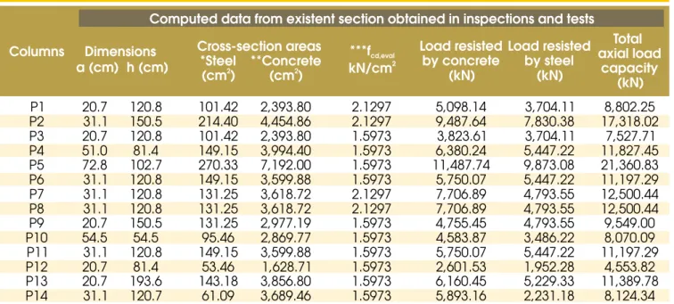
Data from the columns of the main tower are presented in Table 3.
5.2 Field’s data and tests
5.2.1 Geometric characterization of sections
For the geometric characterization, the dimensions of the beams,
columns and slabs were obtained by inspection. The statistical
re-sults were itted in normal distribution. Some data and rere-sults are shown in Table 4.
well as the standard deviations found, came in the range of toler
-ances allowed for the design of new structures.
5.2.2 Concrete and steel strength tests
Because of the inexistence of any registrations of the technological con
-trol of the concrete and steel of the columns, the execution of several tests for the investigation of their real conditions on the current date were care
-fully carried out. With this purpose, there were drilled and tested cores, besides the use of non-destructive testing of ultrasonic and sclerometry. The tested elements included the columns of the garage, beams, slabs
and columns, which served as samples on other pavements.
From the core tests one can calculate the compressive strength of the existing concrete, while the ultrasonic test aided in the estima
-tion of the coeficient of varia-tion. The results for the columns are presented in Table 5.
The number of cores of the sample is in the interval: 6 ≤ n ≤ 20
where as:
n = number of cores of the sample
By applying the Brazilian Code ABNT NBR 12655:2006 to the results shown in Table 5, respecting their particular conditions of use, the
characteristic compressive strength for the evaluation fck,eval = fck,est =
24.66 MPa, was obtained. With the same results, one can also obtain an average of 30.1 MPa and 0.13 for the coeficient of variation.
The results of the statistical calculation of the resistance for the
compressive strength obtained through ultrasonic tests from col
For the columns of the garage loor, the results obtained for com
-pressive strength of the sample were the mean of 24.96 MPa and the standard deviation of 1.94 MPa. These values result in a coef
-icient of variation of 0.08 of the sample that, as already deined, was used as the partial factor of the concrete strength in the evaluation as δc,eval. This value is lower than that obtained for the cores, which
was 13%, but it was considered because the number of tests were higher than the number of cores, and the mean value of compressive strength estimated by the cores and ultrasonic tests, were closer. The tested bars of steel were extracted from the lap splices on the last casting loor (17th loor). Due to the damage already presented in the bars and taking into account that the sample tested probably didn’t correspond to the same steel used in the garage columns, the obtained results didn’t supply effective conditions for evalua -tion. Therefore, these results were not incorporated in the model of uncertainty reduction proposed in this work.
6. Application of the Proposed
Methodology
Following the methodology and starting from the existing structural project, the modeling of the structure was made in commercial soft
-ware program. After several adjustments in the calculations, the
loads obtained in the foundation were satisfactorily closer to the
project loads. The steps for the application of the methodology are
developed as follows.
The obtained data of the inspections and tests, as well as the
stud-ies of the live loads of reduced periods, allowed the obtaining of more appropriate parameters for the structure being studied, ac
-cording to current conditions. On the basis of the methodology pre
-sented previously, the information regarding the building could be updated and it happened in the following manner.
6.1 Material strengths
6.1.1 Concrete strength and factor in evaluation (KMoD,eval)
As already exposed, the concrete strength of the columns of the garage, by the tests made in cores, was of 24.66 MPa, which didn’t cause an increase in the value used in design. In reality, the strength for the tests with cores was lower compared to that proposed in design. Therefore, for the structure in study, the KMOD1
value was 1.0.
The factor KMOD2 was obtained by the analysis of the calculation
loads considering, in a theoretical way, the full application after 28 days. As presented, the reduction of the strength happened in the cases in which the load effect was beyond 70% of the calculation
stress. The load effects were obtained from the model in the
cal-culation program, with input parameters and the resistance of the section of the columns starting from the individual characteristic
resistances of the concrete and steel, lessened by their respec-tive partial factors of calculation. Table 7 presents the results of the analyses.
The KMOD3 adopted for building “A” was 0.95, the ratio h/d of the
drilled cores was in the order of 2.0. Thus, the following KMOD,eval,
(Table 8) were used to modify the concrete strength in case of a necessary safety evaluation of their columns, through equa -tion 11.
6.1.2 Properties of steel reinforcing bars
For building “A” no tests were run for the steel used in the columns of the garage, the same yield strength of design (CA50), a strain
of 2.0‰ and modulus of elasticity of 21 GPa, was used for the
6.2 Actions updating
6.2.1 Permanent actions
The values of the dimensions of the related cross sections were
ob-tained by the characteristic fractile of 95%, using data of geometry of the building structural elements, according to data from Table 4.
6.2.2 Actions due to live load
As an input parameter for the calculation of the evaluation load
effects, only an occupancy load was adopted, according to the ac
-cumulated fractile of 95%, in the adjustment of inspection data by gamma distribution function and given by equation 6.
6.2.3 Actions due to wind load
In the determination of the actions due to the wind, for the speciied period of structural evaluation, a basic speed of 80% of the amount used in the design was admitted. The reduction factor deined by Rosowsky (1995) was used.
Taking into account that the basic speed adopted for design in the city of Uberlândia is 34 m/s, a value equal to 27.2 m/s was ob -tained, for evaluation, within a timeframe of two to three months.
The factors S1, S2 and S3, as well as the drag coeficients, were tak
-en in agreem-ent with those established by ABNT NBR 6123:1988, considering the location of the building and its dimensions.
6.3 Probability of failure
For the settling of the reliability index for evaluation purposes, it was
considered that the need of the supposed intervention had been
deined by a complete inspection of the construction, by which the occurrence of the pathological problem of steel corrosion in all of the columns of the garage, and its deterioration be in the initial
state. It was admitted that these columns possess such duty that
any failure would lead to collapse, putting over 100 people in risk. Considering that in Brazil a deined reliability index doesn’t exist for designs or for existing structures, Table 2 will be used. Considering a study made by Santos & Eboli (2006), a project β with the value of 3.5, which, by equation 13, results in a βeval equal to 3.25.
6.4 Partial materials and load factors
6.4.1 Concrete partial factor
Due to the particular characteristics of the analyzed building, it was
possible to determine new partial factors keeping, however, an ac
-ceptable probability of failure, whose reliability index was deined by βeval.
For the concrete of the analyzed columns, the partial factor was
obtained from βeval and from the coeficient of strength variation,
deined by ultrasonic tests. Considering 3.25 as a reliability index, δc,eval equal to 8% and considering αR equal to 0.80, with the use
of equation 16, a γc,eval=1.10 value was obtained. This value
repre-sents a reduction of 21% in relation to that established for design of new structures. This high reduction was due to the low variation coeficient obtained by the ultrasonic tests and would be advisable to extract a larger number from cores and to use the coeficient of
variation from them.
6.4.2 Steel partial factor
Due to the abscence of technological control in the execution and tests not done with a sample of bars of steel from the garage col
-umns, a partial factor was adopted equal to the design value, that is, γS,eval = 1.15.
6.4.3 Dead loads partial factor
In the case of the permanent actions, in which inspection was
done, the design uncertainties could be reduced. Thus, the coef
-icient of variation of this parameter would be reduced to the value of 5% (ALLEN, 1991). However, the value of 7.5% was adopted in δG,eval to avoid possible mistakes for the standard sampling of
measurements of the structural elements. Using equation 14, with this value, considering the βeval value already deined and using αS equal to 0.75, a γG,eval = 1.19 was obtained.
6.4.4 live load partial factor
For the live loads, the procedure adopted to deine the partial factor was deined by equation 15, in which equation 6 was integrated for two accumulated levels, 95% and 99.5%, according to the deini
-tion of partial live load factor (FERRY-BORGES & CASTANHETA, 1971). Thus, by using the integration, X95% equals 0.875 kN/m2 and
X99.5% equals 1.14 kN/m2, was obtained. With these values, the live loads partial factor for evaluation given by equation 15 was γQ,eval =
1.14 / 0.875 = 1.30.
6.4.5 Wind load partial factor
As previously pointed out, no reduction was applied to the wind load
6.4.6 Global safety coeficient in the evaluation
From previous considerations, the global safety coeficient was de -termined and was to be considered in case the necessity of interven-tion in the columns arose, in compliance with the condiinterven-tions of
build-ing “A”. Accordbuild-ing to the conditions and the available information for the reduction of design uncertainties and using the reliability index (βeval) already informed, the global safety coeficient during the struc
-tural repair of columns given by equation 18, was γeval = 1.31.
6.5 Summary of adopted parameters in
the evaluation
From considerations made for building “A”, based on the theoret
-ical-experimental research and on inspections, the inluential pa -rameters and the values of loads and resistances were lifted for
the evaluation. Table 9 shows a comparative view between design
and evaluation values.
7. results and Discussion
With the necessary considerations made for load effects and re
-sistances of the cross sections in the columns of the building be
-ing studied, us-ing the calculation program, many results were ob
-tained and some partial conclusions were at-tained regarding loads
and resistances.
The inspection demonstrates the there were larger dimensions for sections than those used in the project itself. In general, this increase was around 5%. The total load was 34,987.9 kN, calcu
-lated for the design data, and 36,770.11 kN, obtained from the
evaluation information.
A decrease was veriied in the axial live load value per column, around 40% in average. The same was veriied regarding the ver
-tical actions caused by the wind. In the case of bending moments, that reduction was around 37% in average for X axis, as well as for Y axis.
Table 10 presents the values of the axial loads and evaluation
moments.
Table 11 presents the calculations of the resistances on sections of
the garage columns considered for design sake and the resistances
obtained in the tests and procedures of the evaluation. The latter values represent the real values for repair intervention instance.
After the procedures, the calculation of the garage columns was
done within the evaluation parameters to determine the equivalent
axial load effect. Such calculations were obtained by a calculation program, which had its sections returned to the characteristics de -scribed in Table 12.
The equivalent axial load effect, as already pointed out, acts in the
section for the occasion of a structural repair, taken into account all
particularities considered previously. Thus, this artiice was used to obtain the dummy axial load that produced equal load effects to bending moments and axial loads for evaluation. In this way, it was
considered that the bars of the columns are symmetrical in all of
the cases and the neutral axis is out of the cross section and the
ultimate limit state was reached.
The comparison between the resistance of the section, ob-tained by inspection data (Table 11), and the equivalent load effects (Table 12) for each column, are the basis for the state
limit equation, according to what equation 1 prescribes, should be preserved. In these conditions, when the unit is exceeded by
the application of equation 1, it means that there is the
possi-bility for extraction of deteriorated concrete, taken into account the types of interventions proposed. The computed remaining load was converted into a concrete area to be extracted. Once
the thickness of the cut and stress of the concrete layer is
known, the length of the cut is computed. The results of the
analysis are shown in Table 13.
From the results of Table 13, it is noticed that according to the types of interventions proposed, for 36% of the columns, the intervention type to be used will be I1, for 7%, type I2 for 21%, the type I3 and 36%, type I4. Figure 5 represents the referred percentages.
Since the application of the methodology proposed in this research
was a simulation, a possible loss of cover layer was not considered in the resistance of the sections of columns. In cases of real repair,
the detection of cracking or spalling of the concrete cover layer,
due to the steel corrosion, the total or partial area of the concrete
could be disregarded. In the other two buildings where the meth
-odology was applied, there also was no spalling detected on the