ENGINEERING FACULTY OF UNIVERSITY OF PORTO DEPARTMENT OF MECHANICAL ENGINEERING
Development of a process to obtain a graded
distribution of particles along the overlap of
adhesive single lap joints
Supervisor:
Lucas da Silva
Author:
Catarina Isabel Seixas da Silva
Co-Supervisors:
Ana Queirós José Marques
A thesis submitted for the degree of
MSc of Mechanical Engineering
© Catarina Isabel Seixas da Silva Departamento de Engenharia Mecânica
Faculdade de Engenharia da Universidade do Porto
Rua Dr. Roberto Frias 4200-465 Porto Portugal
i
Abstract
The constant need for improvement and innovation at all industries leads to the development of new technologies. Adhesive bonding is a joining technique in constant growth as, replacing conventional methods of fastening such as bolts and rivets, as it offers potential weight and cost savings.
The adhesive joint most studied and used in industrial applications is the single lap joint (SLJ), mainly due to its simplicity and efficiency. In typical SLJs, however, one of the problems associated with them is the nonuniform stress distribution (shear and peel), being concentrated at the ends of the overlap. This leads to early joint failure, especially if the adhesive is brittle. One of the main areas of investigation in the field of adhesive bonding is the development of methods for reducing such stress concentrations. In fact, functionally graded adhesive joints have been gaining attention as a technique to even those stress distributions along the joint, due to their potential high degree of customization, offering more solutions for application design. Essentially, this method consists of a modified adhesive with properties that vary gradually along the bondline, allowing an enhanced stress distribution along the overlap region.
Therefore, the main goal of this work is to propose a new method to decrease stress concentrations by applying the concept of functionally graded adhesive joints using magnetised cork microparticles. Thereupon, a customized apparatus was designed. With the appropriate application of tailored magnetic fields, using a set of magnets arrays, the magnetised microparticles were strategically placed along the bondline, then creating a particle concentration gradient from the ends of the overlap (higher) to the middle (lower). Numerical models were developed to predict the particle distribution along the joint caused by the application of magnetic fields. Those models were based on the phenomenon of magnetophoresis of cork-magnetite microparticles. A characterisation of the magnetic behaviour of cork and magnetised cork microparticles was also performed. Early experimental tests using glass slides with the particles uniformly distributed within the adhesive selected were performed to validate the simulations.
Mechanical tests were executed to determine the properties of the following composite arrangements: neat resin and resin with magnetised cork microparticles (uniform and graded distributions), considering various amounts. Bulk specimens were used to perform tensile tests and glass transition temperature measurements. SLJs were also done to evaluate the influence of the reinforcement inclusions (magnetised cork microparticles). Simultaneously to mechanical testing, SEM analysis was made in regard to the particles themselves and the bulk specimens fracture surfaces.
ii
Overall, it is concluded that the magnetised cork particles gradely distributed in the overlap region of the SLJ serve as reinforcement inclusions. This way, the newly developed method was validated, along with the apparatus conceived to produce such joints.
Keywords: Epoxy adhesives, functionally graded adhesive joints, magnetised particles,
cork microparticles, magnetophoresis, numerical analysis, stress distribution, mechanical properties.
iii
Resumo
A necessidade constante de melhoria e inovação em todas as indústrias conduz ao desenvolvimento de novas tecnologias. O uso de ligações adesivas está a ganhar destaque como método de ligação estrutural, substituindo métodos convencionais de fixação, tais como a utilização de parafusos e rebites, uma vez que este método potencia reduções de peso estrutural, assim como de custo.
A junta adesiva mais estudada e usada em aplicações industriais é a junta de sobreposição simples (JSS), devido principalmente à sua simplicidade e eficiência. Contudo, na maioria das JSSs, um dos problemas associados é a distribuição não uniforme de tensões (corte e arrancamento), estando estas concentradas nas extremidades da sobreposição. Por sua vez, tal desencadeia a rotura prematura das juntas, especialmente se o adesivo for frágil. Neste sentido, umas das áreas principais de investigação relativamente às juntas adesivas é o desenvolvimento de métodos para reduzir essas concentrações de tensões. Na realidade, as juntas adesivas funcionalmente graduadas têm vindo a ganhar mais relevância como uma técnica para igualar a distribuição de tensões, podendo ser facilmente modificadas para se melhor adaptarem ao carregamento e oferecendo uma vasta gama de soluções a nível de design. Essencialmente, este método consiste em ter-se um adesivo modificado com propriedades que variam gradualmente ao longo do comprimento de sobreposição, permitindo assim a existência de uma melhor distribuição uniforme de tensões nessa região.
Deste modo, o objetivo principal deste trabalho é propor um novo método para diminuir as concentrações de tensões, através da aplicação do conceito de juntas adesivas funcionalmente graduadas, usando micropartículas de cortiça magnetizadas. Portanto, foi projetado um mecanismo para este efeito. Através da aplicação apropriada de campos magnéticos cuidadosamente desenhados, obtidos usando um conjunto de magnetes, as partículas magnetizadas foram estrategicamente colocadas ao longo da sobreposição de uma junta adesiva, criando assim um gradiente de concentração de partículas desde as extremidades (elevado) até ao centro (baixo).
Modelos numéricos foram desenvolvidos de modo a prever a distribuição das partículas ao longo da junta, causada pela aplicação de campos magnéticos. Esses modelos basearam-se no fenómeno da magnetoforese de micropartículas de cortiça-magnetite. Por outro lado, foi também realizada a caraterização relativa ao comportamento magnético de partículas de cortiça pura e magnetizada. Testes experimentais preliminares usando lamelas de vidro com partículas uniformemente distribuídas no adesivo foram realizados de modo a validar as simulações feitas anteriormente.
iv
Testes mecânicos foram executados para determinar as propriedades básicas dos seguintes arranjos compósitos: resina e resina com micropartículas de cortiça magnetizadas (distribuições uniforme e graduada), considerando quantidades variadas. Provetes bulk foram usados para executar testes de tração e medições da temperatura de transição vítrea. JSSs foram também feitas de modo a avaliar a influência de inclusões de reforço (micropartículas de cortiça magnetizada). Simultaneamente aos testes mecânicos, foi realizada uma análise pelo SEM relativamente às partículas e às superfícies de fratura dos provetes bulk.
Globalmente, concluiu-se que as partículas magnetizadas de cortiça distribuídas gradualmente na zona de sobreposição de uma JSS funcionam como inclusões de reforço. Desta forma, o novo método desenvolvido foi validado, assim como o mecanismo concebido para produzir estas juntas.
Palavras-chave: Adesivos epóxidos, juntas adesivas funcionalmente graduadas,
partículas magnetizadas, micropartículas de cortiça, magnetoforese, análise numérica, distribuição de tensões, propriedades mecânicas.
v
Acknowledgements
This thesis would not have been possible without the guidance from everybody listed next. So, for that, I am really thankful for all the help and support you all gave me. To my supervisor, Professor Lucas, I would like to thank, whose expertise was invaluable in the formulation of the research topic.
I am especially thankful to Ana and Zé for their valuable guidance. You provided me with the tools that I needed to choose the right direction and successfully complete my dissertation.
I am grateful to all of those whom I have had the pleasure to work with during this semester. Each of the members of ADFEUP has provided me extensive personal and professional guidance and taught me a great deal about scientific research and life in general.
Also, I would like to thank Vítor Amaral, from CISM (Centre for Imaging and Structure of Materials), University of Aveiro, for providing me relevant content about the magnetic behaviour of the pure and magnetised cork microparticles.
In addition, I want to thank my closest friends, who were of great support in deliberating over our problems and findings, as well as providing happy distraction to rest my mind outside of my research. To Katie and Mário, you supported me greatly and were always willing to help me.
Nobody has been more important to me in the pursuit of my dreams than the members of my family. Therefore, I would like to thank my Parents, Sista, Grandma and Titi, whose love and guidance are with me in whatever I pursue.
Last but not least, this research would not have been possible without the financial assistance provided by Foundation for Science and Technology ( POCI-01-0145-FEDER-028035).
vii
Contents
Abstract ... i Resumo ... iii Acknowledgements ... v List of Figures ... ix List of Tables ... x Nomenclature... xi 1. Introduction ... 11.1. Background and motivation ... 1
1.2. Problem definition ... 2
1.3. Objectives ... 2
1.4. Outline of this thesis ... 3
2. Theoretical background ... 7
2.1. Adhesive bonding as a joining technique ... 7
2.2. Functionally graded adhesive joints... 9
2.2.1. Mixed adhesive joints (MAJs) ... 10
2.2.2. Graded cure... 12
2.2.3. Second phase inclusions ... 15
2.3. Magnetophoresis with cork-magnetite microparticles ... 18
2.3.1. Basic concepts of magnetism ... 18
2.3.2. Magnetic characterisation of the particles ... 24
2.3.3. Magnetophoresis ... 25
3. Development of the experimental procedure... 35
4. Development of an apparatus to produce FGA SLJs ... 43
5. Conclusions ... 45 6. Future work... 45 References ... 47 Paper 1 ... 50 Patent ... 50 Paper 2 ... 50
ix
List of Figures
Figure 1. Example of an adhesive joint (adapted from [2])... 7 Figure 2. Comparison between riveted joints and adhesive joints [2]... 8 Figure 3. Undesirable load types of adhesive bonded joints: (a) cleavage, (b) peel stress (adapted from [6]). ... 9 Figure 4. Schematic illustration of the shear stress distribution of a functionally graded adhesive joints versus a “conventional” adhesive joint. ... 10 Figure 5. Mixed adhesive joint (Adapted from [2]). ... 10 Figure 6. Schematic shear stress distribution at failure in mixed bi-adhesive joints [18]. ... 11 Figure 7. Mixing ratio along the length of an adhesive joint (all dimensions in mm, adapted from [24]). ... 12 Figure 8. Mechanical properties distribution along the overlap of a FGA joint obtained by graded cure [25]. ... 13 Figure 9. Mould with the coil system that allows the graded cure in SLJs (adapted from [28]). ... 14 Figure 10. Cell structure of a cork (a) board and (b) particle (adapted from [31]). ... 16 Figure 11. Illustration of the effect of damping of cork cells: (a) cork cell with resin penetration; (b) cork cell without resin penetration [11]. ... 17 Figure 12. Microstructure of cork microparticles with a size range of: (a)38-53 μm; (b) 125-250 μm [11]. ... 18 Figure 13. Magnetic moment of a planar current loop of current I and area S. ... 19 Figure 14. Field lines of the magnetic induction produced by a magnetic moment. Field lines diverge at the N magnetic pole and converge at the S magnetic pole [53]. ... 20 Figure 15. Typical arrangements of magnetic moments of paramagnetic, ferromagnetic, antiferromagnetic and ferrimagnetic materials. ... 21 Figure 16. When a ferromagnetic divides into domains, its energy decreases as its induction field lines become confined essentially to its interior [55]. ... 22 Figure 17. Typical magnetising cycle of a ferromagnet and corresponding magnetic domain structure. ... 23 Figure 18. Magnetisation curves as a function of the applied magnetic field. ... 24 Figure 19. Pure cork magnetisation curves as a function of the applied magnetic field. 25 Figure 20. Diagram of the forces acting on a magnetic particle within a viscous medium. The y components (out of the plane) are not represented. ... 26 Figure 21. Surrounding atmosphere of the magnet model. ... 28 Figure 22. Permanent magnet considered in the COMSOL model. ... 28 Figure 23. Variation of the flux density across the magnet width obtained from COMSOL simulation with the “Magnetic fields, no currents” module. ... 29
x
Figure 24. Variation of the flux density across the magnet length obtained from COMSOL
simulation with the “Magnetic fields, no currents” module. ... 30
Figure 25. First Halbach array used in the COMSOL simulations. The arrows indicate the directions of the magnetisation of each magnet. ... 30
Figure 26. Simulations results for MA I: (top) magnetic flux density along the overlap length (xz plane); (bottom) colour map of the magnetic flux density gradient on the xy plane... 31
Figure 27. Initial (𝑡 = 0𝑠 ) and final ( 𝑡 = 5𝑠 ) particles distributions obtained from magnetophoresis simulation for MA I. ... 31
Figure 28. Initial (𝑡 = 0𝑠) and final (𝑡 = 5𝑠) particles distributions in xy plane, obtained from magnetophoresis simulation for MA I. ... 32
Figure 29. Wood device used to constrain the magnets during the gluing process. ... 32
Figure 30. Backlight image of a glass slide with particle distribution obtained using MA II... 32
Figure 31. Magnet arrangement MA III. ... 33
Figure 32. Backlight image of a glass slide with particle distribution obtained with MA III. ... 33
Figure 33. Example of a glass slide used in preliminary tests. ... 35
Figure 34.Cure cycle for the neat resin... 36
Figure 35.Cure cycle of the adhesive with 1% of magnetised cork particles. ... 36
Figure 36. Experimental representative curve 𝜎 = 𝑓(𝜀) for the adhesive BetamateTM UN3077. ... 37
Figure 37. SLJ geometry, with 25 mm width (all dimensions in mm). ... 38
Figure 38. Failure load as a function of the overlap length, according to the Goland and Reissner classical analysis. ... 38
Figure 39. Example of bad interface adhesion in an aluminium SLJ. ... 39
Figure 40. Examples of aluminium substrates plastic deformation, for a 25 mm overlap width SLJ. ... 39
Figure 41. SEM image of a fracture surface of a composite resin-magnetised cork microparticles plate... 40
Figure 42. Comparison of the influence of the inclusion between sieved particles and non-sieved particles – Tensile Stress as a function of the strain. ... 41
List of Tables
Table 1. Dimensions of a single BC-14 N52 magnet from K&J Magnetics. ... 29Table 2. Experimentally determined mechanical properties of BetamateTM UN3077. .. 37
xi
Nomenclature
Acronyms
FGA – Functionally graded adhesive FGM – Functionally graded material MAJ – Mixed adhesive joint
SI – International system of units SLJ – Single lap joint
TEP – Thermally expandable particle VMR – Variable mixture ratio
Symbols
B – magnetic induction field vector E – Young’s modulus
F, P – Applied force Fi – Magnetic field vector G – Shear modulus
Gm – Magnetic field torque vector h – Height
H – Applied magnetic field vector I – Current
J – Angular momentum vector
l - Length
M – Magnetic moment per unit volume vector, also known as magnetisation m – magnetic moment vector
r – Distance vector R – Radius
xii S – surface vector
t – Thickness
Tg – Glass transition temperature
Tgꝏ - Post-cure temperature
Uz – Zeeman energy
v – Velocity
V - Volume w – Width
μ0 – Magnetic permeability of vacuum μ – Magnetic permeability ε – Strain σ – Tensile stress – Shear stress ρ - Density - Gyromagnetic ratio ν – Poisson’s ratio η – Viscosity δ - Displacement ∇ - Gradient 𝜒 – Magnetic susceptibility
1
1. Introduction
1.1. Background and motivation
Adhesive bonding as a joining technique is a compelling method of joining materials and structures mostly because of its adaptability and ability to reliably join a large range of materials, as well as the combination of any of these [1-3]. Over the years, this method has been gradually replacing the traditional mechanical fixing techniques (e.g. bolts, rivets, welding), as it provides a smoother stress distribution [4], is relatively cheaper and offers lighter solutions than the others. Nowadays, structural adhesive bonding is a key technology for numerous industrial sectors, such as the aeronautical, aerospace, medical and civil industries [5], mainly because of the constant push for lighter, stronger, more resistant and environmentally friendly materials. For instance, the automotive industry, which has significantly grown its adhesive use in the past years, meets this demand by using customized materials such as composites, which combine different groups of materials to achieve components with excellent strength to weight ratios. Custom adhesives are no exception, with increased electrical, thermal, mechanical (toughness, fatigue, impact or wear) properties being sought.
One of the most used structural adhesives is the epoxy resin (a thermoset polymer) due to its good mechanical, thermal and chemical properties. The epoxy microstructure has a densely cross-linked molecular structure, which is very useful for applications in structural engineering, since it presents high modulus of elasticity and strength, as well as low creep and good thermal strength. However, the same microstructure that provides good properties to the epoxy resin, is responsible for the inherent brittleness (low ductility and toughness) with a low resistance to the initiation of cracks and their propagation. That is, one of the main problems associated with adhesive joints is the existence of stress concentrations (shear and peel) at the ends of the overlap [6], thus reducing joint performance. This is especially valid for the most common joint geometry – the single lap joint (SLJ) [7]. Therefore, a main area of investigation in the field of adhesive bonding is the uniformization of stress distribution along the adhesive bondline, in order to reduce the stress concentration at its ends, achieving stronger and lighter joints.
In the literature, several methods can be found to obtain a more even stress distribution throughout the joint [2, 6, 7], which also allow the improvement of the toughness of brittle adhesives. Among these methods, the most promising is the use of functionally graded adhesive joints [8]. Functionally graded adhesives (FGA) are defined as tailored adhesives which have gradually varying mechanical properties along a desired dimension, thus allowing a more uniform stress distribution along the bondline. Within the field of FGA, some promising new-era technologies are based on the inclusion of micro or nano inorganic (silicates, glass, alumina, etc.) [9] or organic particles [10].
2
Additionally, natural materials (i.e. cork or wood fibres) [11-13] are gaining attention as reinforcements of polymeric matrices due to their unique properties: thermal insulation, low density, low cost and sustainability of the raw material [14].
1.2. Problem definition
The constant need for improvement and innovation at all industries leads to the development of new technologies. Therefore, it is of great interest to further develop new concepts in the adhesive bonding area, such as the theme of functionally graded adhesive joints, which are very promising due to their potential high degree of customization, offering more solutions and options in terms of application design.
The aim of this thesis is to propose an innovative method of producing functionally graded adhesive joints using magnetised cork microparticles.
With an appropriate application of magnetic fields, using a customized apparatus, the magnetised cork microparticles will be strategically moved/placed along the bondline of an adhesive joint, being then non-uniformly distributed along the entire overlap area. This results in a gradual variation of the mechanical properties along the overlap, decreasing the stress concentrations, then leading to a more uniform stress distribution on the overlap region.
Adhesive graded joints obtained by this method are expected to be stronger and more efficient, enabling the work with smaller areas and reducing the structural weight, which is a key factor in several industries.
1.3. Objectives
The main goal for this thesis is to develop and validate a new process to produce functionally graded adhesive joints using magnetised cork microparticles, in order to have mechanical properties that vary gradually along the bondline, thus allowing a more uniform stress distribution.
The specific objectives considered for this thesis were:
• Review the state of the art of functionally graded adhesive joints; • Characterisation of the magnetised cork microparticles;
• Determination of the intrinsic mechanical properties of the selected adhesive; • Determination of the mechanical properties of the adhesive filled uniformly with
3 • Development of an apparatus capable of manufacturing adhesive graded single
lap joints with magnetised cork microparticles;
• Compare, in quasi-static conditions, the graded joints with the reference homogenized joints.
1.4. Outline of this thesis
This thesis consists of a summary, a review paper, a patent and a mechanical characterisation paper.
Paper 1 - J.B. Marques, A.Q. Barbosa, C.I. da Silva, R.J.C. Carbas, L.F.M. da Silva, An
overview on manufacturing functionally graded adhesives – Challenges and prospects,
Journal of Adhesion – Accepted for publication in Journal of Adhesion. Abstract of paper 1
Adhesive bonding is a constantly growing and compelling method of joining materials and structures mainly due to its cost-effectiveness, reliability and versatility. Its ability of joining a large range of materials and capability of reducing the stress concentrations in joining assemblies is preferred, in some situations, over the use of other mechanical joining methods such as riveting and bolting.
In recent years, adhesive bonding has become a key technology among the various industrial sectors, namely the automotive industry due to its constant demand for lighter, more resistant and environmentally friendly materials. Therefore, it is of great interest to further develop this kind of bonding, by developing functionally graded adhesive joints. Functionally graded adhesives (FGA) can be defined as tailored adhesives that have varying gradual mechanical properties along a desired dimension, allowing a more uniform stress distribution along the bondline. Application wise these joints are very promising due to their potential high degree of customization, offering more solutions and options regarding application design.
This overview aims to assess all the current experimental achievements and manufacturing processes in the field of FGA, as well as the complications and concerns that need to be addressed in order to achieve consistent, reproducible graded joints that can later be transferred to industrial applications.
4
Patent – C.I. da Silva, A.Q. Barbosa, J.B. Marques, R.J.C. Carbas, J. Abenojar, L.F.M. da Silva, M.A. Martinez, J.C. del Real, Method and apparatus to manufacture
functionally graded joints using magnetised micro particles – PAT 20191000036260.
Abstract of the patent
An apparatus and method to manufacture graded single lap joints (SLJs) bonding with magnetic particle integrated adhesive, wherein the adhesive is a liquid adhesive and the substrates are non-magnetic substrates selecting from the group consisting of aluminium, polymers, ceramics, wood and derivatives. The apparatus comprising a mould with a bottom part (8) and a top part (5), a plate (7), screws (12) and a device that includes an upper (1) and a lower (1’) magnet holders, and an upper (9) and a lower (9’) male components; wherein the magnet holders (1;1’) contain at least one magnetic array, responsible for creating a static magnetic field, that acts on the adhesive layer to distribute the magnetic particles along the overlap length of SLJs. By use of the method, a beneficial reduction of the stress concentrations is provided to overlap ends, in order to bring more structurally efficient structures
Paper 2 – C.I. da Silva, A.Q. Barbosa, J.B. Marques, R.J.C. Carbas, E.A.S. Marques, J. Abenojar, L.F.M. da Silva, Mechanical characterisation of graded single lap joints using
magnetised cork microparticles – to be submitted in an adhesive bonding field journal.
Abstract of paper 2
One of the main problems associated with adhesive joints is the existence of stress concentrations (shear and peel) at the ends of the overlap, reducing joint performance. This is especially valid for the most common joint geometry – the single lap joint. Therefore, a main area of investigation in the field of adhesive bonding is the uniformization of the stress distribution along the adhesive bondline, in order to decrease those stress accumulations at its ends, achieving stronger and lighter joints.
The main goal of this work was to develop a functionally modified adhesive, where the mechanical properties vary gradually along the overlap. With an appropriate application of magnetic fields, using a customized apparatus, magnetised cork microparticles, initially uniformly distributed within a resin, were strategically placed along the bondline of an adhesive joint, being then non-uniformly distributed along the entire overlap area. This results in a gradual variation of the mechanical properties along the overlap, decreasing the stress concentrations and leading to a more uniform stress distribution on the overlap region. The adhesive stiffness varies along the overlap, being maximum in the middle and minimum at the borders of the overlap.
5 Therefore, the influence of the amount of magnetised cork microparticles was assessed. Tensile tests were performed for bulk specimens and SLJs, along with SEM analysis of the particles and correspondent bulk specimens fracture surfaces. Additionally, glass transition temperature measurements were done. From experimental tests, the inclusion of these particles enhances the joints performance for either graded joints or joints with a uniform particle distribution, when compared to those with neat resin. Also, it is possible to manufacture graded joints with different behaviours, depending on the amount of magnetised particles selected.
7
2. Theoretical background
2.1. Adhesive bonding as a joining technique
Adhesive bonding is a material joining technique which is based on the bonding of two similar or dissimilar materials (adherends or substrates) through the solidification of a polymeric material (adhesive) between them, allowing then the transferring of mechanical force or work across the interface [15]. This geometry configuration is also known as adhesive joint and is illustrated in Figure 1. Therefore, an adhesive is a material that, when applied to the substrates, can join them together and resist separation [6].
Figure 1. Example of an adhesive joint (adapted from [2]).
The increasing application of adhesive joints as an alternative to mechanical joints is related to the numerous advantages presented over conventional mechanical fastening methods, such as bolting and riveting. That is, when establishing a comparison between traditional joining techniques and adhesive bonding, the following advantages can be considered [2]:
• Despite the fact that adhesives have a lower mechanical strength than metals, since it is possible to have a bigger bearing area between the materials, a higher stiffness and a more uniform stress distribution can be achieved, also allowing the reduction of stress concentrations caused by bolts and rivets (see Figure 2); • Design flexibility, with the possibility of bonding different types of materials, or
materials whose properties differ a lot from each other; • Low weight, due to the polymeric nature of the adhesive;
8
Figure 2. Comparison between riveted joints and adhesive joints [2].
However, despite its benefits, there are some disadvantages in adhesive bonding, that are [2]:
• Susceptibility of the adhesives to extreme environmental conditions (high temperature and humidity), due to their polymeric nature;
• In order to avoid bad adhesion, the adherends surfaces that will bond need to be carefully prepared, with the appropriate surface treatments (mechanical abrasion, degreasing with a solvent, chemical etching or anodizing, among others);
• Difficulty on providing quality control, since, in some cases, it requires destructive techniques;
• One of the main goals in joints design is to avoid peel and cleavage stresses (see Figure 3), that are the types of load unappreciated in adhesive joints. Yet, this still is a challenge and an area of intense research;
• The bonding process not instantaneous, thus requiring fastening tools in order to keep the parts in the right position.
9
Figure 3. Undesirable load types of adhesive bonded joints: (a) cleavage, (b) peel stress (adapted from [6]).
In spite of the drawbacks outlined above, such as the non-perfectly uniform stress distribution in adhesive joints, there is enough room for improvements. So, in order to reduce the peel or cleave stresses, several methods have been proposed, over the years, to improve the joints strength. Among those are the use of fillets, adherend profiling and other geometrical solutions. Hybrid joints are another possibility to enhance the bonding performance, being the adhesives used in conjunction with rivets, bolts, or a spot weld, for example. Likewise, more approaches to obtaining hybrid joints have been introduced recently, those being functionally graded materials (FGMs) and functionally graded adhesives (FGAs) [2].
Henceforward, this thesis will be aim attention to the concept of FGAs, since this is the subject under study.
2.2. Functionally graded adhesive joints
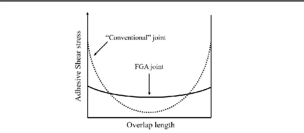
Functionally graded adhesives are defined as tailored adhesives that have varying gradual mechanical properties along a desired dimension, providing a more even stress distribution along the bondline (see Figure 4) [16]. This technique for improving the joint’s performance has been an area of great research and development on the past years, due to not only its substantially high potential in future industrial applications, but also due to the ability of tailoring the stress distribution as desired in an adhesive layer. Therefore, having these features, it is theoretically possible to design high performance structural assemblies with customized properties.
In the literature, the current techniques for manufacturing FGAs are: Mixed adhesive joints (MAJs), Graded cure and Second phase inclusions.
On the next sub-sections, in order to better understand each concept, these three main types of FGAs, listed on the previous paragraph, will be presented in detail.
10
Figure 4. Schematic illustration of the shear stress distribution of a functionally graded adhesive joints versus a “conventional” adhesive joint.
2.2.1. Mixed adhesive joints (MAJs)
Mixed adhesive joints (MAJs) is a technique which combines more than one adhesive, commonly with different behaviours [17-21], along the overlap of an adhesive joint, resulting, ideally, in a gradual variation of properties along the bondline [2, 18, 19]. Accordingly, the concept of MAJs was first introduced with the study of bi-adhesive joints [19, 21], which can be considered a rough version of FAGs [2], since the variation of the properties along the bondline assumes a stepwise behaviour [18, 19, 21], instead of a gradual variation of the properties. In this approach, it is typically used a blend of a stiff adhesive (high modulus) with a ductile adhesive (low modulus), being the first one applied at the centre of the joint and the other one at the edges (see Figure 5) [18, 19]. This provides a synergetic effect [18, 20], allowing the load transfer from the overlap ends, which are the zones of the joint susceptible to stress concentrations [2, 18, 19], to the middle, where a higher strength adhesive actuates for the dissipation of those applied stresses.
Figure 5. Mixed adhesive joint (Adapted from [2]).
Several authors studied bi-adhesive joints [18-21] as a concept of MAJs. From all their experiments, it can be concluded that the performance of bi-adhesive joints is dependent on the ductile-brittle adhesive ratio and on the correspondent position along the overlap.
11 In fact, brittle adhesives provide joint strength, yet they do not take into consideration the all joint length. On the other hand, using too much ductile adhesive, the joint’s strength may lower, but with the right quantity, the load is transferred along the overlap to the brittle adhesive [18]. That is, for a MAJ to be stronger than a brittle or ductile adhesive by itself, the load carried by the stiff adhesive must be higher than the load carried by the compliant one [2]. From those studies, researchers also found out that the quantity of brittle adhesive in the mixing ratio controls the mechanical properties of the joint. That is, for example, by increasing the amount of the stiff adhesive, the Young’s modulus, local hardness and tensile strength would increase too.
Although there have been improvements in the bi-adhesive joints section of MAJs, one of the main problems associated with them is the achieving proper separation of the adhesives (see Figure 6). Due to this fact, even in a joint bonded with several adhesives, the stress concentrations tend to occur locally at the borders between consecutive adhesives (due to the stepwise behaviour), thus leading to joint failure [18]. Therefore, bi-adhesive MAJs can only improve the joints performance up to a certain level.
Figure 6. Schematic shear stress distribution at failure in mixed bi-adhesive joints [18].
Furthermore, another method called Variable mixture ratio (VMR) of adhesives is a more recent technique to manufacture FGA joints based on the concept of MAJs [22-24]. This technique leans on a non-stepwise combination of different adhesives, enabling a gradual variation of the properties along the bondline, which results in a more uniform stress
12
distribution along the overlap [2]. Suitably, there is a continuously change of the mixing ratio of two distinct adhesives, one that is rigid and another one that is flexible, resulting in gradual modulus distribution. Therefore, the mechanical properties of the adhesive joint are greatly dependent on the ratio ductile-brittle of the mixture as well as the respective location along the joint, as it can be exemplified in Figure 7. That is, higher percentage of ductile adhesive leads to a lower Young’s modulus at the correspondent zone; otherwise increasing the quantity of the stiffer adhesive leads to more rigid zones (higher Young’s modulus).
Figure 7. Mixing ratio along the length of an adhesive joint (all dimensions in mm, adapted from [24]).
In opposition to bi-adhesive joints, with the VMR technique there are no local stress concentrations at the borders of consecutive adhesives, which positions this method as an innovative technique, worthy of investment for future industrial applications. Meanwhile, despite improved mechanical properties, thus enhanced joint performance, this method still needs to be better explored in the sense that it should become more general and simpler for future experimental validations and applications. In fact, for Variable mixture ratio of adhesives method, only customized and complex apparatus [1, 22-24] have been developed to produce functionally graded adhesive joints, which turn it difficult to reproduce new adhesive joints. Nevertheless, there is also the question of the difficulty on controlling the mixing ratio, once it is dependent on the adhesives proper selection for mixing, being those apparatus only developed for such adhesives combinations. Therefore, it still does not render feasible the reproducibility of this process, even less its industrial practice.
2.2.2. Graded cure
An alternative way of joint improvement regarding joint strength was accomplished by Carbas et al. [25] through functionally graded SLJs with an adhesive functionally modified by induction heating (the graded cure method). Consequently, the mechanical properties, which are dependent on the adhesive and are function of the cure temperature,
13 vary gradually along the overlap, allowing not only a more uniform stress distribution along the bondline, but also the reduction of stress concentrations at the ends of the overlap. Thus, the adhesive stiffness varies along the overlap, being maximum in the middle and minimum at the ends of the overlap – as depicted in Figure 8.
Figure 8. Mechanical properties distribution along the overlap of a FGA joint obtained by graded cure [25].
Induction heating is an electromagnetic heating method in which electrically conductive bodies absorb energy from an alternating magnetic field, generated by an induction coil. This is a fast technique, since it focuses heat at or near the adhesive bondline, and it is also considered to be very efficient, because the entire assembly does not have to be heated to cure only the adhesive, being the heat generated inside the workpiece [26, 27]. To achieve a tailored differential cure, so that an adhesive with graded properties along the length of the overlap is obtained, a specially developed apparatus for SLJs was designed. Once the induction heating system enables to obtain a graded cure with a focus temperature at the ends of the overlap accompanied by a gradual temperature decrease up to its middle, this apparatus consists of two heating coils (high cure temperature), located at the overlap ends, and a cooling coil (low cure temperature) in the middle part between those two – see Figure 9. Also, a positioning system was built in order to guarantee the correct alignment, geometry, position and thickness of the adhesive layer. The gradient of the temperatures between the middle and the edges can be modified either by changing the induction heating, also known as the alternating magnetic field (e.g. frequency and/or power), or the cooling system (e.g. flow and/or coolant).
14
Figure 9. Mould with the coil system that allows the graded cure in SLJs (adapted from [28]).
In particular, the apparatus enables the production of SLJs with high adhesive stiffness at the centre and minimum at the ends of the overlap, assuming that the adhesive, whose mechanical behaviour is sensitive to the cure temperature, exhibits a ductile behaviour for lower cure temperatures and a more brittle behaviour for higher cure temperatures. Therefore, as presented previously in the MAJs characterisation, this leads to a higher joint strength when compared to the strength of a joint made of an adhesive cured at only one temperature.
For comparison, Carbas et al [25] used the isothermal cure process as a reference for the graded cure results. The adhesives tested in this study were Araldite®2011 and Loctite Hysol®3422. When cured at high temperatures (100, 120ºC), both adhesives showed ductile behaviour and, in opposition, the brittle behaviour appeared when they were subjected to low cure temperatures (23, 40ºC). Overall, the FGA joints were found to have a higher joint strength compared to the cases where the adhesive is cured uniformly at low or high temperatures. In detail, when compared to the corresponding isothermally cured counterparts, the failure load suffered an increase of 68.4% and 67% for Araldite®2011 cured at low and high temperatures, respectively, and an increase of 245.5% and 60.6% for Loctite Hysol®3422 cured at low and high temperatures, respectively. Similarly, regarding the strain, both FGA joints were better or just as good as their non-graded analogues were.
The effect of post-cure (Tg͚ꝏ) on functionally graded adhesive joints obtained by induction heating was also analysed by Carbas et al. [29]. There were considered three different post-curing procedures, for the same adhesives used on the above study. In the first set, the joints were subjected to a curing process only; in the second set, the joints were exposed to a curing process pursued by a post-cure with a temperature bellow Tg͚ꝏ; and lastly, in the third set, the joints were subjected to a curing process followed by a post-cure with a temperature above Tg͚ꝏ. The analysis performed with these different conditions aims to understand the effect of the post-cure, at temperatures related to the glassy and rubbery region, respectively, on the mechanical behaviour of the adhesive joints. The
15 temperatures considered for the post-cure below Tg͚ꝏ regarding the joints bonded with Araldite®2011 and Loctite Hysol®3422 were 60ºC and 40ºC, respectively. On the other hand, the temperature used on the joints bonded with both adhesives was 100ºC.
The performance of the graded joints was measured in relation to the joints cured isothermally. Accordingly, it was found that, for the two adhesives, for a post-cure below
Tg͚ꝏ the joints cured gradually had decreased failure load, instead of those cured isothermally which showed an increase of failure load value. On the other hand, above
Tg͚ꝏ, the joints cured gradually and isothermally tended to present similar failure load values. Therefore, the authors concluded that the functionally customized adhesive properties had been lost when the joints were submitted to a post-cure above Tg͚ꝏ.
Additionally, the main problem that occurs with this technique is due to the thermal bond between dissimilar adherends. In these cases, the high conductivity adherend tends to be heated more by the induced flux than the other component with lower conductivity.
2.2.3. Second phase inclusions
A usual method for enhancing the mechanical properties of adhesively bonded joints is adding a second phase to the adhesive layer which results in a composite material. A composite material is a combination of two or more materials which has better properties than its individual components [30].
This second phase can be a rubbery phase (reaction-induced phase separation) [31, 32] or a reinforcement inclusion, such as fibres, whiskers and particles [31-33], that can enhance either mechanical, electrical and/or thermal properties of the resin matrix.
In this section, reinforcement inclusions in the form of particles will be the main focus. Thus, according to size, particles can be categorized into micro or nano scale and, in terms of nature, they can be inorganic (silicates, glass, alumina, etc.) [9] or organic [10]. Since size is an important material parameter, it is of great importance to establish the difference between micro and nanoparticle inclusions. Therefore, for the same concentration, nanoparticles have higher surface area than microparticles, promoting more particle agglomeration. This is why particle mixing in nanoparticles requires more complex mixing methods (i.e. ultrasound or high shear mixing), instead of microparticle mixing that can be done by using simpler methods (i.e. three-roll milling) [2].
Reinforcement particle inclusions have already been studied in several works. Particularly, some works considered the application of reinforcement nano scale inclusions in the form of carbon based nanoparticles [34]; nano silica; nano clays; amongst others [33]. On the other hand, reinforcement micro scale inclusions investigated in another works have been thermally expandable particles (TEPs) [35], metallic micro materials [36], rubber powders [37] or glass particles [38].
16
Currently, there is a growing interest from the scientific community as well as the industry in using new particles to enhance the joints performance. Depending on the material selected, working with microparticles can lead to less expensive and faster product developments, when compared with other techniques to increase the strength of the joints [32]. Additionally, microparticles are of great interest in the field of FGA joints since they have the potential of being displaced along the overlap, thus creating custom particle distributions, for the various purposes. Consequently, this drives for the obtainment of different properties along the bondline [2].
Furthermore, natural fibres or particles reinforced composites (i.e. cork or wood fibres) [11-13] are an emerging area as they are gaining attention as reinforcements of polymeric matrices, mainly due to their unique properties: thermal resistance, low density, low cost and sustainability of the raw material [14].
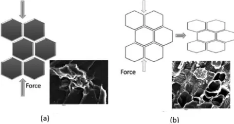
Cork is an organic material with unique combination of properties and can be found in the cork oak, constituting the external covering of its stem and branches [39]. A study made by the World Wide Fund for nature reveals that this biological material is obtained by a truly sustainable process, since it is a renewable and biodegradable source [40]. Macroscopically, cork is characterised by being lightweight, flexible, substantially impermeable to liquids and gases, with excellent thermal, electrical, acoustic and vibration insulation, as well as is an innocuous and imputrescible material (unaffected by microbial activity). In a microscopic scale, cork is described as an aggregation of sealed prismatic cells (see Figure 10a), that work together, displayed in an alveolar structure similar to a honeycomb shape [39, 41-45]. The main characteristics of cork are due from the interaction between the cells as a whole (plank; board or agglomerate). Nonetheless, it was noted that most of the cork properties can also be observed in particles (see Figure 10b) with smaller dimensions [32].
Figure 10. Cell structure of a cork (a) board and (b) particle (adapted from [31]).
Besides that, the properties of an adhesive/cork composite are dependent on various parameters, such as the materials properties; the interfacial adhesion properties between
17 the cork and the resin; size as well as the amount of cork particles and mixing conditions [14].
One possible reason for using cork particles in adhesives is that they act as obstacles to crack propagation, thus increasing the toughness of the adhesive, since the close cells could work together to absorb actively the impact [39, 41, 46]. According to Barbosa et al. [11, 47-49], the inclusion of cork microparticles has proven to be a good reinforcement in brittle adhesives. In the studies performed by the same authors, different amounts of cork and particle sizes were added to a brittle adhesive in order to analyse the influence of those on the behaviour of the cork/resin composite. The adhesive considered in these researches was Araldite2020®, an epoxy resin.
Firstly, it was concluded that the number of cells in a particle is deeply relevant for a good impact behaviour of the cork microparticles (see Figure 11) [11]. These particles are obtained by a milling process which can damage some cell walls, promoting the resin penetration in them. Therefore, the damping effect of the cork particles is decreased, lowering too the absorption of energy. Thus, as it is essential for the cork particles to have a few well-preserved cells, it was identified that above 30μm, microparticles can work as an obstacle to crack propagation, due to cork cell structure; otherwise bellow this value cork has no effect on increasing the adhesive’s toughness, functioning as a defect.
Figure 11. Illustration of the effect of damping of cork cells: (a) cork cell with resin penetration; (b) cork cell without resin penetration [11].
Secondly, the effect of the cork microparticles on the impact properties of a modified epoxy was studied [11]. Experimental results showed that large particles (125-250 μm, see Figure 12b), with well-preserved cells walls, presented better results as reinforcement material compared to small particles (38-53μm, see Figure 12a), with damaged cells walls. On the other hand, 1% of cork particles presents better impact absorption (higher joint strength), comparing to larger amounts, such as above 2% of cork particles in a
18
brittle resin, as well as the resin itself. So, the optimal combination found was to have cork particles ranging in size from 125-250 μm, considering a 1% amount (by volume) of them within the brittle resin [11]. Considering this optimal solution, the experimental results showed an overall improvement of the mechanical properties with better impact energy absorption, when compared to the properties of the epoxy resin itself.
Figure 12. Microstructure of cork microparticles with a size range of: (a)38-53μm; (b) 125-250 μm [11].
Lastly, it was also proved that cork is able to improve the adhesive mechanical properties without detrimental effects on the curing process and on the hydrothermal degradation of the adhesive, regarding the interaction between cork microparticles and the resin [50]. Apart from being a viable technique to enhance the performance of an adhesive joint, this technology also allows to use a product (cork microparticles) that currently is not well exploited by the cork industry. However, new applications are starting to emerge for these particles, although most of them are related to their burning, as they are considered to be an industrial waste. A new purpose for this material would give a new and more sustainable perspective to the cork industry with potential benefits, specially to the Portuguese economy, since Portugal is the world’s leading market for this raw material, accounting for three-quarters of the world’s total production.
2.3. Magnetophoresis with cork-magnetite microparticles
2.3.1. Basic concepts of magnetism
The fundamental concept in magnetism is that of magnetic moment, which is relevant both at the microscopic and the macroscopic scales (e.g., the magnetic moment of atoms or ions versus the magnetic moment of a sample). Magnetic moment is a vector quantity that can be associated to any loop of electrical current. A current loop can be characterised
19 by a surface vector 𝑺 (see Figure 13); the magnitude 𝑆 = |𝑺| represents the loop area; the direction of 𝑺 is normal to the loop and its sense is determined by the sense of the current circulation in the loop. For a current loop with surface vector 𝑺 and electrical current 𝐼, the corresponding magnetic moment is defined as [51]
𝒎 = 𝐼𝑺. (1)
Figure 13. Magnetic moment of a planar current loop of current I and area S.
Microscopic magnetic moments are due to the orbital motions of electrons and their spins. The total magnetic moment of a macroscopic sample is then the sum of all magnetic moments of its constituent atoms or ions. Therefore, a magnetised body has a nonzero total magnetic moment. The SI unit of magnetic moment is Am2 [51, 52].
There is a direct relationship between magnetic moment and angular momentum (𝑱),
𝒎 = 𝛾𝑱, (2)
where 𝛾 is a constant known as the gyromagnetic ratio. This equation implies that any change in the orientation of a magnetic moment is constrained to obey the law of conservation of angular momentum [51, 52].
In the presence of a magnetic (induction) field 𝑩 (SI unit: Tesla, T), a magnetic moment 𝒎 has a magnetic energy, known as Zeeman energy, given by:
𝑈𝑍 = −𝒎 ∙ 𝑩. (3)
This energy is minimum when the magnetic moment is aligned with the magnetic field. For a general orientation of the magnetic moment, the magnetic field will exert a torque on it given by:
𝑮𝑚 = 𝒎 × 𝑩. (4)
By the law of conservation of angular momentum, this magnetic torque will cause the magnetic moment to precess around the direction of the magnetic field. If energy dissipation occurs during this precession, the magnetic moment will eventually reach the equilibrium state of full alignment with the magnetic field. There is, therefore, a natural tendency for magnetic moments to align with a magnetic field [51, 52].
S
𝒎
20
When the magnetic field is nonuniform, the Zeeman energy will change with position, leading to the appearance of a magnetic force given by:
𝑭𝑍 = −∇𝑈𝑍 = ∇(𝒎 ∙ 𝑩) = (𝒎 ∙ ∇)𝑩 + (𝑩 ∙ ∇)𝒎. (5) It should be noticed that because, in general, magnetic moments depend on the applied magnetic field, the spatial derivatives of 𝒎 may be related to those of 𝑩. Magnetic moments are also sources of magnetic field. At distances 𝒓 much larger than the spatial extent of a particle or body with magnetic moment 𝒎, the magnetic induction is of dipolar type, as given by
𝑩 = 𝜇0
4𝜋𝑟3[3(𝒓̂𝒎) − 𝒓̂𝒎], (6)
where 𝜇0 is the magnetic permeability of vacuum, 𝒓̂ = 𝒓/‖𝒓‖ and 𝑟 = ‖𝒓‖. Figure 14 shows the typical distribution of field lines of the dipolar magnetic field produced by a magnet. In the traditional notation, a magnet can be represented by two poles, North (N) and South (S), which define the direction and magnitude of the corresponding magnetic moment [51, 52].
Figure 14. Field lines of the magnetic induction produced by a magnetic moment. Field lines diverge at the N magnetic pole and converge at the S magnetic pole [53].
Two interacting magnetic moments 𝒎𝑖, 𝒎𝑗 (e. g., two magnetite microparticles) separated by a vector 𝒓𝒊𝒋 = 𝒓𝒋− 𝒓𝒊 in vacuum have a magnetostatic energy of the form [52]
𝑈𝑖𝑗 = −𝒎𝑖∙ 𝑩𝑗 = 𝜇0
4𝜋𝑟𝑖𝑗3[𝒎𝑖𝒎𝑗− 3(𝒓̂𝑖𝑗𝒎𝑖)(𝒓̂𝑖𝑗𝒎𝑗)]. (7) where 𝑩𝑗 is the magnetic field produced by moment 𝒎𝑗 and 𝒓̂𝑖𝑗 = 𝒓𝒊𝒋/𝑟𝒊𝒋. The force acting on 𝒎𝑖 by the magnetic field produced by 𝒎𝑗 can be calculated from the negative gradient of 𝑈𝑖𝑗 with respect to the spatial coordinates of 𝒎𝑖: 𝑭𝑚,𝑖𝑗 = −∇𝑖𝑈𝑖𝑗. The total magnetic force exerted on 𝒎𝑖 by its neighbouring magnetic moments is therefore the sum of pair contributions from all other magnetic moments [52]:
𝑭𝑚,𝑖= ∑ 3𝜇0
4𝜋𝑟𝑖𝑗4
21 Since magnetic moment is an extensive quantity, it is usually more appropriate to use a related quantity, known as magnetisation (SI unit: Am−1), which is defined as magnetic moment per unit volume [52]:
𝑴 =𝑑𝒎𝑑𝑉. (9)
According to electromagnetism theory, magnetisation (as happens with magnetic moment) is a source of magnetic field. In a medium with magnetisation 𝑴 under an applied magnetic field 𝑯 (SI unit: Am−1) the resulting magnetic induction is given by:
𝑩 = 𝜇0(𝑴 + 𝑯). (10)
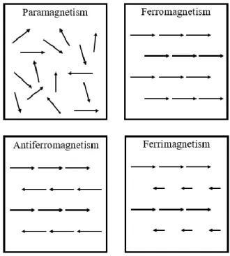
Interactions between electrons are responsible for the large variety of magnetic behaviours of materials [52]. The main types of magnetic behaviour are depicted in Figure 15.
Figure 15. Typical arrangements of magnetic moments of paramagnetic, ferromagnetic, antiferromagnetic and ferrimagnetic materials.
In a paramagnetic material, in the absence of an applied magnetic field (𝐻 = 0), the atomic or ionic magnetic moments are oriented in random directions due to thermal disorder so that the net (spontaneous) magnetisation is zero. When an external magnetic field is applied, these magnetic moments will tend to align themselves in the same direction as the applied field, leading to a nonzero induced magnetisation. For a low applied field, the magnitude of the induced magnetisation is proportional to the applied field, 𝑀 = 𝜒𝐻, where 𝜒 is known as the magnetic susceptibility [51, 54].
22
In a ferromagnet, due to strong electron interactions, the magnetic moments tend to orient parallel to each other, originating a nonzero spontaneous magnetisation. A ferromagnetic sample minimises its total magnetic energy by the formation of magnetic domains (see Figure 16). Inside each magnetic domain, magnetic moments are aligned along a specific crystallographic direction, which differs from domain to domain. As a result, in the absence of an applied field, the total magnetisation may be relatively small, which corresponds to the usually called non magnetised state [51, 54].
Figure 16. When a ferromagnetic divides into domains, its energy decreases as its induction field lines become confined essentially to its interior [55].
The magnetic domain structure can be suppressed by the application of a sufficiently strong magnetic field, resulting in a remarkable increase in magnetisation. Once the monodomain state is achieved and the final domain is aligned with the applied field, magnetisation remains almost constant at a value known as the technical saturation magnetisation (𝑀𝑠𝑎𝑡). After removing the external field, the sample acquires a new domain structure, which is dominated by domains whose orientation are more aligned with the applied field. This results in a remanent magnetisation (𝑀𝑟) and the sample is said to be magnetised. To demagnetise it, it will be needed to apply a reverse field whose value is known as magnetic coercivity (𝐻𝑐) [51, 54]. A typical full magnetising cycle is shown in Figure 17.
23
Figure 17. Typical magnetising cycle of a ferromagnet and corresponding magnetic domain structure.
Because of thermal disorder, every ferromagnetic material has a characteristic transition temperature, called the Curie temperature, or Curie point, above which it becomes magnetically disordered or paramagnetic. Common ferromagnetic materials include iron, nickel, cobalt, their alloys, and some alloys of rare-earth metals. The most powerful permanent magnets are made of rare-earth intermetallic alloys because these materials exhibit high values of remanent magnetisation and coercivity [51, 54].
In an antiferromagnet, electron interactions originate an anti-parallel alignment of neighbouring magnetic moments, giving rise to a zero net magnetisation. Typically, an antiferromagnetic material has two crystal interpenetrating sublattices; magnetic moments in one sublattice are oriented parallel to each other but opposite to the moments of the other sublattice. The anti-ferromagnetic ordering has a critical temperature, known as the Néel temperature, above which paramagnetism is observed [51, 54].
A ferrimagnetic material is similar to an antiferromagnet but the magnetic moments of its sublattices do not exactly compensate each other, so that it has a nonzero spontaneous magnetisation, like a typical ferromagnet. Ferrimagnetic materials also exhibit magnetic domains. Most naturally occurring ferrites, like magnetite, are ferrimagnetic [51, 54]. Every material has, to some extent, a weaker form of magnetism, known as diamagnetism, which is basically characterised by a small and negative contribution to the magnetic susceptibility. Such contribution is usually negligible in materials exhibiting one of the four main types of magnetism. In nonmagnetic materials, such as cork particles, however, the diamagnetic component is dominant [51, 54].
24
2.3.2.Magnetic characterisation of the particles
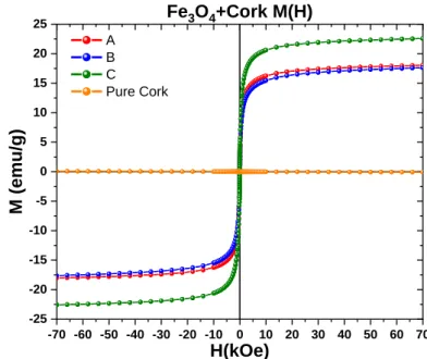
Cork and magnetised cork microparticles of different sizes were magnetically characterized at CISM (Centre for Imaging and Structure of Materials), University of Aveiro. Three particle size ranges were considered: 125-250μm (sample A), 75-125μm (sample B) and 53-75μm (sample C). The magnetic hysteresis cycles (see Figure 18) of the samples were measured at room temperature in the field range ±70kOe (±7Tesla), using a MPMS3 SQUID magnetometer. It should be noticed that an applied magnetic field of 𝐻 = 10 kOe corresponds to a magnetic induction 𝐵 = 𝜇0𝐻 of 1 T.
Particles containing magnetite (samples A, B and C) present a considerable magnetisation, which is fully compatible with the predominant ferrimagnetic behaviour of magnetite. The 𝑀(𝐻) curves were normalized by the whole mass (cork+magnetite).
Figure 18. Magnetisation curves as a function of the applied magnetic field.
The saturation magnetisation, 𝑀𝑠𝑎𝑡, of the cork-magnetite samples is size-dependent: samples A (125-250μm) and B (75-125μm) have a saturation magnetisation of about 18.1 and 17.6 emu/g, respectively, while sample C (53-75 μm) has a higher value of 22.6 emu/g. These saturation values correspond to only about 19, 20 and 25% of the expected magnetisation of a pure bulk magnetite crystal, neglecting the mass of cork present. The changes in 𝑀𝑠𝑎𝑡 with particle size may be related with differences in the relative amount of magnetite and cork present for different particle sizes.
As expected (see Figure 19), the pure cork sample exhibits a diamagnetic behaviour, characterised by much lower values of magnetisation and a negative linear response to the applied field.
-70 -60 -50 -40 -30 -20 -10 0 10 20 30 40 50 60 70 -25 -20 -15 -10 -5 0 5 10 15 20 25 M (emu/g) H(kOe) A B C Pure Cork Fe3O4+Cork M(H)
25
Figure 19. Pure cork magnetisation curves as a function of the applied magnetic field.
From these measurements in such broad magnetic field range, an estimate of the coercive field (needed for zero magnetisation) cannot be done with accuracy. Nevertheless, considering the typical field measurement errors in this procedure, one can estimate that the A, B and C particles have coercivity fields below 10Oe (1 mT). This means that the particles of all three samples can be easily magnetised and demagnetised with magnetic fields as low as 0.01 T, which corresponds to ten times the coercivity. However, given the time constraint of this work, only one particle size range was used in the magnetophoresis studies. Particles A were selected because, as magnetisation results show, the magnetisation curve of these particles is the less size-dependent among the three size ranges.
2.3.3.Magnetophoresis
The term magnetophoresis generally refers to any type of technique that exploits the induced motion of magnetic particles through viscous media under the influence of external magnetic fields [56]. This is a rapidly growing research area primarily due to its potential applications in biomedical research and clinical diagnosis and therapy [57]. The appealing feature of magnetophoresis is that it can provide conditions for controlled particle separation.
In this work, magnetophoresis is applied to change the spatial distribution of cork-magnetite microparticles immersed in a viscous epoxy resin. It is assumed that all particles are identical and their magnetic moments are due only to the magnetite
-70 -60 -50 -40 -30 -20 -10 0 10 20 30 40 50 60 70 -0.10 -0.08 -0.06 -0.04 -0.02 0.00 0.02 0.04 0.06 0.08 0.10 Pristine Cork M(H) M (emu/g) H(kOe) Pure Cork
26
component. Regarding the magnetophoresis driving mechanism, there are several important simplifying assumptions that are usually made:
a) The magnetic torque, as given by Eq. (4), is very effective in quickly aligning the magnetic moments with the applied magnetic field, so that 𝒎 and 𝑩 may be considered parallel throughout the entire motion. This means that particle rolling can be neglected.
b) For sufficiently low particle concentrations, the magnetostatic forces, as given by Eq. (8), can be neglected. Therefore, only the Zeeman force needs to be considered.
c) Because common magnetophoresis applications use paramagnetic particles, commercially available simulation software packages (e. g., COMSOL Multiphysics) assume that the particle magnetic moment is a linear function of the applied magnetic field, 𝒎 = 𝑉𝑝𝑴 = 𝜒𝑉𝑝𝑯, where 𝑉𝑝 is the particle volume and 𝜒 is the magnetic susceptibility. Considering 𝑩 = 𝜇𝑯, where 𝜇 is the magnetic permeability (𝜇 = 𝜇0𝜇𝑟; 𝜇𝑟 is the relative permeability), the Zeeman force becomes: 𝑭𝑍 = ∇(𝒎 ∙ 𝑩) = 2𝜇𝜒𝑉𝑝(𝑯 ∙ ∇)𝑯 = 2(𝒎 ∙ ∇)𝑩 . Given the previous assumptions, this will be the only contribution considered to the magnetic driving force.
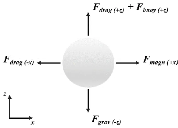
There are four relevant external forces acting on magnetic particles moving through a viscous medium: the hydrodynamic drag force (𝑭𝑑𝑟𝑎𝑔; 𝑥, 𝑦, 𝑧 components); the gravitational force (𝑭𝑔𝑟𝑎𝑣; −𝑧 component); the buoyant force (𝑭𝑏𝑢𝑜𝑦; +𝑧 component); the magnetic force (𝑭𝑚𝑎𝑔𝑛; 𝑥, 𝑦, 𝑧 components). Figure 20 shows a schematic diagram of the forces acting on a magnetic particle.
Figure 20. Diagram of the forces acting on a magnetic particle within a viscous medium. The y components (out of the plane) are not represented.
27 These forces are given by:
𝑭𝑑𝑟𝑎𝑔= 6𝜋𝜂𝑅𝑝(𝒗𝑝− 𝒗𝑓) (11)
𝑭𝑏𝑜𝑢𝑦= 𝜌𝑓𝑉𝑝𝒈 (12)
𝑭𝑔𝑟𝑎𝑣 = 𝜌𝑝𝑉𝑝𝒈 (13)
𝑭𝑚𝑎𝑔𝑛 = 𝑭𝑍= 2(𝒎 ∙ ∇)𝑩 (14)
In these equations, η is the viscosity of the fluid, 𝑅𝑝 is the average radius of the particle, 𝒗𝑝 and 𝒗𝑓 are the particle and fluid velocities, respectively; 𝜌𝑝 and 𝜌𝑓 are the particle and fluid densities, respectively; 𝒈 = −𝑔𝒌̂ is the acceleration of gravity.
In order to displace non-uniformly the magnetised particles along the bondline of the joint, it was decided to use permanent magnets, which can be arranged to produce a magnetic field of the required magnitude with favourable geometry and gradient.
The modelling of magnetophoresis of cork-magnetite microparticles for different magnet arrangements was made using the COMSOL Multiphysics software. This software has three important modules which can tackle different parts of a magnetophoresis model. The “Magnetic fields, no current” module is used to calculate the magnetic field distribution of a system of permanent magnets. Magnet geometry and dimensions, as well as corresponding magnetic properties, such as the remnant magnetisation and magnetic relative permeability, can be input. The “Creeping flow or laminar flow” module defines the type of fluid motion, the temperature and fluid’s (adhesive’s) properties, such as the density and dynamic viscosity. Finally, the “Particle tracing” module is used to simulate the motion of a set of magnetic particles within the adhesive fluid, driven by a static non-uniform magnetic field. Input parameters include the number of particles (not exceeding 1% of volumetric fraction for more accurate results), particle density, size and relative permeability; the time at which the particles are randomly released can also be specified. The forces acting on the particles are of the types described by Eq. (11-14).
A limitation of the “Particle tracing” module is that it does not allow the modelling of magnetic other than paramagnetic particles. The more complex magnetisation curve of ferrimagnetic cork-magnetite particles must, therefore, be approximated by a linear relationship typical of paramagnetic materials. A particle can be modelled by sketching a cork sphere and a shell of magnetite, but this is not a feasible solution since it would have to be replicated for more than 100 particles. In effect, for a typical adhesive layer of 25×50×0.5mm and particles with a diameter of 125-250μm, a 1% volumetric fraction of particles corresponds approximately to 1811 particles. Moreover, their initial positions would have to be handpicked and their magnetisation curves individually defined. Despite
![Figure 6. Schematic shear stress distribution at failure in mixed bi-adhesive joints [18]](https://thumb-eu.123doks.com/thumbv2/123dok_br/15709465.1068714/27.893.237.651.543.944/figure-schematic-shear-stress-distribution-failure-adhesive-joints.webp)
![Figure 7. Mixing ratio along the length of an adhesive joint (all dimensions in mm, adapted from [24])](https://thumb-eu.123doks.com/thumbv2/123dok_br/15709465.1068714/28.893.299.593.355.522/figure-mixing-ratio-length-adhesive-joint-dimensions-adapted.webp)
![Figure 8. Mechanical properties distribution along the overlap of a FGA joint obtained by graded cure [25]](https://thumb-eu.123doks.com/thumbv2/123dok_br/15709465.1068714/29.893.222.673.240.498/figure-mechanical-properties-distribution-overlap-joint-obtained-graded.webp)
![Figure 9. Mould with the coil system that allows the graded cure in SLJs (adapted from [28])](https://thumb-eu.123doks.com/thumbv2/123dok_br/15709465.1068714/30.893.274.624.107.406/figure-mould-coil-allows-graded-cure-sljs-adapted.webp)
![Figure 10. Cell structure of a cork (a) board and (b) particle (adapted from [31]).](https://thumb-eu.123doks.com/thumbv2/123dok_br/15709465.1068714/32.893.189.705.820.1025/figure-cell-structure-cork-board-b-particle-adapted.webp)