Implementation of a Stand-Alone Photovoltaic
Lighting System with MPPT Battery Charging and
LED Current Control
José António Barros Vieira1, Alexandre Manuel Mota2
1
Escola Superior de Tecnologia de Castelo Branco,
Departamento de Engenharia Electrotécnica, Av. Empresário, 6000 Castelo Branco, Portugal, Tel: +351 272 339300, Email: zevieira@ipcb.pt
2
Universidade de Aveiro, Departamento de Electrónica Telecomunicações e Informática, 3810 Aveiro, Portugal, Tel: +351 234 370383, Email: alex@ua.pt
Abstract — This paper presents a efficient stand-alone
battery photovoltaic (PV) lighting system which can provide functional illumination based on power light-emitting diodes (PLEDs). PLED with specific features of small size, long life and high-brightness light will be choices of future light sources. The PLEDs are feed using a lead acid battery that is charged with a PV panel.
This paper presents an interface board with a ATMEL ATTINY861V microcontroller, a single-ended primary inductance converter (SEPIC) and input and output voltage and current measurements. The microcontroller runs the perturbation and observation (P&O) maximum power point tracker (MPPT) algorithm used in battery charging process. This algorithm makes the system more efficient. In order to control the PLEDs current, an equal interface board is used running now the proportional integral (PI) current PLED control algorithm adjusting the wanted level of light in the PLEDs array. The two identical interfaces boards based in the economic microprocessor achieved very good results in battery charging and discharge supervision improving the efficiency a life-time of the lead acid batteries (first board) and presents good current control results in the PLEDs array (second equal board) providing a constant PLEDs light even in voltage battery variations or discharges. The stand alone lighting system monitors the surround area and if it feels any movement it changes the level of light of PLEDs from signal light to illumination light. After a pre-defined time it comes back to signal light, saving energy.
I. INTRODUCTION
Nowadays stand-alone photovoltaic lighting system has been generally used in rural areas and gradually used in city areas like public gardens lighting. Common street illuminations has big energy costs for the municipals and it is urgent to change to green light souses as photovoltaic panels with brightness power light-emitting diodes. Photovoltaic system is gaining increased importance as a renewable source due to advantages such as little maintenance and no noise and wear due to absence of moving parts. But there are still two principal barriers to the
use of photovoltaic systems: the high installation cost and the low energy conversion efficiency. To increase the ratio output power/cost of installation it is important that PV panel operates in maximum output power (MPP) to absorb the maximum power possible. The combination of PV panels with power LEDs makes the called new green light sources. Light-emitting diode has been widely investigated in lighting systems because it has many advantages: high luminous efficiency, low environment pollution, long life and firmness. LED lighting system supplied by batteries is one of effective solutions to home, vehicle and signalisation lighting system [1-5].
LED lighting system consists of three major parts: batteries, lighting controller, and LEDs module. Boost converter is usually used as main circuit of the controller [3], [4]. It is difficult to control LEDs light, due to its nonlinearity electrical characteristics and temperature sensitivity [3], [4]. Ref. [4] gives the disadvantages of constant voltage control and the necessity of constant current control. However, conventional simple constant current control strategy may cause over current and overheats of LEDs, because it ignores the temperature characteristics of LED. Moreover, the strategy might over discharge batteries and shorten their life due to neglecting the discharge process of batteries [4].
This work proposes an intelligent controller for power LED lighting systems and a photovoltaic battery charging system using a SEPIC and the ATMEL ATTINY861V microcontroller. It has the following advantages: (1) board with a SEPIC and input and output voltage and current measurements used by the ATTINY861V to control the battery charge and supervise discharge, (2) an equal board as the presented previously used to control the PLEDs current and brightness using a PI control algorithm. To have in account the temperature affects in the lead acid battery
charge process and in PLEDs, the temperature in both subsystems are read and affects theirs algorithm.
This paper is divided in eight sections, as follows: section I introduction, section II presents the construction and description of the all system, section III presents the solar array characteristics, and section IV shows the DC/DC converter. Section V presents the algorithm proposed to the different stages of the lead-acid battery charging process, section VI shows the power LED array, section VII presents the PI control algorithm ending with conclusions and future work presented in section VIII.
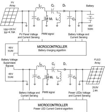
II. CONSTRUCTION AND DESCRIPTION OF THE ALL SYSTEM In Fig. 1 is presented the block diagram of the all system. The objective is to construct a stand-alone photovoltaic lighting intelligent system using power LEDs.
First, a photovoltaic panel of 100 Watt of power is used to provide the energy to charge a lead acid battery of 48 Volt and 50 Ah. These two blocks are connected with a board that has a DC/DC controlled by a microcontroller that runs the charge algorithm optimizing the transferred energy and also monitors the battery discharge. The lead acid battery is used to feed a power LED light. These two blocks are connected with a second equal DC/DC board that runs now the control current algorithm needed to control the power LED lighting system.
To avoid waste of energy, the system supervises movement around the system and it changes the LEDs current and its correspondent light.
The hardware of the DC/DC board was made to satisfy the two interfaces: a SEPIC because of its versatility and resistive sensors used to measure input and output voltage and current that will be used in both boards and one low power microcontroller ATTINY861V that will runs the two different algorithms (runs the charge algorithm and monitors the discharge or runs the control current algorithm needed to control the power LED lighting system).
The needed to control the current in the LEDs became from the voltage variations of the feed battery that will change during time, temperature and level of charge that could cause variations in the light level of the LED lighting system. The PV electrical characteristics are chosen based, especially, on the levels of energy needed to feed the system: battery and LED lighting system load. The project parameters are based in the following: generated energy during the day light should be bigger than the consumed energy in the night lighting; this way the battery will accumulate energy that could be used in shadow days where the generated energy is smaller. If the battery is 100% charged and there is no sun for two or three days the system still works normally using this accumulated energy.
There were used 45 power LEDs consuming 72 Watt of power to make the LED lighting system with the aim to provide a similar lighting of the given by a classical public lighting system.
III. SOLAR ARRAY CHARACTERISTICS
The maximum power point of a solar panel changes in accordance with changes in the solar irradiance and the respective panel temperature [6, 7].
The curve power versus voltage at a maximum level of solar irradiation of the used PV panel (120 Watt) is illustrated in Fig. 2.
The MPP of the panel is located at the knee of the power-voltage curve. According to the maximum power transfer theory, the power delivered to the load is maximum when the source internal impedance matches the load impedance [8].
Thus, the impedance seen from the converter input side (can be adjusted by PWM control signal) needs to match the internal impedance of the panel if the system is required to
P o w e r (W ) 0 20 40 60 80 100 120 0 5 10 15 20 25 30 35 40 U (V ) P o w e r (W )
Fig. 2. - P-V characteristics of a photovoltaic panel for a maximum level of solar irradiance S at a temperature of 27 ºC.
Fig. 1. – Stand-alone photovoltaic lighting block diagram. (PWM used to define the duty cycle)
operate at or near the MPP. If the system operates on the voltage source region (namely low impedance region) of panel characteristic curve, the panel terminal voltage will collapse [9].
It is known that the optimal point for the efficient use of the panel depends of the values of the panel temperature [6-9]. The main function of a MPPT is to adjust the panel output voltage to a value which the panel supplies the maximum energy to the load [8]. The applied MPPT algorithm will be explained in section V.
IV. DC/DCCONVERTER
To implement the MPPT algorithm it is used the SEPIC. This DC/DC converter is an increasingly popular topology, particularly in battery powered applications. As the input voltage can be higher or lower than the output voltage this converter presents obvious design advantages. In this work, for implementation of maximum power point tracker, a SEPIC working mainly in continuous conduction mode is used as the power-processing unit. Switch N channel MOSFET M1 with a frequency of 125 KHz the PWM signal with 10 bits of resolution will control the SEPIC. The power flow is controlled by adjusting the on/off duty ratio of the switch M1. Fig. 3 shows the schematic of the DC/DC converter implemented.
Using a PV panel with the following characteristics: maximum power Pmax=120 W, maximum voltage Vmpp=30 V, maximum current Impp=4 A, the DC/DC design starts with the selection of the two separate inductors L1 and L2. For a general working point with:
Input voltage (Vin = VTE) – 40.0V; Output (Vout & Iout) – 60V, 4A; Switching frequency (Fs) – 125 KHz; Expected efficiency - 90%
As it was projected in previous work made by the author [10], the SEPIC components used are: L1 = 280µH L2 = 280µH with Isat = 7.0A, C1 = 470 µF, C2 = 470µF, C3 = 470µF, M1 of Imax = 7.0A and a diode D1 of Imax 7.0A.
V. BATTERY CHARGE AND DISCHARGE ALGORITHMS The complete battery charging demands to the controller a complex control strategy, in which it would be possible to charge the battery, between its limits, in the faster possible way since working periods of energy generation of the PV panel are limited [14]. To achieve a fast, safe and complete battery lead-acid charging process, some of the
manufacturers recommend dividing the charging process in four stages that are designated by: (1º) trickle charge, (2º) bulk charge, (3º) over charge and (4º) float charge [11] and [12].
In this work there were made some simplifications in the implementation of the four different charging stages of a lead-acid battery. The 1º stage was not implemented because the discharge battery with this prototype board does not pass below VFLOAT (minimum lowest security voltage specified by the battery manufacturers). The applied load is disconnected from the battery by the control algorithm avoid reaching critical discharge. The value of VFLOAT depends or is a function of the battery temperature.
The 4º stage was not implemented but the 3º stage is continued until the charge current reach ISTEADY (near to zero current) and finally the charging process is ended. When the PV panel has energy to delivery and the battery voltage is below the VOC the control algorithm executes the 2º stage.
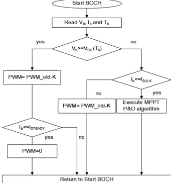
The battery charging implemented algorithm can be seen in Fig. 4. Where Vb and Ib are the battery voltage an delivered current and Tb is the battery temperature. The maximum value of the VOC depends of the battery temperature. From Fig. 6 it is clear that only the 2º and the 3º stages are implemented from the four stages proposed in [11] and [12].
In the 2º stage of the battery charge it is very important use of an MPPT algorithm to maximize the absorbed PV panel energy.
Fig. 3. - SEPIC DC/DC converter circuit.
Fig. 4. - Battery charging algorithm with two main stages (bulk and over charge BOCH) (PWM used to define the duty cycle).
The P&O is one of the so called ‘hill-climbing’ MPPT methods, which are based on the fact that in case of the V-P characteristic, on the left side of the hill of the MPP the variation of the power against voltage dP/dV > 0, while at the right, dP/dV <0 [13].
If the operating voltage of the PV panel is perturbed in a given direction and dP/dV > 0, it is known that the perturbation moved the panel's operating point toward the MPP. The P&O algorithm would then continue to perturb the PV panel voltage in the same direction. If dP/dV < 0, then the change in operating point moved the PV panel away from the MPP, and the P&O algorithm reverses the direction of the perturbation [15]. The main advantage of the P&O method is that it is easy to implement, and its low computational demand. However, it has some limitations, like oscillations around the MPP in steady state operation, slow response speed, and tracking in wrong way under rapidly changing in sum radiations [15][16][11]. To reduce the presented limitations it will be useful to use a small sampling rate. In this work it was used a sampling rate of 100 ms.
Using the SEPIC with current and voltage resistance sensors illustrated in Fig. 5, the P&O MPPT algorithm was implemented. The MPPT algorithm needs only the PV voltage and current information, and the battery voltage and current information to control the battery charging process.
Where R0=R5=0.005Ω and VR0 VR5 are the amplified voltages used to read input and output currents. R1=R3=910KΩ R2=R4=47KΩ are used to read input and output voltages.
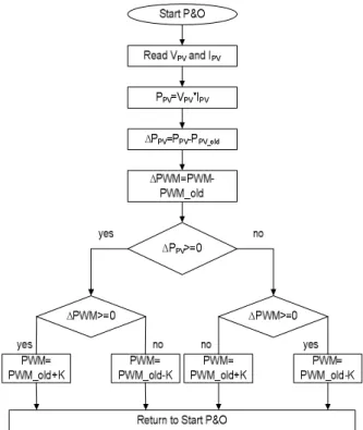
The flow chart of the P&O MPPT implemented algorithm is illustrated in Fig. 6.
The parameter K is the step given to the duty cycle of the PWM signal. This parameter can vary depending of the working point of the DC/DC converter, linear or non linear region.
The MPPT algorithm is executed in the microcontroller, which has ten 10-bits analogue-to-digital (A/D) converters and two fast PWM mode signals. The control circuit compares the PV panel output power before and after a change in the duty ratio of the DC/DC converter. It is expected that the MPP presents a constant oscillation inherent to the algorithm.
In the developed board is also used an algorithm to supervise the battery discharge because for long and good working periods of a lead acid battery its voltage can not goes below a certain value established by the manufacture. If the discharge goes deep several times the good working period of the battery will be smaller than the one achieved with out this deep discharges. It is used a P channel MOSFET to connect and disconnect the load (power LED lighting system) from the battery. The microcontroller supervises the battery voltage and when the lead acid voltage goes below a certain value which means that its level of discharge is big the battery is disconnected from the load by the microcontroller. After a period of charge running the previews MPPT algorithm the battery is connected again to the power LED lighting system that will start working as it was projected.
The implemented prototype board is illustrated in Fig. 7. It can be seen the PV panel input connection (I) in the right side of the board and, in the left side, the connection to the battery output connection (B) and the load output connection (L) that connects to another board like this having now the battery connected in the input (I) and the power LED array connected in the output (B). In the right button side are the NTC temperature sensors (green).
VI. POWER LEDARRAY
The power LEDs used to make the lighting system are white with 3.2 Volt and 500 mA each to give the maximum
Fig. 6. - P&O MPPT algorithm (PWM used to define the duty cycle applied in the MOSFET gate).
Fig. 5. - Voltage and current sensors for battery charging with MPPT algorithm (first board) or LED lighting current algorithm (second board).
brightness and light at low working temperatures (0 to 50ºC).
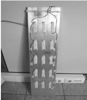
The number of PLEDs used to make the PLED lighting system is chosen with the aim to give a desired light. So, there were used 45 PLEDs, 5 frames in parallel of 9 PLEDs each connected in series as illustrated in Fig. 8 and 9. The PLED lighting system will consume about 72 Watt of power giving the maximum light. This system feels movement around the lighting system with a PIR sensor (persons or vehicles) giving the maximum lighting and brightness for 5 or 10 minutes (program parameter). If the system does not feel any movement around it the light level decreases to a minimum value consuming 18 Watt.
The minimum and maximum currents in the power LED lighting system are programmed in the manufacturing phase or it could be changed by external SPI programming. These values are saved in EEPROM positions that can be reprogrammed.
To reduce the brightness variations with temperature, the PLEDs need an efficient dissipation material behind them to avoid the overheating of the LEDs providing a good
temperature working point. In Fig. 8 it is illustrated the prototype of the 45 power LED lighting system with a big dissipation metal. The PLEDs are bought in OSRAM and integrated in a small PCB that will connect to our aluminium dissipater.
A lens will be also used to focus the LED light to the floor making a desired light area in the floor. The best lens used in the lighting system is still in a study phase.
VII.PICURRENT CONTROL ALGORITHM
To obtain a constant light it is important that the PLEDs temperature is low and the current is constant. When the light system is turn on the current control board uses a soft started because the DC/DC does not work correctly with big current transitions. When the real current (IPLED) is near to the desired current (IDPLED) the Proportional Integral (PI) controller starts working adjusting the PWM signal to reach the desired current forcing an error (EPLED) of zero.
Fig. 10 shows the block diagram of the PI controller where the gain parameters were adjust by testing and experimenting. The SEPIC is a non linear block that was projected to work in continues region for the desired currents.
With a sampling period of one millisecond the PI controller achieved good current control results even with battery voltage variation caused by charge and discharge periods, as can be seen in Fig. 11. Behind the current control, the microcontroller of this board also monitors the PIR sensor defining the desired applied current in the PLEDs array at each time. It also supervises the output Fig. 7. - Photo of the battery charger/lighting current control board.
Fig. 8. – PLED lighting system configuration.
Fig. 9. - Photo of PLED lighting prototype.
Fig. 10. – Block diagram of the PI controller (PWM used to define the duty cycle).
PLEDs voltage array to detect open LED frames, as can be seen in Fig. 11.
VIII. CONCLUSIONS AND FUTURE WORK
This system was developed to be modular or working as a PV battery charger or current control in power LEDs array using lead acid batteries or even connected in cascade with both functions. These modules could work until 120 Watt of power, maximum voltage 80 Volt and maximum current of 4.0 Ampere.
The results of the developed module working as a photovoltaic battery charger are presented in previous work made by the author [10]. It is clear that the used of MPP tracker algorithms in battery charging and the discharge monitoring present obviously benefits to the life duration of the lead acid battery. The absorbed power from the photovoltaic panel is improved in 30% to 50% comparing to direct connection depending level of adaptation of the PVs and batteries. The stand alone system with the MPPT delivers always more energy to the battery than a simple direct connection. Using this developed board to control the power LEDs current achieved very good results using a simple proportional and integration control algorithm. The battery voltage and the desired current don’t have fast changes so the integral square error (ISE) of the control system is near to zero.
These modules have power efficiency between 80% (worst case) to 92% (best case).
The proposed stand alone public park lighting system is cheaper than the traditional ones globally (observing installation and maintenance phases). The stand alone lighting system monitors the surround area and if its feel any movement (person) it changes the level of light of
PLEDs from signal light to illumination light. After a pre-defined time it comes back to signal light, saving energy.
As future work we need to study the PV panel performance along one normal year to see the real absorbed energy that depends of the weather but also of the characteristics of the PV panel. This study will be need to preview with some degree of precision the autonomy of the stand alone system with the PV panel and lead acid batteries.
REFERENCES
[1] M. O. Holcomb, R. Mueller-Mach, G. O. Mueller, D. Collins, R. M. Fletcher, D. A. Steigerwald, et al, “The LED light bulb: are we there yet? Progress and Challenges for Solid State Illumination,” in IEEE Conference on Lasers and Electro-Optics, Taipei, China, 2003. [2] K. Cheng, and K. W. E. Cheng, “General Study For Using Led to
Replace Traditional Lighting Devices,” in IEEE International Conference on Power Electronics Systems and Applications, Hong Kong, China, 2006, pp. 173-177.
[3] Yang Heng, Design Of Led Lighting Converter and Examples. Beijing: China Electrical Press, 2008.
[4] Bin Sheng, The Design of Serial/Parallel White Led Driver IC with Current-Regulated Based on Boost Converter, Master thesis, Jilin University Chang Chun, China, 2007.
[5] J. Zhang, S. Pei-shi, and L. Haitao, “Design Of Photovoltaic Charger of Led Street Lamp For Intelligent Zed Community,” Chinese Journal of Power Sources, vol. 31, no. 2, pp.157-159, 2007
[6] M. Riza, et al., “A Maximum Power Point Tracking for Photovoltaic-Spe System Using a Maximum Current Controller”, Solar Energy Materials & Solar Cells,vol.75 , pp 697–706, 2003.
[7] H. Knop, Analysis, Simulation, and Evaluation of Maximum Power Point Tracking (MPPT) Methods for a Solar Powered Vehicle, Mater of Science Thesis in Electrical and Computer Engineering, Portland State University, 1999.
[8] A. M. Torres, Aproveitamento Fotovoltaico Controlado por Redes Neurais Artificiais Interligado ao Sistema Elétrico, MSc Thesis, GPEC – DEE – UFC, Spt/98.
[9] C. Hua and J. Lin, “An On-Line MPPT Algorithm for Rapidly Changing Illuminations of Solar Arrays”, Renewable Energy, vol. 28, pp 1129–1142, 2003.
[10] J. Vieira., A. Mota, “Maximum Power Point Tracker Applied in Batteries Charging with PV Panels” IEEE International Symposium on Industrial Electronics, ISIE 2008, vol. 1, pp 202–206, July 2008. [11] K. Hesse, An Off-Line Lead -Acid Charger Based on the UC3909,
Technical report, Unitrod Company, 1997.
[12] R. H. Rosemback, Conversor CC-CC Bidirecional Buck-Boost atuando como Controlador de Carga de Baterias em um Sistema Fotovoltaico, Mater of Science Thesis in Electrical Engineering, University Federal de Juiz de Fora, 2004.
[13] D.P Hohm, M. E. Ropp, “Comparative Study of Maximum Power Point Tracking Algorithms Using an Experimental, Programmable, Maximum Power Point Tracking Test Bed”, Photovoltaic Specialists Conference, 2000. Conference Record of the Twenty-Eighth IEEE, pp 1699 – 1702, 15-22 Sept. 2000.
[14] N. Femia, G. Petrone, G. Spagnuolo and M. Vitelli: “Optimizing Sampling Rate of P&O MPPT Technique” Power Electronics Specialists Conference, PESC04, vol. 3, pp 1945-1949, 20-25 June 2004.
[15] A. Brambilla, M. Gambarara, A.Garutti and F. Ronchi: “New Approach to Photovoltaic Arrays Maximum Power Point Tracking”. Power Electronics Specialists Conference, PESC 99, vol. 2, pp 632– 637, July 1999.
[16] M. A. E. Galdino, C. M. Ribeiro, “A Intelligent Battery Charge Controller for Small Scale PV Panel”, 12th European Photovoltaic Solar Energy Conference and Exhibition, 1994.
Fi Fig. 11. – PI current control and PLEDs over voltage supervision algorithm (PWM used to define the duty cycle).