José António Barros Teixeira
A new Framework to enable rapid
innovation in Cloud Datacenter through a
SDN approach
Dissertação de Mestrado
Departamento de Informática
José António Barros Teixeira
A new Framework to enable rapid
innovation in Cloud Datacenter through a
SDN approach
Mestrado em Redes e Serviços de Comunicações
Trabalho realizado sob orientação de
Professor Stefano Giordano
Professor Alexandre Santos
I would like to thank my parents for standing up for the true meaning of the sentence which i naively wrote in gifts as a kid ”Para os melhores pais do mundo” (”For the best parents in the whole world”). A big thank you to my brother for his buddah patience while raising me and for teaching valuable lessons. To my godmother and godfather for their support and for the strategies which have always given me different perspectives on important subjects. All of you have been true companions along this life and mean the world to me.
To Fábio, for being able to put up with me for all these years. The greatest adventures I ever had were with you, you are a true friend.
A big thank you to professor Giordano and Adami for taking me into their research group, and guiding all my work. I would also like to thank Gianni for its indispensable guidance, he was a example of a tutor and an inspiring person. To everyone in the lab, it was one of best places where I’ve worked, and you were the ones that made that made it this way (thank you also for showing me the best food and places Italy has to offer).
A special thank you to professor Alexandre Santos for believing in my potential and for helping going further.
Finally, to everyone I met along my academic life, this years would be this exciting without you, thank you for enriching them.
In the last years, the widespread of Cloud computing as the main paradigm to deliver a large plethora of virtualized services significantly increased the complexity of Datacenters manage-ment and raised new performance issues for the intra-Datacenter network. Providing heteroge-neous services and satisfying users’ experience is really challenging for Cloud service providers, since system (IT resources) and network administration functions are definitely separated.
As the Software Defined Networking (SDN) approach seems to be a promising way to ad-dress innovation in Datacenters, the thesis presents a new framework that allows to develop and test new OpenFlow–based controllers for Cloud Datacenters. More specifically, the framework enhances both Mininet (a well–known SDN emulator) and POX (a Openflow controller writ-ten in python), with all the exwrit-tensions necessary to experiment novel control and management strategies of IT and network resources.
Further more, the framework was validated by implementing and testing well known policies. Hybrid allocation policies (considering both network and servers) were also implemented and scalability tests were performed.
This work was developed under the ERASMUS student mobility program, in the Telecom-munication Networks Research Group, Dept. of Information Engineering, University of Pisa, and resulted in the paper Datacenter in a box: test your SDN cloud-datacenter controller at homethat was accepted into EWSDN2013.
Nos últimos anos, a difusão da computação em nuvem como o principal paradigma para oferecer uma grande variedade de serviços virtualizados aumentou significativamente a com-plexidade da gestão de Datacenters e trouxe novos problemas de desempenho para a sua rede interna. A prestação de serviços heterogêneos e a satisfação dos utilizadores tornou-se um de-safio para os provedores de serviços em nuvem, uma vez que as funções de administração de rede e do sistema (recursos de TI) estão definitivamente separados.
Como o Software Defined Networking (SDN) aparenta ser um caminho promissor para tratar a inovação em Datacenters, a tese apresenta uma nova framework que permite desenvolver e testar novos controladores baseados em Openflow para Datacenters. Mais especificamente, a framework melhora o Mininet (um emulador SDN) e POX (um controlador OpenFlow escrito em python), com todas as extensões necessárias para o desenvolvimento de novas estratégias de TI e de gestão das redes de controlo.
Além disso, a framework foi validada através da implementação e teste de políticas conheci-das. Políticas híbridas de alocação de máquinas virtuais (considerando tanto os servidores como as redes) foram implementadas e testes de escalabilidade foram realizados.
Este trabalho foi desenvolvido no âmbito do programa de mobilidade de estudantes ERAS-MUS, no Grupo de Investigação em Redes de Telecomunicações TLCNETGRP, Departamento de Engenharia de Informação da Universidade de Pisa, do qual resultou a elaboração do ar-tigo Datacenter in a box: test your SDN cloud-datacenter controller at home que foi aceite no EWSDN2013.
Acknowledgments i
Abstract ii
Resumo iii
Contents iv
List of Acronyms viii
List of Figures viii
List of Tables x
1 Introduction 2
1.1 Introduction . . . 2 1.2 Motivation and objectives . . . 3 1.3 Thesis layout . . . 4
2 State of art 5
2.1 Available solutions . . . 5 2.1.1 CloudSim . . . 5 2.1.2 FPGA Emulation . . . 6
2.1.3 Meridian . . . 6
2.1.4 ICanCloud, GreenCloud and GroudSim . . . 7
2.1.5 Mininet . . . 8 2.2 Openflow Controllers . . . 9 2.2.1 NOX . . . 9 2.2.2 POX . . . 9 2.2.3 Beacon . . . 10 3 The Framework 11 3.1 Requirements . . . 11 3.2 Chosen technologies . . . 12 3.3 Framework architecture . . . 14 3.4 Directory structure . . . 16
3.5 Framework modules: Mininet Environment . . . 16
3.5.1 Topology Generator . . . 17
3.5.2 Traffic Generator . . . 17
3.5.3 Configuration file . . . 21
3.6 Framework modules: Controller . . . 23
3.6.1 Topology (Discovery Module) . . . 23
3.6.2 Rules (OF Rules Handler) . . . 24
3.6.3 Stats (Statistics Handler) . . . 25
3.6.4 VM Request Handler . . . 27
3.6.5 Network Traffic Requester . . . 28
3.6.6 VMM - Virtual Machines Manager . . . 29
3.6.7 User Defined Logic . . . 29
3.6.8 Other POX Modules Used . . . 30
3.7 Framework modules: Web Platform . . . 34
3.7.1 Features and usage . . . 34
3.7.2 Design . . . 37
3.8 Framework modules: VM Requester (VM Requests Generator) . . . 38
3.9 Using the framework . . . 39
3.9.1 Emulator . . . 39
3.9.2 Real Environment . . . 41
3.10 Framework extensions . . . 44
3.10.1 Enabling QoS . . . 44
3.10.2 Enabling Virtual Machine migration . . . 47
4 Validation and tests 52 4.1 Framework Validation . . . 52
4.2 Usecase: Hybrid VM Allocation policy . . . 55
4.3 Performance Evaluation . . . 57
5 Conclusions 61 5.1 Main contributions . . . 62
5.2 Future work . . . 62
A Mininet Environment – Configuration File 63
B Mininet - DC Topology Generator Algorithm 66
C Sniffex.c Modified 71
D clone_vms.sh 93
F Table creation script for MySQL database 98
G Script for enabling OpenVswitch on NICs 100
H Script for enabling NetFPGA 102
CPU Central Processing Unit DC Datacenter DCN Datacenter Networks IO InputOutput IP Internet Protocol IT Information Technology OF Openflow OS Operative System
QoS Quality of Service QoE Quality of Experience
RAM Random-access Memory
SDN Software Defined Networking VM Virtual Machine
VMM Virtual Machine Manager WAN Wide Area Network
2.1 Meridian SDN cloud networking platform architecture (Banikazemi et al. [1]) . . 7
2.2 POX vs NOX [2] . . . 10
3.1 Framework Architecture . . . 14
3.2 Tcpreplay performance in hybrid VM allocation policy - Switch utilization. Taken from [3] . . . 20
3.3 Print screen of Traffic Generator with Iperf . . . 21
3.4 Available port statistics . . . 25
3.5 Available flow statistics . . . 25
3.6 Edge switch link statistics exported ’.csv’ file . . . 27
3.7 WEB Platform - Top Panel . . . 34
3.8 WEB Platform - VM Request . . . 35
3.9 WEB Platform - VM list . . . 36
3.10 WEB Platform - VM Groups . . . 36
3.11 VM Requester console output . . . 38
3.12 Using the emulation environment. Top left: MN Topology Generator; Bottom left: VM Requests Generator; Right: Controller . . . 40
3.13 Architecture of the real environment . . . 41
3.14 Photo of the testing environment. Table: under the monitor - 2 servers; cube computer - aggregation and edge switches; laptop - DC gateway, controller and WEB Platform; Under the table: core switch . . . 43
3.15 QoS - Mininet testing environment . . . 46
3.16 QoS - Example of installed rules. Taken from [4] . . . 46
4.1 The environment . . . 53
4.2 WF vs BF . . . 54
4.3 Average Host link Ratio vs per Host Generated Traffic . . . 58
4.4 Average Host Link Ratio vs number of Hosts . . . 58
4.5 Average Host Link Ratio vs number of Hosts per Outside Host . . . 59
4.6 Host-PC Memory Utilization vs per Host Traffic Generated . . . 60
3.1 DC servers occupation example. (VMs allocated / server VM allocation capacity) 49 3.2 Keep DC policy algorithm - Best Fit vs Worst Fit . . . 51
Introduction
1.1
Introduction
A Cloud DC consists of virtualized resources that are dynamically allocated, in a seamless and automatic way, to a plethora of heterogeneous applications. In Cloud DCs, services are no more tightly bounded to physical servers, as occurred in traditional DCs, but are provided by Vir-tual Machines that can migrate from a physical server to another increasing both scalability and reliability. Software virtualization technologies allow a better usage of DC resources; DC man-agement, however, becomes much more difficult, due to the strict separation between systems (i.e., server, VMs and virtual switches) and network (i.e., physical switches) administration.
Moreover, new issues arise, such as isolation and connectivity of VMs. Services performance may suffer from the fragmentation of resources as well as the rigidity and the constraints imposed by the intra-DC network architecture (usually a multilayer 2-tier or 3-tier fat-tree composed of Edge, Aggregation and Core switches [5]). Therefore, Cloud service providers (e.g., [6]) ask for a next generation of intra-DC networks meeting the following features: 1) efficiency, i.e., high server utilization; 2) agility, i.e., fast network response to server/VMs provisioning; 3) scalability, i.e., consolidation and migration of VMs based on applications’ requirements; 4) simplicity, i.e., performing all those tasks easily [7].
In this scenario, a recent approach to programmable networks (i.e., Software-Defined Net-working) seems to be a promising way to satisfy DC network requirements [8]. Unlike the classic approach where network devices forward traffic according to the adjacent devices, SDN is a new
network paradigm that decouples routing decisions (control plane) from the traffic forwarding (data plane). This routing decisions are made by a programmable centralized intelligence called controller that helps make this architecture more dynamic, automated and manageable.
Following the SDN–based architecture the most deployed SDN protocol is OpenFlow [9] [10], and it is the open standard protocol to communicate and control OF-compliant network devices. Openflow allows a controller to install into OF–compliant network devices (called switches) forwarding rules which are defined by the administrator/network engineer and match specific traffic flows.
Since SDN allows to re-define and re-configure network functionalities, the basic idea is to introduce an SDN-cloud-DC controller that enables a more efficient, agile, scalable and simple use of both VMs and network resources. Nevertheless, before deploying the novel architectural solutions, huge test campaigns must be performed in experimental environments reproducing a real DC. To this aim, a novel framework is introduced that allows to develop and assess novel SDN-Cloud-DC controllers, and to compare the performance of control and management strate-gies jointly considering both IT and network resources [3].
1.2
Motivation and objectives
Although SDN came as a solution to fulfill the network requirements of the DCs, the only point of interaction with the IT resources is the generated traffic. By definition SDN does not go further, but if there could be a controller that manages both IT and network resources, all the information could be shared easily and both of them could greatly benefit: the network could start to anticipate IT actions and adapt itself to have higher performance, more redundancy, etc; the IT because the resources could be better managed so that the network, not only stops being the bottleneck, but actually helps the IT complete the tasks faster and without affecting adjacent resources.
When developing an Openflow controller, the administrator/network engineer goals are to implement the desired behaviour and to test it (making sure it suits the requirements). The cur-rently available controllers already provide some abstraction, which varies according to the type of programming language, but they are still too low level to allow rapid innovation. Following the implementation, tests campaigns must be performed and for it a controlled environment should
be set. Although Openflow allows the use of slices of the real network for testing purposes, it is more convenient to use an emulator since the DC size can be dynamic, different scenarios can be easily produced and it only needs a single computer – Mininet is such an emulator. Despite its flexible API, Mininet does not provide any type of traffic generator and is not DC–oriented: poor topology generation regarding DCs; no support for VMs;
A whole framework composed by a modified OF controller that allows the access to both IT and network resources through an easy-to-use but full featured API, and a testing environment that communicates with it to provide a real DC emulation is the the main objective. With this it is expected to endue the administrator/network engineer with all the tools needed to quickly develop, test and deploy VM and network management strategies into a DC.
1.3
Thesis layout
This thesis is structured into five chapters: the present Chapter 1 is a brief introduction of the proposed work, its motivation and objectives; the second is the state of art, it addresses the currently available solutions relating innovation in DCs and OF controllers; the third one fully describes the framework, its evolution, extensions and how it can be used; in the forth chapter is presented the framework validation, the results of a hybrid allocation algorithm and performance tests; and in the last chapter are made conclusions about the developed work, as well as suggestions for future work.
State of art
2.1
Available solutions
A number of research efforts have focused on novel solutions for emulation/simulation of Cloud DCs. The available solutions provide a reference and material to analyze and explore the concepts addressed along this thesis. This section presents and overview of them, highlighting their architecture, features and limitations.
2.1.1
CloudSim
Calheiros et al. [11] proposed a Java-based platform, called Cloudsim, that allows to estimate cloud servers performance using a workflow model to simulate applications behaviour. By pro-viding a framework for managing most key aspect of a Cloud infrastructure (DC hardware and software, VM placement algorithm, Applications for VM, Storage access, Bandwidth provision-ing) and by taking into consideration factors as energy-aware computational resources and costs, it helps to identify possible bottlenecks and improve overall efficiency.
Regarding the network aspect of Clousim, Garg et al. [12] extended such a system with both a new intra–DC network topology generator and a flow–based approach for collecting the value of network latency. However, in such a simulator, networks are considered only to introduce
delay, therefore it is not possible to calculate other parameters (e.g., Jitter). A SDN extension for Cloudsim as already been thought, Kumar et al. [13], but it still just an architecture design, meaning it has not been implemented yet.
Although it allows to predict how the management strategies will behave, as a simulator, it does not allow to run real applications and deploying the tested management logic in a real environment still requires everything to be developed.
2.1.2
FPGA Emulation
Ellithorpe et al. [14] proposed, a FPGA emulation platform that allows to emulate up-to 256 network nodes on a single chip.
”Our basic approach to emulation involves constructing a model of the target architecture by composing simplified hardware models of key datacenter building blocks, including switches, routers, links, and servers. Since models in our system are implemented in programmable hardware, designers have full control over emu-lated buffer sizes, line rates, topologies, and many other network properties.”
Ellithorpe et al. [14]
This platform also allows the emulation of full SPARC v8 ISA compatible processor, which along with full system control provides a greater system visibility. However, hardware program-ming skills might be a requirement and the cost of a single board is approximately 2, 000 dollars making this solution less attractive than ones based on just open–source software.
2.1.3
Meridian
Following the new shiny SDN paradigm, Banikazemi et al. [1] proposed Meridian, an SDN– based controller framework for cloud services in real environments.
As shown in figure 2.1, the architecture is divided into three main layers: Network abstrac-tions and API, where the network information can be accessed and manipulated (e.g. access con-trolling policies, prioritizing traffic); Network Orchestration, translates the command provided
Figure 2.1: Meridian SDN cloud networking platform architecture (Banikazemi et al. [1])
by the API into physical network commands and orchestrates them for more complex operations. it also reveals the network topology and its variations; finally the ”drivers” layer is an interface for underlying the network devices so several network devices and tools can be used.
Generally, this platform allows to create and manage different kind of logical network topolo-gies and use their information for providing a greater control of the DC. But as it works on top of a cloud Iaas platform (i.e., Openstack [15], IBM SmartCloud Provisioning [16]), it is limited to their management strategies and is only useful if one already has this type of infrastructure. Not having a testing environment is also a downside since the normal operation of the real DC can be compromised and also alter the testing results.
2.1.4
ICanCloud, GreenCloud and GroudSim
Other well–known open–source cloud simulators are ICancloud [17], GreenCloud [18] and GroudSim [19], but in none of them SDN features are available.
2.1.5
Mininet
”Mininet is a network emulator which creates a network of virtual hosts, switches, controllers, and links. Mininet hosts run standard Linux network software, and its switches support OpenFlow for highly flexible custom routing and Software-Defined Networking.”
Mininet [20]
As a network emulator for SDN systems, mininet can generate OF compliant networks that connect to real controllers without the need of hardware resources. Such features derives from the use of Open vSwitch and enables the assessment of the operation of an OF controller before its deployment in a real environment.
It also provides tools for automatically generating topologies, however, as they can be basic, an API is available to reproduce any type of topology and experiments. Mininet hosts behave just like real hosts, can run any program as long as it does not depend on non linux kernels, and can send packets through emulated interfaces. But as they share the same host file system and PID space, a special attention is required when killing/running programs.
Despite its flexibility, Mininet lacks of a complete set of tools that easily allow to emulate the behaviour of a cloud DC, thus raising the following questions:
∙ How to easily generate and configure typical DC topologies?
∙ How to simulate VMs allocation requests?
2.2
Openflow Controllers
In this section an overview of the most deployed and well-known controllers is presented.
2.2.1
NOX
NOX[21] was the first Openflow controller and was created jointly with the Openflow proto-col by a company named Nicira Networks. It is based in C++ programming language and made to provide fast and asynchronous IO. This controller supports Openflow 1.0 and give access to it through its API. It has a scalable approach for managing flows in multiple switches, which consists in sending only the first packet of a flow to the controller (when there are no rules that match the flow), so it can create a rule, and send it to the switches. After this all the packets belonging to that flow are forwarded according to that rule.
It already includes sample components like Topology Discovery, Learning Switch and Network-wide Switchto help the developers and researchers write code for programmatically controlling the switches.
2.2.2
POX
POX [2] is presented as ”NOX’s younger sibling”, and is a Python-based controller. With a similar structure as NOX, it supports the same GUI and visualization tools as NOX.
POX aims for the rapid development and prototyping of network control software and it also comes with sample components, but a bigger list of them (comparing to NOX).
Figure 2.2: POX vs NOX [2]
As can be seen in figure 2.2 where performance between NOX and POX is compared, NOX allows a smaller delay and handles more flows per second (possibility due to the programming language chosen), but POX taking into consideration that is written in Python, provides a good flow throughput (30000 flows per second) and delay (0.6ms per flow).
2.2.3
Beacon
Beacon[22] is a fast, cross-platform Openflow controller both event and thread–oriented. It is a Java-based controller making it easier to develop. It allows hot-swapping of code bundles (i.e replace the learning switch application without disconnecting the switches) and can be embedded in the Jetty enterprise web server and in a custom UI extensible framework.
Its development as started in 2010 and ”currently powers a 100-vswitch, 20-physical switch experimental data center and has run for months without downtime” [22] making it a stable controller.
The Framework
3.1
Requirements
Provide the user with a full package for the development and test of DC SDN Controller was one of the main purposes of the framework. Aiming for such goal, but without discarding the deployment in a real DC, a single software platform was designed and developed. Because the requirements change according to the controller being in the development or the deployment phase, so should the platform by creating and environment that best suits each of them.
Development & Testing Phase
Encourage a rapid development is one of the main requirements since it promotes innovation in the cloud DC. It must be simple and fast to develop the desired logic, which can be achieved by providing easy access to information and management of the network and servers. More specifically, automatic topology detection (and changes in it) associated with a high level API for accessing and managing switch’s and server’s information and statistics.
When testing, the framework should provide an automatic way of generating the VM re-quests and the traffic associated to each request (for testing the VM allocation and the network behaviour). The traffic generator should also correctly represent the DC traffic profiles. Allow-ing an easy access outside the controller for the statistics is also important, so it is possible to analyze the logic effects on the DC.
Deployment Phase
For the deployment, the framework should be easy to configure and monitor, and no extra effort should be made for the framework to run on the real DC (it should adapt automatically). There should also be an intuitive way to make manual VM requests, so clients can generate and manage their own VMs.
3.2
Chosen technologies
Openflow Controller: POX
Being POX a python derivative of the NOX controller, which was developed by the same peo-ple who developed the Openflow protocol, adopting it would be a surplus since there is a higher chance it will continue to support Openflow, and that the new versions/features are available as soon as possible. Besides, being a high level (comparing to C and C++), object and event ori-ented programming language, helps to create the abstraction level required for agile development and to make a more interactive controller.
Datacenter Emulator: Mininet
Mininet comes recommended in the Openflow tutorials as the platform for testing the OF compliant controllers. It also provides an API in python for the development of custom made topologies and specific experiments, which along with the capacity that the virtualized hosts have of running almost any program, makes it a powerful platform.
Virtualization platform: XCP 1.6 (Xen Cloud Platform)
As a free and opensource platform though for the cloud, XCP bring all the features belonging to Xen, plus it comes with ready-to-install images, making it simpler to install and configure. Having multiple interaction option is also an attractive feature, but having a Xen python API was
decisive since hit gives the possibility to write all the code in one programming language which helps keeping the platform consistent.
Note: although XCP was the virtualization technology adopted, support for others can be easily added.
3.3
Framework architecture
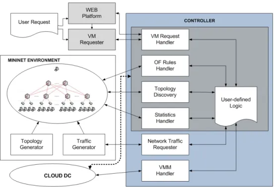
Figure 3.1: Framework Architecture
The framework architecture, shown in figure 3.1, gives an overview of the its modules and their interaction. The framework is divided into two main parts: the mininet environment - an extended version of mininet; and the controller - a modified, improved version of POX;
The mininet environment is made to be only used when testing the controller. It is composed by the mininet platform with two extra modules that explore its API. One of them is the Topology Generator, which allows to easily create multilayer 2-tier or 3-tier fat-tree DC topologies. The other one is the Traffic Generator that allows to correctly simulate the allocation of VM into each server by generating traffic from that server to the exterior of the DC. It also allows to simulate inter VM communication.
As for the controller, it automatically manages the modules in order to only use the ones that are needed for each phase (development and testing or deployment). Depending on it, the controller will interact with the mininet environment or the Cloud DC (i.e. the real Cloud DC infrastructure). In the figure 3.1, in the controller part, it can be seen a darker area which corre-sponds to the modules that are used in both phases. These modules are:
∙ VM Request Handler – Connects with the Web platform and/or the VM requester, and processes the VM requests;
∙ OF Rules Handler – Manages and keeps track of the installation/removal of the OF rules from the switches;
∙ Topology Discover – Manages all the information regarding the switches, links, servers and its detection;
∙ Statistics Handler – Collects statistics about the switches and links. Can be periodical or manual;
∙ User-defined Logic – Space for the administrator/network engineer to develop the desired DC management logic;
Regarding the other controller modules: the Network Traffic Requester which is only used when performing tests, tells the mininet environment how much, when, from where and where to, the traffic should be generated; and the VMM Handler which is only active when the controller is in a real environment, communicates with the hypervisor to perform all the operations regarding the VMs (allocate, deallocate, upgrade, etc).
Outside of the the mininet environment and the controller there is the WEB platform and the VM Requester, that were created for making VM requests. While the first one is a platform where DC clients can request (and manage) VMs that will be processed by the controller and later allocated by the hypervisor (oriented for the deployment phase), the VM Requester is an automatic full configurable VM request generator powered by random variables (oriented for the testing phase).
An important feature that was taken into consideration when designing the framework’s ar-chitecture is that all the modules are independent from each other, and they can be changed, removed or added in order to fulfill all the user requirements.
3.4
Directory structure
POX defined an ext folder so controller extensions could be added without interfering with their development. This folder is used by the framework to store most of the modules (including the ones that are not used by the controller). The framework directory is structured as follows:
∙ INIHandler – used only to read and write configuration files
∙ Rules – contains OF Rules Handler
∙ Stats – contains Statistics Handler
∙ Structures – used to stored basic class structures and event (Switch, Host, etc)
∙ Tools – external tools used in the framework (e.g. Dijkstra algorithm for calculating inter VM path)
∙ Topology – contains Topology Discover
∙ VM – Contains all VM related modules. User-defined logic (VM Allocation Manager) and VM Request Handler (VM Request Manager) are implemented here.
∙ XenCommunicator – VMM Handler (for now only supporting XEN hypervisor)
∙ Topology Generator (MN) – contains Mininet Topology and traffic generator
∙ VM Requests Generator – contains the VM requester
3.5
Framework modules: Mininet Environment
The Mininet Environment is composed by both mininet and two custom modules named Topology Generator and Traffic Generator. These two modules where added to fill the missing support for traffic generation and the basic integrated topology generator.
3.5.1
Topology Generator
Mininet allows their topology generator to create tree topologies but they do not have a Gateway, meaning that they cannot correctly emulate a DC since when traffic reaches the core switches it has nowhere to go (if it is traffic that addresses the outside of the DC).
Using its API, an algorithm for generating custom DC tree and fat tree topologies was created. The algorithm works by creating the gateways (as hosts on mininet) and core switches, and iterating through each gateway assigning the correspondent link and their characteristics to the core switches. Similarly, the same logic is used between the core and aggregation switches, followed by the aggregation and edge switches, and lastly with the edge switches and the servers (created as hosts on mininet). Details on the algorithm can be seen on appendix B.
It is able to generate any number of gateways, hosts and core, aggregation and edge switches. Is also generates the links between them, and the number of links between different levels (e.g. from the gateways to the core switches) can be chosen. This way it is possible to create fat tree topologies. Link bandwidth is also configurable by level, meaning one needs only to setup the bandwidth for the 4 network levels.
3.5.2
Traffic Generator
Since emulating traffic sources is a key point, reproducing both VM-to-VM and VM to out-of-DC data exchange is necessary to create an environment as close as possible to real scenarios. As mininet does not give any support to traffic generation, it is up to the user to do it. Since generating traffic manually for each VM allocation would be impractical for testing the DC policies, an automatic traffic generator was created.
For the mininet environment to know the traffic characteristics it should start generating for each VM, a network socket was open for communication with the controller. In this socket the following information is exchanged,
∙ Server where traffic should be sent from;
∙ Traffic characteristics (bandwidth, etc);
∙ Optional custom information (for supporting other features);
TCPReplay
With the goal of reproducing as closely as possible a DC behaviour, traffic samples from a real cluster were collected, and tcpreplay [23] was used to replay them. The sample was collected from the clusters of the Department of Informatics - University of Minho and has approximately 500Mb size.
As the sample traffic had to be adapted to suit the server interface’s IP, the sniffex.c [24] program (given as an example of pcap library usage) was modified.
For modifying traffic samples instead of live capturing the packets, offline capture mode must be set and then the pcap_loop can be started. Pcap_loop iterates throw each packet and applies the function passed as argument, in this case pcap_spoof_ip.
/* setup offline capture */
handle = pcap_open_offline(filename, errbuf); ...
/* now we can set our callback function */
pcap_loop(handle, -1, pcap_spoof_ip, NULL); pcap_close(handle);
Because part of the traffic sample captured contained VLAN tags, an if statement add to be added for pushing the pointer 4 bytes further (4 bytes is the VLAN tag size). After knowing where the ip header was, it was changed to the desired one, recalculated the checksum1, and dumped the new packet into a different file.
/* Remake IP Addresses on the copied packet */
if(ether_type == 0x0800)
ip = (struct sniff_ip*)(packet_cpy+SIZE_ETHERNET); else if(ether_type == 0x8100)
ip = (struct sniff_ip*)(packet_cpy+SIZE_ETHERNET+4); ...
/*Change IP addresses*/ inet_aton(ipSourceAddressString, new_s); ip->ip_src = *new_s; inet_aton(ipDestAddressString, new_d); ip->ip_dst = *new_d; ... /* Recalculate Checksum */ ip->ip_sum=0; uint16_t new_cksm = 0; if(ether_type == 0x0800) new_cksm=do_cksum(reinterpret_cast<uint16_t*>(packet_cpy+SIZE_ETHERNET), sizeof(struct sniff_ip)); else if(ether_type == 0x8100) new_cksm=do_cksum(reinterpret_cast<uint16_t*>(packet_cpy+SIZE_ETHERNET+4), sizeof(struct sniff_ip)); ip->ip_sum=htons(new_cksm); ...
/* Dump the packet */
pcap_dump((u_char*)file,pkt_hdr,packet_cpy);
When received a new VM allocation from the controller, the traffic generator started rewriting the traffic sample to fit the VM characteristics, and when ready, the modified sample was replayed from the server which was selected for the allocation. In order to generate traffic only during the time which the VM was allocated, the timeout program was used.
"./sniffex -f TrafficSample/traffic -s source_ip -d dest_ip"
Has the modification of the traffic sample was taking to long, compromising the testing ca-pabilities of the framework, the modified samples started to be generated when mininet was started (since the IP addressing scheme was already known). This allowed for much agile testing since when a VM allocation arrived, the only thing needed to be done was replaying the already generated traffic sample with the required characteristics.
The traffic generator was tested with a hybrid VM allocation policies. Unfortunately, due to the TCPreplay’ poor performance it was not possible to achieve the expected switch and link utilization. Trying to understand the problem, it was realized that TCPreplay uses a large amount
of CPU independently of the bandwidth which it generates. As an instance of TCPreplay was running for each VM, there was not enough processing power for all of them to run normally. As can be seen in figure 3.2, the switch utilization went little above the 2%. Despite the low switch/link utilization, it was still possible to see the implemented hybrid VM allocation working.
Figure 3.2: Tcpreplay performance in hybrid VM allocation policy - Switch utilization. Taken from [3]
Iperf
As an alternative to TCPreplay, Iperf [25] is a network diagnosing tool which is able to reproduce both TCP and UDP traffic. Although it does not allow to replay traffic samples, it is a good tool for testing the DC behaviour at its peak utilization. Spending few CPU is also an advantage since many instances of it are required to run at the same time.
Because it uses the server/client paradigm it had run both on the servers and on the gateways in order to work properly. In order to do so and coordinated with the controller VM allocations, the same method as before was used, but instead of running TCPreplay with the traffic sample, two instances of iperf were ran (both bidirectional, one with TCP and other with UDP). For allowing some flexibility, the balance of TCP against UDP traffic per VM can be changed. In figure 3.3 can be seen the output of the Traffic Generator, where Iperf is used and the generated
traffic is half TCP and half UDP.
Figure 3.3: Print screen of Traffic Generator with Iperf
D-ITG
Traffic emulation must be fully customizable (which iperf is not) in order to allow the user’s experiments: while traffic modeling is out of the scope of this framework, giving the user tools that allows to easily create different traffic profiles is a main issue. For this reason it is planned to integrate D-ITG [26], a distributed traffic generator that allows to generate a large spectrum of network traffic profiles(e.g., poisson distribution, DNS, VoIP, etc..). Application-specific traffic profiles can be defined, inserting their statistical parameters, possibly in the configuration file (i.e., traffic shape, transport protocol, transmission rate, traffic duration, etc..). Moreover, during the configuration phase, the user should be able to specify how frequently these applications run into the DC.
Similarly to what was happening before, every time a new VM is successfully allocated (i.e., the OF controller chooses the server to allocate the VM and sets up the rules on the OF switches) at least a new bidirectional traffic instance starts between one outside host and the one that hosts the new VM. It is worth pointing out that the number of instances and the type of traffic should only strictly depend on the application chosen in the configuration phase.
3.5.3
Configuration file
The configuration file for the Mininet environment includes parameters for both the Topology Generator and Traffic generator. It follows the normal structure of the .ini files, and all the configurations explained above can be made here. For organization purposes it is divided into types of configuration. An example of a configuration file can be seen in appendix A.
∙ TopologySwitches – for changing the number of switches of each type;
∙ TopologyHosts – for changing the number of hosts (servers or gateways);
∙ TopologyLinks – for changing the number of links between DC network level;
∙ SwitchBandwidth – for changing the link bandwidth of each DC network level;
∙ Traffic – for changing Iperf settings (UDP VS TCP ratio, etc);
3.6
Framework modules: Controller
The controller is the most important part of the framework, since all the interaction with the network and the IT resources are made through it.
3.6.1
Topology (Discovery Module)
The Topology is where all the information regarding the switches, links and it resources is kept and managed. It uses basic classes implemented under the structures directory and saves the information in the form of dictionaries for easy and fast access to it.
It also automatically detects the topology, and topology changes. To do so, it listens to the POX core events and uses two POX modules, the discovery and the host_tracker. For basic information about the OF switches it handles the ConnectionUp, ConnectionDown, SwitchJoin, SwitchTimeout and PortStatus events. The first four give information about the switch state, id (known as dpid) and connection (so rules can be installed), while the last one gives information about all their ports and their ports state (down, up, administratively down).
Regarding the discovery module, it raises an event related to the links (allowing to know if they exist, are up or are down). To do it, it uses LLDP (Link Layer Discovery Protocol) packets which are sent through the switches interfaces, and with this information, it raises a LinkEvent saying if a link is up or down, and which switches and ports it connects.
As for the host_tracker it allows to detect non OF devices(servers and gateways). The process for discovering them is similar to the one used by the discovery module, but it uses ping instead. Because this module does not raise any events, it was slightly modified to do so. 3 type of events where added HostJoin, HostTimeout and HostMove. Like the name suggests, HostJoin is raised when a host is detected and provides information to which switch and port it is connected; HostTimeout is raised when a host previously detected stop answering the ping request; and HostMove is raised when the host is connected to a different switch or port than the one registered before.
For classifying the level which the switches belong to (edge, aggregation or core), gateways need to be distinguished from the servers, otherwise all the directly connected switches will be
recognized as edge. As the addressing schemes are typically different from inside DC to the out-side, this was used to differentiate them. To be fully parameterizable, the IP addresses/network addresses of both can be configured in the provided configuration file.
Unfortunately, OF does not provide yet information about the ports bandwidth, so it has to be configured manually.
3.6.2
Rules (OF Rules Handler)
The Rules module provides methods for easily installing and deleting rules from the OF switches, and keeps track of everything that was installed. Once again the information is saved into dictionaries and both rules for outside DC communication and inter VM communication are stored. All the rules are defined by the user in the user-defined logic, but this modules provides easier methods for installing them (based only on destination and source IP). As more complex rules with special matching condition might be used, more complete methods are also available, giving the user higher control over the traffic.
For future work it is expected to implement supernetting with the goal of decreasing the amount of rules that are installed in each switch, which will have a direct impact on the rule searching time.
3.6.3
Stats (Statistics Handler)
Statistics
The statistics module allows for statistics to be collected and saved. Aiming to provide easier access to the statistics provided by OF, this module was developed. having access previous data collected is an important feature since it might be crucial to understand the DC behaviour.
OF by default provides statistics regarding the ports of a switch and the installed flows. In figures 3.4 and 3.5 a list of the available values is shown.
Figure 3.4: Available port statistics Figure 3.5: Available flow statistics
Although a lot of port statistical values are available, bitrate is not one of them. Without bitrate it is not possible to know the port usage ratio and as a consequence the switch usage ratio. As this is a threat if one wants to develop an algorithm considering the network (e.g. If network is considered for VM allocation, it makes no sense to allocate a VM in a server which is only connected to a overloaded switch).
Despite bitrate not being directly available, there are at least 2 ways to obtain it. One would be to change the OF switch implementation and protocol to implement it, but it is excessively intrusive and would turn the framework into a non standard option. The other one would be to use the byte count (in and out) and a time counter. Although it is not an accurate solution, it is the most viable.
Respecting the statistics, POX implementation of the OF controller uses events for notifying that the statistics request is ready. To obtain the bitrate as accurate as possible, a statistics request is made, the timestamp of the event with the statistical data is registered, a new request is made, and again the timestamp of the latest event is registered. By subtracting the oldest timestamp to the newest it is obtained the time between the statistical data. The amount of bytes that were counted in that interval can be obtained in the same way. Finally by converting the bytes into bits (multiplying by 8) and divide it by the time (converted to seconds), the bitrate is obtained.
#obtain the bit_rate for this port in mbps
bit_rate = ((bytes_count*8)/(time_elapsed))/1000000
To calculate the port ratio the bitrate is divided by the port capacity. For the switch ratio, an average of all its ports ratios is made.
Despite methods for accessing the statistics as they were collected is available, an alternative method is provided, which does a ponderation of the latest collected values with the average of the historical ones. The historical ponderation value can be changed in the configuration file.
bit_rate_port_stats[port_no] =
(self.historical_ponderation * temp_hist_bit_rate) + ((1-self.historical_ponderation)* newest_bit_rate)
Statistics can be collected, periodically (with periodicity indicated in the configuration file), can be retrieved whenever requested (e.g. a VM request arrives) or both.
Statistics Exporter
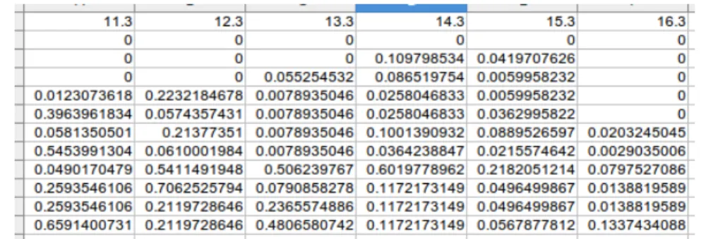
Statistics Exporterwas created with the purpose of allowing statistics to be analyzed outside the running environment. To do so, it periodically checks the statistics module, collecting and saving all the information into ’.csv’ files. Statistics exporter should have the same periodicity for statistics collection than the statistics module, in order to maximize the information gathered. Two types of files are generated: for switches and for links.
Figure 3.6: Edge switch link statistics exported ’.csv’ file
A link statistics file can be seen in figure 3.6. Columns represent the switch and its port, and lines the link ratio in each timestamp. Where the files are saved can be chosen in the configuration file.
3.6.4
VM Request Handler
This module is responsible for parsing the VM requests (allocation or inter VM commu-nication) and raising events with their requirements. It creates a thread and a socket inside it for receiving and parsing the VM requests from both the VM Request Generator and the WEB Platform. After the VM requests have been validated, an event with the VM requirements is raised.
For the VM allocation request the following event is raised,
class VMRequest (Event) : ’’’
Event with new virtual machine allocation request ’’’
def __init__ (self, vm_id, time, cpu, ram, disk, network, request_type, timeout) : Event.__init__(self)
self.vm_id = vm_id self.time = time self.cpu = cpu self.ram = ram
self.disk = disk
self.network = network
self.request_type = request_type self.timeout = timeout
Since inter VM communication is frequent in the DCs, allowing their communication without the need for the traffic to go to the gateway is important. For this reason, and because it is relevant that it is the administrator/network engineer defining the path, and event with the list of VMs to allow intercommunication is raised.
class InterVMComRequest (Event): """
Event with the inter virtual machine communication request """
def __init__(self, inter_vm_id, vm_list): Event.__init__(self)
self.inter_vm_id = inter_vm_id self.vm_list = vm_list
After the VMRequest or the InterVMComRequest have been processed and either allocat-ed/accepted or rejected (typically in the User-defined logic), this module communicates the state back to the source of the request.
3.6.5
Network Traffic Requester
The Network Traffic Requester only function is to capture the event which says the VM as been allocated, and notify the mininet module Traffic Generator to start generating traffic from the server in which the VM as been chosen to be allocated, with the network required characteristics and during the time the VM remains allocated
The network requirement varies according to the traffic generator being used, but in the case of Iperf, just the amount of bandwidth is requested.
3.6.6
VMM - Virtual Machines Manager
This modules provides an abstraction level for the communication with the hypervisor. How-ever, there are a lot of configurations that must be made before it can be used. These configura-tions vary from hypervisor to hypervisor, but in the case of XEN are the installation of XCP in each server, and the configuration of a VM template.
For the allocation process to be agile, a debian VM (other OSs are also supported) was previously installed and configured for external access. The idea is to clone this VM template, reducing the allocation time drastically.
By using XEN API, this process should not be hard to implement, however, what seemed like a simple implementation, rapidly became a ”nightmare” since the available documentation is very poor, and there is a lack of examples. With the impossibility of correctly interacting with Xen API, a different approach was taken. By using ssh to control the machine where the hypervi-sor was installed, the xe commands and a script created by citrix for cloning VM templates (can be seen in appendix D), a new VM was successfully allocated into a server. When the VM gets allocated, it is automatically started up, and an IP addressed is given (this IP address which is later communicated to the source of the VM Request, so the VM can be accessed).
3.6.7
User Defined Logic
While all the other modules provide methods or data structures that ease the process of ac-cessing and manipulating the information, this module just has to use those tools to produce the desired logic. The User Define Logic is a space for the administrators/network engineers to define their DC management policy (e.g.VM allocation policies, smart DC routing, etc). No limitations in terms of management functionalities are present. As long as everything is OF compliant and can be accessed through some provided API, it can be used in the logic.
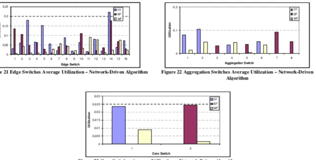
Aiming to help the administrator/network engineer understanding in which ways it could be used, an hybrid VM allocation policy is included (takes into consideration the switches statistics and the server occupation), and also the Dijkstra algorithm is applied for calculating the shortest path between VMs that wish to communicate directly.
The hybrid VM allocation policy is fully described in [3]. It includes 2 algorithms for VM allocation: a server driven; and a network driven.
” a) Server-Driven algorithm
In the Server-Driven algorithm, first a physical server is selected for placing the VM, then a sequence of switches is chosen for forwarding the traffic flows to/from that VM across the DC network(...)
b) Network-Driven algorithm
In case of the Network-Driven algorithm, when a new VM placement request arrives, candidate core, aggregation and edge switches are firstly selected using a specific selection policy (e.g., FF, BF or WF) and checking that switches are able to process and forward the overall traffic possibly exchanged by the VM (i.e., the switches are not overloaded and at least one downlink is not congested) (...) Next, the physical server is selected within the set of servers directly connected to the candidate edge switch by applying a VM placement policy (e.g., FF, BF or WF) and checking that its network link is not congested (...) The VM placement process ends when the OF Controller inserts the proper forwarding rule in the edge, aggregation and core switches.”
Adami, D. et al. [3]
With respect to the inter VM communication, an already implemented Dijkstra algorithm for shortest path was adopted (appendix E). As the data structure for the topology (graph) was different, it had to be converted before calling the shortestpath method. This method was used to calculate the shortest path between all combination of VM pairs.
The code for both implementations can be seen in2.
3.6.8
Other POX Modules Used
Besides using two POX modules on the topology module (Discovery and host_tracker), an-other module was also used: dhcpd. It is a simple DHCP server, which in the framework is used
2https://github.com/jbteixeir/Openflow-DC-Framework/blob/master/ext/VM/vm_
allocation_manager.py. For allocation algorithms please check the methods networkDrivenAlgorithm and serverDrivenAlgorithm, and for inter VM communication interVMPathAlgorithm
for attributing IP addresses for the newly created VMs. For simplicity, all the parameters can be configured in the controllers configuration file.
3.6.9
Configuration File
The configuration file on the controller makes it easier to configure parameters that can easily change. As one might prefer to insert the values in an interactive way, in case the configuration file does not exist, there is the possibility that each modules asks for the configuration it needs, and in the end everything is written into a file.
[topology] # link capacities in mbps outside_link = 60 core_link = 60 agg_link = 30 edge_link = 10 [host] #HOst Capacity
# cpu - number of cores # Ram and Disk - GB
cpu = 8 ram = 16 disk = 2000
[hostippool]
#dhcpip - ip of the dhcp server
server=10.0.0.0/16 gateway=10.128.0.0/16 dhcpip=10.0.0.254 vm=10.128.128.0/24 dns=8.8.8.8 [stats]
# polling time - seconds #Historial statistics weight
polling_time = 100 hist_weight = 0.125
[statsexport]
#directory where the switch and link statistics will be placed
switchsratiodir = ./stats linksratiodir = ./stats
Listing 3.1: Configuration file - controller (1/2)
[vmallocation] # algorithms - ND/SD #ND - Network Driven #SD - Server Driven algorithm = ND # policies - FF/BF/WF core_policy = BF agg_policy = BF edge_policy = BF host_policy = BF
#maximum ratio a switch can have so it is chosen for new vm allocation
#maximum ratio a link can have so it is chosen for new vm
allocation
switch_ratio = 1.20 link_ratio = 1.20
[vmreceiver]
#IP and port for listening to the VM requests
ip = 10.0.2.15 port = 3000
[credencial]
#Credential for xen hosts
username = root password = xensource
In the example above (listings 3.1 and 3.2), the configuration file includes sections for the main framework modules, but as can be seen, a section for the VM allocation as been added, where it can be chosen which algorithms will be used, and even the maximum ratio for switches and links to still be considered when choosing the path.
Adding parameters is as simple as inserting them in the configuration file, and, in the module where they are used, assign them to variables.
3.7
Framework modules: Web Platform
The WEB Platform was created to provide the DC clients with a platform where their VM requests could be made and their VMs could be managed.
3.7.1
Features and usage
Although it still is an early development phase, the included features are:
∙ Authentication system for clients;
∙ Request and View VMs;
∙ Request and View VMs Groups (for inter VM communication);
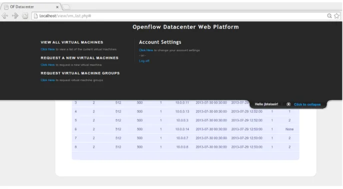
Figure 3.7: WEB Platform - Top Panel
The top panel of the WEB Platform is where the client can access all the available features, including to sign up or log in. It can be seen in figure 3.7.
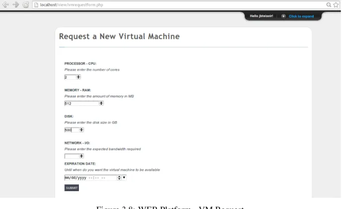
Figure 3.8: WEB Platform - VM Request
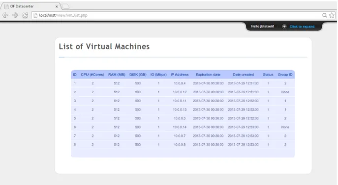
For requesting a VM the client needs to click in ”Request a new virtual machine”, fill the VM requirement fields and submit the request (figure 3.8). This request is sent to the controller, that after running the implemented allocation policy will install the rules and order the hypervisor to start the allocation process. When all these tasks are completed, the WEB Platform is informed of the success state of the operation, and information for the VM to be accessed is returned. If the client wants to view the VMs that it requested and their characteristics and current state, they are made available in ”View all virtual machines” on the top panel (3.9).
For requesting inter VM communication, a place for VM groups was created. The VM group page as similar looks to the VM list page, but with checkboxes for choosing the VMs that belong to the same group (figure 3.10). After requesting a VM group, a similar process to the VM allocation request is started. Instead of running the allocation policy, the VM group policy is ran, the rules are installed and the feedback about the process is given back to the WEB Platform.
Figure 3.9: WEB Platform - VM list
3.7.2
Design
The architecture of the WEB Platform follows the MVC (Model-view-controller) model. It includes a MySql [27] database to save information that is important for the WEB Platform normal functioning. For now, most of the information is just a copy of the one kept by the OF controller. Security concerns are beyond this decision. The database contains 3 tables: ”users” for keeping personal information about the users; ”vms” for information related to the VMs (e.g CPU, RAM, etc); and ”vm_groups” for mapping the VMs into the group they belong. A script for creating this configuration can be seen in appendix F.
For communicating with the OF controller a socket is opened and the requests are sent. For now they are string based requests, but it is planned to use an encrypted json [28] notation.
3.8
Framework modules: VM Requester (VM Requests
Gen-erator)
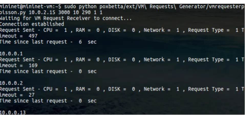
Figure 3.11: VM Requester console output
As explained before, this modules is only to be used when testing. Its purpose is to automat-ically generate VM requests. In order to do so, it uses a poisson random variable, for generating both the time interval between requests and the each of the requirements of the VM requests (CPU, RAM, DISK and Network).
Also developed in python, this independent program communicates with the controller VM request managerto send VM requests. It implements threads for receiving the status of the VM request, so it can at the same time keep making VM requests. The status are printed as the VMs get allocated.
3.9
Using the framework
3.9.1
Emulator
Setting up the development environment
The mininet website provides a Ubuntu 12.04 LTS virtual machine image with mininet (and all its dependencies) already installed and configured. By using this image in e.g Virtualbox [29] there is no need to change the native OS. If additionally ssh and ftp access to the Mininet VM are given, the administrator/network engineer can use its favorite text editor or IDE to change the code and test it. For adding the framework to the Mininet VM, one just needs to copy the framework folder inside the VM.
Testing new DC allocation policies
The controller part of framework can be ran like a normal POX module. Its name is ercs, and its responsible for calling all the sub-modules inside the controller. When testing, the DEBUG log level should be activated, as it prints more information into the console.
~/poxbetta/pox.py ercs log.level --DEBUG
For generating the desired topology, the configuration file provided under the same folder as the Mininet script must be changed, and script must be ran.
~/poxbetta/ext/Topology\ Generator\ \(MN\)/tpgeneratormn2.0.py
Finally, the VM requests are generated by running the following command,
python ~/poxbetta/ext/VM\ Requests\ Generator/vmrequesterpoisson.py {args}
The list of arguments comprises the controller socket IP and port, the VM request rate and the VM requirements.
In figure 3.12 is a print-screen of all the components running.
Figure 3.12: Using the emulation environment. Top left: MN Topology Generator; Bottom left: VM Requests Generator; Right: Controller
3.9.2
Real Environment
Setting up the real environment
The real environment was assembled using real PCs for both the servers and the switches. For the servers XCP 1.6 was used has the virtualization platform, and for the OF switches Open VSwitch - OF 1.0 complaint, except for the ones that had NetFPGA cards3.
The implemented architecture is shown in figure 3.13.
Figure 3.13: Architecture of the real environment
Since OF separates the data plane from the control plane, two separate networks are required. Thus, a non OF switch was added connecting the controller with all the OF switches an the servers. For simplicity reasons, the laptop in the figure3.13, is simultaneously the gateway, the OF controller and the WEB Platform.
The specifications of the equipment used is shown below.
∙ 2 x Servers
– Intel Xeon CPU [email protected] – 4 GB Ram
– 900 GB HD
– NIC Intel 82566DM-2 Gigabit Network Connection
3The NetFPGA is an open source hardware and software platform that is able to act as an OF 1.0 compliant
– NIC Intel 82541GI Gigabit Network Connection
∙ 2 x Edge Switches and 2 x Aggregation Switches
– AMD Phenom 9650 Quad-Core 1.16Ghz – 450 GB HD
– 4 GiB RAM
– 2 x NIC Intel 82571EB Gigabit Ethernet Controller
– NIC Realtek Semiconductor RTL8111/8168B Pci Express Gigabit Ethernet Con-troller
∙ 1 x Core Switch
– Intel Core i7 CPU 860 2.8Ghz x 8 – 4 GiB Ram
– 450 GB HD
– NIC Realtek Semiconductor RTL8111/8168B Pci Express Gigabit Ethernet Con-troller
– NetFPGA 4 ports Gigabit Ethernet
∙ 1 x Laptop (Gateway/Controller/WEB Platform)
– 1 Intel Core i5 2430M - 2.4Ghz x 4 – 8 GB RAM
– 500 GB HD
– 1 NIC Qualcomm Atheros AR8151 v2.0 Gigabit Ethernet – 1 NIC Intel Corporation Centrino Wireless-N 100
– 1 NIC ASIX AX88772A USB 2.0 Fast Ethernet Network Adapter
For enabling OF on the network interfaces of the non NetFPGA cards, a script was used. Although this configuration changes according to the network interfaces and their quantity, an example of the script can be found in appendix G. As for the NetFPGAs another script was also necessary, but this one for programming into the netFPGA the correct OF 1.0 Switches (appendix H).
Some problems where encountered while configuring the environment, namely: understand-ing why the controller was not able to connect the switches. Solved by creatunderstand-ing a parallel network for the OF control plane; and network interfaces that were not detecting the network cable. Some network interfaces do not negotiate the link speed, so when some 100mbps NICs were connected to 1gbps NICs, they were not working. Solved by only connecting interfaces with the same link speed;
In figure 3.14, a photo of the real environment is shown.
Figure 3.14: Photo of the testing environment. Table: under the monitor - 2 servers; cube com-puter - aggregation and edge switches; laptop - DC gateway, controller and WEB Platform; Under the table: core switch
3.10
Framework extensions
Framework extensions were though to allow a wider range of experiments and to show that important subjects are been taken into consideration. QoS and VM migration were the two chosen, one from the network side and the other from the IT resources. Although both of the topics have been addressed, only QoS have been implemented.
3.10.1
Enabling QoS
State of art: QoS in Openflow
The OF protocol as been evolving to provide support for QoS. However, as they argue that will bring extra complexity [4], until version 1.3.1 (latest) they only added support for simple queuing mechanisms. Version 1.0 started by bringing to queues minimum guaranteed rate but queue configuration was still done outside the OF protocol. Later, in version 1.2, maximum rate was also included.
Although this features are available most research efforts focus on QoS approaches to OF using, among other techniques, dynamic routing and are oriented for either streaming [30] [31] or multimedia [32].
Regarding mininet and its OF switches implementation, the latest version is 2.0 and contains Open VSwitch driver 1.3.4, which fully supports OF 1.0. More recent versions of OF can be integrated by upgrading the version of Open VSwitch, however, they are still experimental and may not include all the features provided in the protocol specification.
QoS in the framework
As the framework aims for providing the administrators/network engineers the tools for de-veloping and testing their logic, it is their responsibility to develop QoS techniques/algorithms similar to the ones shown previously, while the framework should limit itself to help with the interaction with the OF supported QoS features and their expected usage in the cloud DC.
However, as an experiment, we went for a different perspective on how QoS is used. It was implemented traffic differentiation for giving different type of user, different types of QoE. Instead of following the traffic classes, it was created classes of users/VM types (e.g. free users vs gold users; VoIP server vs web server vs etc), where each queue corresponds to a class.
Bringing QoS into the framework implied making changes in all the main modules, mostly because it is associated with the requests, and, as said before, the current implementation of queues in OF switches must be done manually. The following modules where modified:
∙ Mininet Environment – Added to Topology Generator a method for creating for each port in each switch, the number of desired queues (classes) and their corresponding percentage of the whole bandwidth. It also takes into consideration the different link’s bandwidth. Dpctlwas the tool used for creating the queues and tc for setting the minimum rate.
∙ VM Requests Generator – Attached to VM Requests the type of class. The type of the VM request is chosen by the already existing poisson random variable.
∙ Controller
– VM Request Manager – Changed requests parsing and events thrown to include type of class.
– Rules – Created new methods for installing the rules that will send the flows to the specific queues. The main difference for the previous method was the action used: ”openflowlib.ofp_action_enqueue(port = switch_port, queue_id = queue_type))”, which included not only the port where the packets should be forwarded, but also the queue. – VM Allocation Manager – This was modified just for performing tests (this is were the desired logic would be implemented).Changed algorithms to allocate each VM type to a corresponding servers. This helps checking if the tests work, since the OF protocol does not have statistics for queues, only for ports.
Figure 3.15 shows a representation of the mininet topology and how it was possible to test the QoS solution. It started by creating the shown topology and setting the links bandwidth equal for edge-to-server links and edge-to-aggregation links (so the bandwidth would have to be disputed and it was possible to see the queues in action). By allocating two VMs of different types into two servers that share the same edge switch, and by setting their IO requirements to the maximum bandwidth capacity of the edge-to-aggregation link that they share (first green link counting from the bottom), it should be possible to see the class with more "minimum rate" have
at least the bandwidth corresponding to its class. The minimum rate configuration for the classes was 70%-30%.
Unfortunately, by analyzing the ratios of the blue and red links, it was not possible to see any differentiation. Both servers got half of the available bandwidth - an output that was not expected.
Figure 3.15: QoS - Mininet testing environment
A closer look to the article published online by the Openflow group [4], showed that the ENQUEUE action was not supported yet, but that the queues could still be created and the flows could still be mapped to the queues by using the SET_TOS and SET_VLAN_PCP OF parameters. As in their example they did not use any of these parameters, and the rules installed
Figure 3.16: QoS - Example of installed rules. Taken from [4]
on the switches used the enqueue action (figure 3.16), the current implementation was misled. Note: They have been contacted regarding how to reproduce such experiment, but no answer as been given yet.
3.10.2
Enabling Virtual Machine migration
State of art: Virtual Machine migration
VM migration is mostly handled by the hypervisors, which depending on the type of migra-tion (live or not) take into consideramigra-tion more or less requirements. Research have been focus on helping making this tasks faster, simpler and without affecting the normal functioning of the DC. More specifically, Stage A. et al. in [33] discuss the management of bandwidth allocation while migrating VMs and also the assignment of priority to VM migration. They also propose an architecture design for DC.
Taking a step further, Boughzala, B. et al. [34] used OF for supporting inter-domain VM migration. A study on how long rules take to be installed is made, and scalability is taken into consideration (usage of multiple OF controller, each with a specific OF domain). However it does not focus on helping VM migrations, only at allowing inter DCN migration.
By using OF rules to assist the Xen-based VM migration, Pedro S. Pisa et al [35], were able to have zero downtime. They also support WAN migration without packet loss due to the bilateral rule installation.
At last, Mishra, M. et al. in [36], present an overview of the VM migration techniques and how to use them to obtain dynamic resource management. They point out the important characteristics of cloud-based DCs (Making resources available on demand, flexible resource provisioning and fine-grained metering), classify the resource management actions into types (server consolidation, load balancing and hotspot mitigation) and which heuristics are adopted (for each action) for answering when, which VM and where to migrate.
Virtual Machine migration in the framework
Aiming for providing full featured and generic access and control of the VM migration (being it live or not), a modified approach to the techniques previously presented was taken.
Although server consolidation and load balancing are the most used actions for resource management, they both fit in the same category - keeping DC policy. Specially if we take into consideration the goal of the framework, it makes sense not to limit the resource management
![Figure 2.1: Meridian SDN cloud networking platform architecture (Banikazemi et al. [1]) by the API into physical network commands and orchestrates them for more complex operations.](https://thumb-eu.123doks.com/thumbv2/123dok_br/17764148.836055/19.918.174.730.163.460/meridian-networking-platform-architecture-banikazemi-physical-orchestrates-operations.webp)
![Figure 2.2: POX vs NOX [2]](https://thumb-eu.123doks.com/thumbv2/123dok_br/17764148.836055/22.918.251.656.162.492/figure-pox-vs-nox.webp)