Oliveira, L. M. R. and Cardoso, A. J. M.: "On-line diagnostics of transformer winding insulation
failures, by Park's Vector Approach", Proceedings of the 9th International Electrical Insulation
Conference (INSUCON 2002), pp 16-21, Berlin, Germany, June 18-20, 2002.
ON-LINE DIAGNOSTICS OF TRANSFORMER WINDING INSULATION FAILURES, BY PARK'S VECTOR APPROACH
L. M. R. Oliveira (1) (2) A. J. Marques Cardoso (1)
(1) Universidade de Coimbra, Portugal (2) Universidade do Algarve, Portugal
ABSTRACT
This paper presents a non-invasive approach for diag-nosing winding insulation failures in three-phase trans-formers, which is based on the on-line monitoring of the primary and secondary current Park's Vector.
Experimental and simulated results demonstrate the effectiveness of the proposed technique, for detecting winding inter-turn insulation faults in operating three- -phase transformers.
INTRODUCTION
Power and distribution transformers have formed an essential part of electricity supply networks since the alternating current system was adopted more than a century ago, Ashmore (1).
Under the deregulation policy of electric systems, each utility is trying to cut its costs, and the prevention of accidental loss is much more important than before. The capital loss of an accidental power transformer outage is often counted in million dollars for output loss only, not to say the costs associated with repair or replacement. Because of this economic incentive, preventive test and on-line monitoring are benefit to predict incipient fault conditions, and to schedule outage, maintenance and retirement of the transformers, Wang (2).
Therefore it is quite obvious the need for the develop-ment of on-line diagnostic techniques, that would aid in transformers maintenance. A survey of the most impor-tant methods, actually in use, for condition monitoring and diagnostics of power and distribution transformers, presented by Cardoso and Oliveira (3), stresses the need for the development of new diagnostic techniques, which can be applied without taking transformers out of service, and which can also provide a fault severity criteria, in particular for determining transformers winding insulation faults.
Previous research, concerning the use of the Park's Vector Approach, has demonstrated the effectiveness of this non-invasive technique for diagnosing malfunctions in operating three-phase induction motors, power elec-tronics and adjustable speed drives, Cardoso (4). Preliminary experimental results, presented by Cardoso and Oliveira (3), have also demonstrated the effective-ness of this technique for diagnosing the occurrence of inter-turn insulation faults in the windings of operating
three-phase transformers.
In order to obtain a deeper knowledge in the study of inter-turn short-circuits occurrence, and also to acquire a generalised perspective of this phenomenon, a digital simulation model for internal fault studies in three- -phase power and distribution transformers was then developed, Oliveira and Cardoso (5), (6).
With the aid of this transformer model, the Park's Vector Approach will be applied for diagnosing the occurrence of both permanent and intermittent insulation winding faults, which is the scope of this paper.
EXPERIMENTAL INVESTIGATION OF WINDING INSULATION FAULTS
Insulation is recognized as one of the most important constructional elements of a transformer. Its chief function is to confine the current to useful paths, pre-venting its flaw into harmful channels. Any weakness of the insulation may result in the failure of the trans-former, IEEE Std. C57.12.58-1991 (7).
The most difficult transformer winding fault for which to provide protection is the fault that initially involves only one turn, IEEE Std. C37.91-2000 (8). Initially, the insulation breakdown leads to internal arcing, which results into a low current, high impedance fault, Barkan et al (9). Usually, this incipient inter-turn insulation failure does not draw sufficient current from the line to operate an ordinary overload circuit-breaker or even more sensitive balanced protective gear, Stigant and Franklin (10). This turn-to-turn fault will then progress, with random propagation speed, involving additional turns and layers, leading to a high current, low imped-ance fault, Plummer et al (11), Lunsford and Tobin (12). The transformer will, in fact, be disconnected from the line automatically when the fault has extended to such degree as to embrace a considerable portion of the af-fected winding, Stigant and Franklin (10).
If the fault occurs in the primary winding, the short- -circuited turns act as an autotransformer load on the winding, as shown in Fig. 1(a). However, if the fault takes place on the secondary winding, the short- -circuited turns act as an ordinary double winding load, Fig. 1(b), Stigant and Franklin (10).
-leg transformer, of 6 kVA, 220/127 V, was used. The transformer has two windings per phase on the primary and on the secondary side, having, one of each, been modified by the addition of a number of tappings con-nected to the coils, for each of the three phases, allowing for the introduction of different percentages of shorted turns at several locations in the winding, as shown in Fig. 2 for the phase R of the transformer pri-mary winding, Cardoso and Oliveira (3).
A shorting resistor (Rsh, in Fig. 1) was connected at the
terminals of the faulty subwinding, whose value was chosen so as to create an effect strong enough to be easily visualised, but simultaneously big enough to limit the short-circuit current and thus protecting the test transformer from complete failure when the short is introduced.
DIGITAL SIMULATION OF WINDING INSULATION FAULTS
For winding fault studies, an open-structure transformer model is necessary, i.e., a model in which it would be possible to manipulate the windings arrangement. The coupled electromagnetic model, allowing for the mod-elling and simulation of the transformer in its natural technology, so that the cause-and-effect relationships can be closely investigated, Yakamini and Bronzeado (13), becomes the natural choice for the analysis of transformer internal faults, Oliveira and Cardoso (6). The coupled electromagnetic transformer model con-sists in the combination of both magnetic and electrical equivalent circuits (Fig. 3 and Fig. 4, respectively), in order to obtain the flux-current relationships:
i L λ= ⋅ (1) i R v λ dt= − ⋅ d (2) (a) (b)
Fig. 1: Equivalent circuits for a fault occurring in the (a) primary winding; (b) secondary winding.
Fig. 2: Location of the tappings for transformer primary winding (phase R).
(a)
(b)
Fig. 3: (a) Flux distribution in a three-phase, three-limb, two-winding, core-type transformer, assuming a slightly greater magnetomotive
force in the inner windings; (b) equivalent magnetic circuit.
Fig. 4: Simplified equivalent electric circuit for the case of a Dyn5 connection and a balanced resistive load.
The faults are introduced in the model by dividing the affected winding in two parts, which represent the healthy subwinding and the faulty subwinding, as shown in the equivalent circuits of Fig. 1. The pertinent fault equivalent circuit is then introduced in the mag-netic equivalent circuit (leading to three magnetomotive forces in the faulty phase, Fig. 5) and in the electric equivalent circuit (leading to other several changes, Fig. 6). A detailed description of the model implementation is given by Oliveira and Cardoso (5), (6).
PARK'S VECTOR APPROACH
As a function of mains phase variables (iR, iS, iT) the
transformer current Park's Vector components (iD, iQ)
are:
(
) ( ) ( )
R S T D i i i i = 2 3 −1 6 −1 6 (3)( ) ( )
S T Q i i i =1 2 −1 2 (4)Under ideal conditions, the three-phase currents lead to a Park's Vector with the following components:
( )
i( )
t iD = 6 2 M sinω (5)( )
6 2 sin(
ω −π 2)
= i t iQ M (6) where: U1 5% UA UB UC 10% 20% UD 5% UE X1 UF UG 20% 10% 5% 25% ip ix ib vp φσa φσb φ Rsh is Load Na Nb Ns φσs is ix ib vp φσa φσb φ Rsh Na Nb ip N p φσ1 Load 3 φ 2 φ 1 φ 4 φ φ5 01 φ φ02 φ03 01 P P1 4 P 2 P 5 P 2 1 f 2 2 f 02 P P3 P03 23 f n 1 2 3 2 4 f 2 5 f 2 6 f 01 φ φ02 4 φ φ5 03 φ 1 σ φ 4 σ φ 2 σ φ 5 σ φ 6 σ φ 3 σ φ 2 φ 1 φ φ3 n 1 i 2 i 3 i 4 i n 5 i 6 i L R L R L R 2 3 1 R S T 1 L i 2 L i 3 L iix i1 ib ix i1 ib i1 i2 i3 ih i1 i2 i3 ih
Fig. 5: Equivalent magnetic circuit for the case of a primary-side faulty winding (phase R).
Fig. 6: Equivalent electric circuit for the case of a primary-side faulty winding (phase R). M
i maximum value of the supply current (A); ω angular supply frequency (rad ); s
t time variable (s).
The corresponding representation is a circular locus centered at the origin of the coordinates. Under abnormal conditions equations (5) and (6) are no longer valid and consequently the observed picture differs from the reference pattern. The operating philosophy of the Park's Vector Approach is thus based on identifying unique signature patterns in the figures obtained, corre-sponding to the transformer current Park's Vector repre-sentation.
TEST RESULTS Permanent faults
For the case of the Dyn5 connection, a balanced resistor
load and 10% of permanent shorted turns in the phase R
of the transformer primary winding, both experimental and simulated primary-side phase currents waveforms are shown in Fig 7(a) and 7(b), respectively, which are in relatively good agreement.
The occurrence of primary-side inter-turn short-circuits leads to an increment in the magnitude of the current in the affected winding, as compared to a healthy condi-tion, which results in an unbalanced system of primary currents. For this reason, the magnitude of the zero sequence current component, which flows inside the delta winding connection (ih=i1+i2+i3), is also affected.
For the same aforementioned conditions, the experi-mental and simulated fault related currents waveforms are shown in Fig. 8(a) and 8(b). The faulty subwinding
(a)
(b)
Fig. 7: Primary-side phase currents waveforms for the case of a Dyn5 connection, a resistive balanced load and 10% of shorted turns
(permanent) in the primary winding (phase R): (a) experimental; (b) simulated.
(a)
(b)
Fig. 8: Fault related currents waveforms for the case of a Dyn5 connection, a resistive balanced load and 10% of shorted turns
(permanent) in the primary winding (phase R): (a) experimental; (b) simulated. n 1 i 2 i 3 i 4 i n 5 i 6 i L R L R L R 2 3 1 R S T 1 L i 2 L i 3 L i sh R a N Nb 3 φ 2 φ 1 φ 4 φ φ5 01 φ φ02 φ03 1 2 3 2 a f 2 2 f 2 3 f n 2 4 f 2 5 f 2 6 f 2 b f 01 P P1 P2 P02 P3 P03 4 P P5
healthy 10% 5% healthy 5% 10% 5% 10% healthy healthy 10% 5% healthy 5% 10% 5% 10% healthy
current, ib, is approximately in phase opposition with i1
(Lenz law). The current in the short-circuit auxiliary
resistor, ix, has a higher magnitude than ib, since ix = ib - i1
(notation as per Fig. 1(a)).
In the presence of the primary winding inter-turn short- -circuits, the secondary-side currents do not present any relevant change as compared to the transformer's healthy operation, remaining an approximately balanced three-phase system.
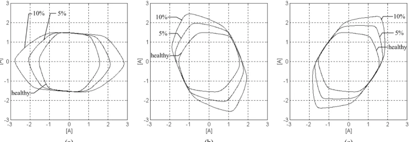
For the same load conditions and transformer winding connections mentioned above, Fig. 9 presents the experimental primary-side phase current Park's Vector patterns, for several percentages of shorted turns in the primary windings and for different faulty phases. The primary-side phase current Park's Vector pattern, corresponding to the healthy operation, differs slightly from the circular locus expected for ideal conditions, due to, among others, the supply voltage harmonic content and the minor reluctance seen from the central limb, with respect to the lateral limbs, Cardoso and Oliveira (3).
The occurrence of primary-side inter-turn short-circuits manifests itself in the deformation of the primary-side
phase current Park's Vector pattern corresponding to a healthy condition, leading to an elliptic representation, whose ellipticity increases with the severity of the fault and whose major axis orientation is associated to the faulty phase. Similar conclusions, concerning the trans-former supply current Park's Vector patterns, can be drawn for the occurrence of secondary inter-turn short circuits, under the same load conditions and winding connections, Cardoso and Oliveira (3).
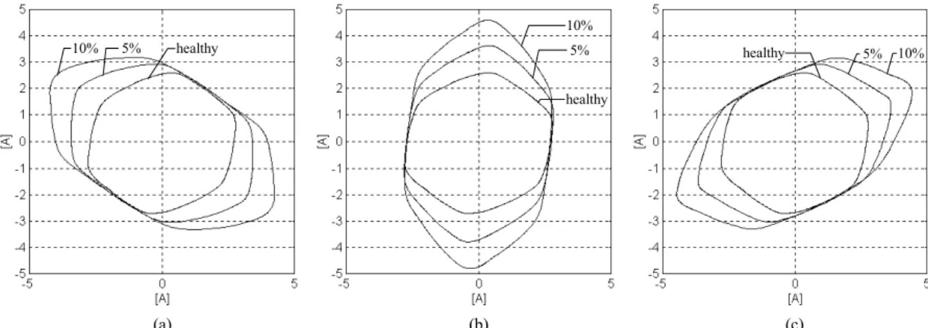
The simulated primary-side phase current Park's Vector patterns are presented in Fig. 10, which are in close agreement with the experimental results of Fig. 9. In the real industrial environment, the phase conductors of the delta connection are not usually available. Conse-quently, the diagnostic of the unit should be obtained from the line currents. Under this circumstances, the supply current Park's Vector patterns (Fig. 11 and Fig. 12), corresponding to the occurrence of inter-turn short- -circuits, present a global clockwise rotation of 30 degrees, with respect to the corresponding phase cur-rents Parks Vector patterns.
The transformer secondary current Park's Vector pattern doesn't provide any indication about inter-turn short-
(a) (b) (c)
Fig. 9: Experimental primary-side phase current Park's Vector patterns for the case of a Dyn5 connection and a balanced resistive load, with several percentages of permanent shorted turns in the primary windings and for different faulty phases: (a) phase R; (b) phase S; (c) phase T.
(a) (b) (c)
Fig. 10: Simulated primary-side phase current Park's Vector patterns for the case of a Dyn5 connection and a balanced resistive load, with several percentages of permanent shorted turns in the primary windings and for different faulty phases: (a) phase R; (b) phase S; (c) phase T.
5% 10% healthy 5% 10% healthy healthy 5% 10% 5% 10% healthy 5% 10% healthy healthy 5% 10% (a) (b) (c)
Fig. 11: Experimental primary-side line current Park's Vector patterns for the case of a Dyn5 connection and a balanced resistive load, with several percentages of permanent shorted turns in the primary windings and for different faulty phases: (a) phase R; (b) phase S; (c) phase T.
(a) (b) (c)
Fig. 12: Simulated primary-side line current Park's Vector patterns for the case of a Dyn5 connection and a balanced resistive load, with several percentages of permanent shorted turns in the primary windings and for different faulty phases: (a) phase R; (b) phase S; (c) phase T.
-circuits that may occur, either in the primary or in the secondary side of the transformer. However, it plays a very important role for discriminating the presence of unbalanced loads.
Intermittent faults
In order to simulate the behaviour of the transformer, under the occurrence of winding insulation intermittent failures, it is assumed that at the fault location an elec-tric arc takes place, Morante and Nicoletti (14). The arc voltage was modelled as a non-linear voltage source. The arc discharge occurs when the voltage across the faulty subwinding (2 adjacent turns ≈ 1%, in this case) exceeds a pre-determined threshold value.
For the case of the Dyn5 connection, a balanced resistor
load and 1% of intermittent shorted turns in the phase R
of the transformer primary winding, the simulated primary-side phase current Park's Vector pattern is shown in Fig. 13(a). For comparison purposes, the cor-responding healthy Park's Vector pattern is also in-cluded (dashed line). The analysis of this figure shows that is also possible to detect the fault, its severity and also to identify the faulty phase. Similar conclusions can
be drawn from the primary-side line current Park's Vector pattern, Fig. 13(b).
CONCLUSIONS
This paper presents a non-invasive approach for diag-nosing winding insulation failures in three-phase trans-formers. The on-line diagnosis is based on identifying the appearance of an elliptic pattern, corresponding to the transformer supply current Park's Vector representa-tion, whose ellipticity increases with the severity of the fault and whose major axis orientation is associated to the faulty phase.
Experimental and/or simulated test results were presented, for both permanent and intermittent winding insulation faults, which demonstrate the effectiveness of the diagnostic technique.
Further work is currently in progress, concerning the refinement of the proposed diagnostic technique, with the aim of dealing with the simultaneous occurrence of winding faults, unbalanced supply voltages, unbalanced loads, or even the surrounding presence of power elec-tronics equipment.
healthy 1% healthy 1% (a) (b)
Fig. 13: Simulated primary-side current Park's Vector patterns for the case of a Dyn5 connection and a balanced resistive load, with 1% of
shorted turns (intermittent) in the primary winding (phase R): (a) phase current; (b) line current.
ACKNOWLEDGEMENT
The authors wish to acknowledge the financial support of the Portuguese Foundation for Science and Technology, under Project Number POSI/EEI/ /14151/1998.
REFERENCES
1. Ashmore, C., "Transforming technology", Int.
Power Generation, Vol 22, No. 3, pp 25-26 (1999).
2. Wang, Z., "Artificial intelligence applications in
the diagnosis of power transformer incipient faults", Ph. D. thesis, Faculty of the Virginia Polytechnic Institute and State University (2000).
3. Cardoso, A. J. M. and Oliveira, L. M. R.,
"Condition monitoring and diagnostics of power transformers", Int. J. COMADEM, Vol 2, No. 3, pp 5-11 (1999).
4. Cardoso, A. J. M., "The Park's Vector Approach:
a general tool for diagnostics of electrical machines, power electronics and adjustable speed drives", Rec. 1997 IEEE Int. Symp. Diagnostics for Electrical Machines, Power Electronics and Drives, pp 261-269 (1997).
5. Oliveira, L. M. R. and Cardoso, A. J. M., "Three-
-phase, three-limb, steady-state transformer model: the case of a Ynzn connection", Proc. IASTED Int. Conf. "Power and Energy Systems", pp 491-472 (2000).
6. Oliveira, L. M. R. and Cardoso, A. J. M., "A
coupled electromagnetic transformer model for the analysis of winding inter-turn short-circuits", Rec. IEEE Int. Symp. Diagnostics for Electrical Machines, Power Electronics and Drives, pp 367-372 (2001).
7. IEEE Std. C57.12.58-1991, "IEEE guide for
conducting a transient voltage analysis of a dry- -type transformer coil", IEEE (1991).
8. IEEE Std. C37.91-2000, "IEEE guide for
protective relay applications to power transformers", IEEE (2000).
9. Barkan, P.; Damsky, B. L.; Ettlinger, L. F. and
Kotski, E. J., "Overpressure phenomena in distribution transformers with low impedance faults: experiment and theory", IEEE Trans. PAS, Vol 95, No. 1, pp 37-48 (1976).
10. Stigant, S. A. and Franklin, A. C., "The J&P
Transformer Book", 10th Edition, Newnes-
-Butterworths (1973).
11. Plummer, C. W.; Goedde, G. L.; Petit, E. L.;
Godbee, J. S. and Hennessey, M. G., "Reduction in distribution transformer failures rates and nuisance outages using improved lightning protection concepts", IEEE Trans. Power Delivery, Vol 10, No. 2, pp 768-777 (1995).
12. Lunsford, J. M. and Tobin, T. J., "Detection of and
protection for internal low-current winding faults in overhead distribution transformers", IEEE Trans. Power Delivery, Vol 12, No. 3, pp 1241-1249 (1997).
13. Yakamini, R. and Bronzeado, H., "Transformer
inrush calculations using a coupled electro-magnetic model", IEE Proc. Sci. Meas. Technol., Vol 141, No. 6, pp 491-498 (1994)
14. Gómez-Morante, M. and Nicoletti, D. W., "A
wavelet-based differential transformer protec-tion", IEEE Trans. Power Delivery, Vol 14, No. 4, pp 1351-1359 (1999).