IEEE Proof
Web Version
IEEE TRANSACTIONS ON ANTENNAS AND PROPAGATION, VOL. 62, NO. 1, JANUARY 2014 1
Spatially Confined UHF RFID Detection
With a Metamaterial Grid
Tiago A. Morgado, Jorge M. Alves, João S. Marcos, Stanislav I. Maslovski, Member, IEEE,
Jorge R. Costa, Senior Member, IEEE, Carlos A. Fernandes, Senior Member, IEEE, and
Mário G. Silveirinha, Member, IEEE
Abstract—The confinement of the detection region is one of the
most challenging issues in Ultra-High Frequency (UHF) Radio Fre-quency Identification (RFID) systems. Here, we propose a new par-adigm to confine the interrogation zone of standard UHF RFID systems. Our approach relies on the use of an all-planar metama-terial wire grid to block the radiation field (i.e., the far-field) of the reader antenna, and thereby obtain a spatially well-confined detec-tion region in the near-field. This soludetec-tion is analytically and nu-merically investigated, and then experimentally verified through near-field and tag-reading measurements, demonstrating its effec-tiveness and robustness under external perturbations.
Index Terms—Metamaterials, near-field UHF RFID, radio
fre-quency identification (RFID), wire media.
I. INTRODUCTION
R
ADIO FREQUENCY IDENTIFICATION (RFID) is an increasingly popular technology that enables detecting and recognizing objects tagged with a unique identification code carried by an electronic chip attached to an antenna the RFID tag [1]–[3]. A typical RFID system comprises, in addition to RFID tags, an RFID reader. The reader is connected to one or more antennas that are used to query the tags within its detec-tion range.The world assigned RFID frequency bands range from 125 kHz up to 2.4 GHz [1]–[4]. In the Low Frequency (LF) and High Frequency (HF) bands the communication between the reader and the tags is made by magnetic (inductive) near-field coupling and, therefore, the detection range is inherently confined to few tens of centimeters [1]–[4]. Quite differently, in the Ultra-High Frequency (UHF) and microwave bands the energy coupling to
Manuscript received April 15, 2013; revised August 07, 2013; accepted September 24, 2013. Date of publication October 23, 2013; date of cur-rent version December 31, 2013. This work was supported in part by Instituto de Telecomunicações under projects IT/LA/P01080/2011 and PEst-OE/EEI/LA0008/2013.
T. A. Morgado, J. M. Alves, J. S. Marcos, S. I. Maslovski, and M. G. Sil-veirinha are with the Departamento de Engenharia Electrotécnica, Instituto de Telecomunicações, Universidade de Coimbra Pólo II, 3030-290 Coimbra, Por-tugal (e-mail: tiago.morgado@co.it.pt; joccca@gmail.com; jmarcos@co.it.pt; stas@co.it.pt; mario.silveirinha@co.it.pt).
J. R. Costa is with the Instituto de Telecomunicações, 1049-001 Lisboa, Portugal, and also with the Instituto Universitário de Lisboa (ISCTE-IUL), 1649-026 Lisboa, Portugal (e-mail: jorge.costa@lx.it.pt).
C. A. Fernandes is with the Instituto de Telecomunicações, and with Instituto Superior Técnico, 1049-001 Lisboa, Portugal (e-mail: carlos.fernandes@lx.it. pt).
Digital Object Identifier 10.1109/TAP.2013.2287027
the tag antenna is made through propagating electromagnetic waves and hence a detection region of several meters is possible [1]–[4].
Currently, because of the lower unit cost of the UHF RFID passive tags as compared to the price of the other passive tags [5], [6] and the higher transmission rates, data storage, and ex-change capacities available in the UHF band as compared to the LF and HF bands, UHF RFID technology is the preferred and established choice for mass applications. However, there are still important issues holding back its use in relevant sce-narios. In particular, one major challenge in current UHF RFID systems concerns the confinement of the detection region to pre-vent unwanted readings of tags located outside a desired inter-rogation volume. This is of particular importance in scenarios where the RFID system must be operational in open environ-ments and where it is not feasible to place electromagnetic iso-lation barriers to confine the radiation field. An example is the recording of information in a roll of closely spaced tags. For such application, the printer “antenna” is required to interact very selectively with the desired tag so that the same informa-tion is not accidentally written in two adjacent posiinforma-tions of the tag inlay rolls. Another potential application is related to an ac-cess control point of a room or facility based on a UHF RFID system. This requires that the interrogation volume is spatially confined to a very small region, so that the permission of ac-cess is granted exclusively when the acac-cess card (containing the RFID tag) is placed in front and near the reader, similar to what can be achieved in the LF and HF bands with more expensive tags.
One possibility to have short-range detection in the UHF band relies on reader antennas based on inductive coupling [7]–[11]. A drawback of such a solution is that it may require the devel-opment of new tags different from the typical UHF RFID tags that operate in backscattering mode. Another possibility is based on leaking microstrip lines, and was recently suggested in [12], [13]. This option can be readily integrated with existing com-mercial UHF RFID readers and enables reliable tag detection in selective self-confined interrogation volumes. Nevertheless, it requires structures with several wavelengths in order to ra-diate most of the microstrip waveguide energy, and avoid in this manner complications related to reflections and/or radiation at the end of the transmission line. This restriction on the physical size can make the leaking structure unsuitable for some appli-cations.
Here, we propose a simple approach to confine the interro-gation zone of UHF RFID systems to a desired region of space, and thereby ensure short-range univocal detection of tags, which
IEEE Proof
Web Version
is based on the apparently paradoxical concept of a“radiation-less antenna”. The electromagnetic field emitted by a source is formed by a radiation far-field and by a near-field. The far-field is associated with a flow of electromagnetic energy away from the source, and can be potentially detected at long distances. To get rid of the radiation field, we suggest using a metamaterial grid (see Fig. 1) formed by an array of metallic strips [14]–[17] to block the radiation field (in the direction of the tag) of a con-ventional dipole antenna, obtaining in this manner a “one-direc-tion radia“one-direc-tionless antenna”, such that the electromagnetic field emission spectrum along the tag’s direction is formed mainly by the near-field. Despite the absence of the far-field in the tag’s di-rection, the antenna can still be coupled to the RFID tag through the near-field. The near-field has essentially a reactive nature and decays relatively fast away from the source (e.g., for a point source it decays as in contrast to the decay rate of the far-field [4]; is the distance from the source to the observa-tion point). Ideally, if the electric dipole is placed in a closed opaque cavity with one of the walls replaced by the wire grid, it does not radiate any power in the absence of absorption (e.g., in the absence of a nearby RFID tag). Therefore, in such con-ditions one has an “omnidirectional radiationless antenna”. In our setup (Fig. 1), for simplicity, we consider an open structure such that the power radiated along the direction perpendicular to the metamaterial grid is negligible, and hence, we designate the system as “one-direction radiationless antenna”. Notice that when an RFID tag is placed in the close vicinity of the radia-tionless antenna, it creates a reflected near-field wave that al-lows for a power flux between the antenna and the tag, with no direct radiation from the reader antenna to the far-field. Because the near-field intrinsically decays quite fast, this provides a spa-tially well-confined detection region. Our system still operates in a backscattering mode, and therefore is fully compatible with the existing commercial UHF RFID readers and tags. On the other hand, in contrast to the leaking microstrip antenna [12], [13], the proposed near-field UHF RFID system does not suffer from critical physical size constraints. In practice, it is enough to ensure that both the width and the height of the wire grid are slightly larger than the largest characteristic dimension of the reader antenna.
This paper is organized as follows. In Section II, we char-acterize the electromagnetic response of the metamaterial wire grid. In Section III, we theoretically and experimentally study the resolving properties of the wire grid in detecting metallic targets and RFID tags. Then, in Section IV the coverage areas within the interrogation zone of the proposed near-field UHF RFID system are analyzed. Finally, in Section V the conclusions are drawn.
II. METAMATERIALWIREGRIDCHARACTERIZATION
Here, we describe and characterize the key element of the proposed near-field UHF RFID system (Fig. 1): the metama-terial wire grid (Fig. 2). It consists of a planar wire grid with
length and width ( is the
free-space wavelength), formed by long and thin copper strip wires with width mm. The grid period (i.e., the dis-tance between adjacent wires) is mm. The wire grid is
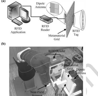
Fig. 1. Metamaterial grid-based near-field UHF RFID system: (a) Schematic layout; (b) Photo of the experimental setup.
Fig. 2. Geometry of the metamaterial wire grid: a planar wire grid with length and width , formed by -oriented thin and long copper strips with width mm, printed on the surface of a 1.6 mm thick fiber glass (FR-4) board. The distance between adjacent metallic strips is mm.
printed on an FR-4 substrate with dielectric constant , loss tangent , and thickness 1.6 mm.
In the long wavelength limit , the considered wire grid can be described using homogenization techniques [18]–[20]. For dense wire grids , the reflection and transmission field coefficients for the extraordinary TM waves (i.e., the magnetic field is orthogonal to the -axis) are [14],
(1) (2)
IEEE Proof
Web Version
MORGADO et al.: SPATIALLY CONFINED UHF RFID DETECTION 3
Fig. 3. Amplitude of the transmission coefficient of the wire grid as a func-tion of the normalized transverse wave vector . (i) Analytical result ((2)); (ii) Full-wave simulation result [21].
where is given by (12) of [14], is the wave number (where is the speed of light in vacuum),
and is the transverse wave vector. may be regarded as the transfer function of the wire grid.
In Fig. 3 we show the amplitude of the transmission coeffi-cient as a function of the transverse wave vector , using both the analytical formula ((2)) (solid curves) and full-wave simu-lations [21] (dashed curves). As seen, there is an overall good agreement between the analytical and full-wave simulation re-sults.
Fig. 3 shows that the amplitude of is much higher for the evanescent waves than for the propagating waves . This implies that the considered wire grid is highly transparent for the evanescent waves and almost opaque for the propagating waves [14], so that the radiating system of Fig. 1 is indeed a “one-direction radiationless antenna”. One can say that the metamaterial wire grid operates as a high-pass spa-tial-frequency filter that blocks the low-frequency spatial har-monics (associated with the far-field) and lets through the high-frequency components of the spatial spectrum (associated with the near-field). Unlike what happens in a typical silver lens at optical frequencies [22], in our wire grid there is no enhance-ment of the evanescent fields due to the resonant excitation of surface plasmons. Instead, there is a simple suppression of the low-frequency components of the spatial spectrum [14]. In simple physical terms, this suppression can be understood from the fact that the waves with small transverse wave numbers (propagating waves) are unable to sense the spacing between the metallic strips and simply “see” a PEC screen, which causes them to be strongly reflected. This spatial-frequency filtering ef-fect may enable the near-field confinement and this will be ex-plored here in the context of near-range RFID detection in the UHF frequency band.
III. DISCRIMINATION OFMETALLICTARGETS ANDRFID TAGS
Next, we evaluate the potential of the metamaterial wire grid (Fig. 2) operated in backscattering mode to discriminate objects (metallic targets and RFID tags) separated by subwavelength distances.
Fig. 4. (a) Geometry of the system used to measure the backscattered field. It consists of a wire grid, a moving probe antenna, and a set of metallic targets behind the grid. (b) Photo of the experimental setup. (c) and (d) Amplitude of the backscattered field as a function of the position of the probe antenna. (c) with the wire grid; (d) without the wire grid. Solid curves: numerical results based on the theoretical model of [23]; Discrete symbols: experimental results.
; (ii) ; (iii) ; (iv) .
To begin with, we consider the geometry depicted in Fig. 4(a)–(b). It shows a wire grid, a probe (or reader) dipole antenna placed in front of the wire grid, and a set of two -oriented thin cylindrical metallic targets behind the wire grid. The metallic targets and the probe antenna are at a distance mm from the wire grid. For a fixed frequency MHz, we consider four different spacings between the
targets: , and .
In Fig. 4(c)–(d), we depict the backscattered field due to the metallic targets, , as a function of the normalized position of the probe antenna , both with (Fig. 4(c)) and without (Fig. 4(d)) the wire grid. The backscattered field is plotted in dB and is normalized to the maximum amplitude. The solid curves in Fig. 4(c)–(d) rep-resent the results obtained using an analytical model based on a straightforward generalization of the theory of [23], whereas the discrete symbols correspond to experimental results obtained by detecting the perturbations on the return loss of the antenna
. Specifically, , where is the
measured complex valued reflection coefficient at the probe an-tenna terminals with the metallic targets, and is the same quantity obtained in an initial calibration measurement with the metallic targets removed. Both and were measured using a vector network analyzer (R&S ZVB20) that feeds the probe antenna with an input power dBm. It was as-sumed that to a first approximation the perturbation of the return loss is proportional to the backscattered field .
As can be seen from Fig. 4(c)–(d), the agreement between the theoretical and the experimental results is very good, especially for the scenario where the wire grid is present (Fig. 4(c)). More-over, notwithstanding the subwavelength distances between the two metallic targets, they are clearly discriminated when the wire grid is in place. In contrast, when the wire grid is removed (Fig. 4(d)), the two metallic targets are hardly discriminated. These results clearly show that the wire grid allows enhancing the resolving properties of a system operating in backscattering
IEEE Proof
Web Version
Fig. 5. (a) Sketch of the setup used to investigate the spatial confinement in the RFID tag detection, showing the set of three RFID tags behind the grid. (b) Photo of the experimental setup. (c) Experimental reading scores of the three RFID tags separated by . Solid lines: with the wire grid; dashed lines: wire grid is removed. Without wire grid the number of readings per second is the same for all the tags, independent of the position of the reading antenna.
regime. In [14] a similar result was demonstrated for a system comprising separate source and receiver.
We also investigated if the enhanced resolving properties of the wire grid may help to discriminate RFID tags separated by subwavelength distances. To this end, now we consider a set of three -oriented RFID tags (ALIEN ALN-9540 “squiggle” tags) placed behind the wire grid (at the same distance
mm as before) and separated by a distance (see Fig. 5(a)–(b)). In this setup, the dipole-type antenna is connected to a RFID reader (Sirit Infinity 510) that feeds the antenna with
an input power dBm.
Fig. 5(c) shows the number of readings per second of each RFID tag as a function of the normalized position of the probe antenna , in the presence of the wire grid (solid lines) as well as in the absence of the wire grid (dashed lines). As one can see from Fig. 5(c), the RFID tags are only spatially dis-criminated when the wire grid is placed between the probe an-tenna and the tags. Without the wire grid, the identification of the RFID tags is spatially overlapped, and hence, their relative position cannot be determined with assurance of reasonable ac-curacy. It is worth noting that without the grid the number of readings per second of each RFID tag is lower than when the wire grid is present (around one third) [see Fig. 5(c)]. This is simply a consequence of tag collision problems.
IV. THEINTERROGATIONZONE
In order to study the potentials of using the wire grid to con-fine the detection region of UHF RFID systems, we have mea-sured the coverage area associated with the interrogation zone (i.e., the area wherein the RFID tags are detected), both with and without the wire grid. To this end, we have placed a -oriented RFID tag in the wrist of a robotic arm and then we have regis-tered the reading score for the tag as it moves in the xoz plane (see Fig. 6(a)–(b)). Unlike in the setup of Section III (where the antenna moves and the obstacles, either the metallic rods or the tags, remain at the same position), in this case the dipole an-tenna is fixed behind the grid (at a distance mm of the grid) and the tag under test moves on a plane. The results ob-tained for the coverage areas are reported in Fig. 6(c)–(d). The
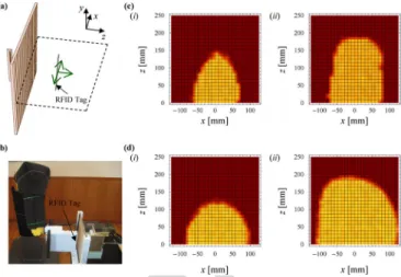
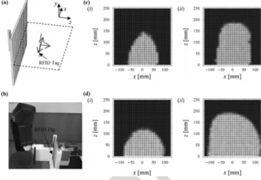
Fig. 6. (a) Sketch of the setup used to measure the coverage areas of our near-field UHF RFID system. (b) Photo of the experimental setup. (c) and (d) Cov-erage diagrams of our near-field UHF RFID system for different input powers of the probe antenna. (c) with the wire grid: dBm, (ii)
dBm; (d) without the wire grid: dBm, (ii) dBm.
bright (dark) areas represent the region where the tag is (is not) detected.
The property that readily stands out from Fig. 6(c)–(d) is the enhanced confinement made possible by the metamaterial wire grid. It is seen that, for a similar depth of detection in the -direc-tion, the system with wire grid (Fig. 6(c)) always ensures an in-terrogation zone laterally more confined. This is a consequence of the near-field collimation performed by the metamaterial wire grid—rooted in the spatial-frequency filtering effect discussed in Section II—which avoids the lateral spreading of the electro-magnetic field. Very similar spatially confined detection regions can in principle also be obtained for circularly polarized reader antennas by using two mutually perpendicular wire grids instead of a single wire grid. Such confinement of the near-field of the reader antenna may be interesting in scenarios where very well spatially defined detection regions are sought—for example, in cashier conveyor belts of supermarkets. In this case, besides the high lateral spatial confinement, a considerable depth of de-tection along the -direction can be useful. In Fig. 6(c)(ii) we show a depth of detection along the -direction of about 20 cm. Larger depths of detection are possible if the lateral confinement is slightly compromised (e.g., if the antenna is fed with higher input powers). In fact, another advantage of the proposed solu-tion is its hybrid operasolu-tion potentials, since by using simultane-ously different reader antennas the interrogation zone can either be very sharp or broad.
Fig. 6(c)–(d) also shows that to achieve comparable depths of detection, the system with the wire grid always needs a higher input power than the system without wire grid. This is because the wire grid filters out the propagating waves (see Fig. 3), which are the responsible for the most of the power flow. This confirms that the system formed by the dipole and the grid cor-responds to a nearly “one-direction radiationless antenna”.
In Fig. 7, we plot the coverage area of the interrogation zone as a function of the distance between the reader antenna and the wire grid. As expected, as the distance increases the cov-erage area becomes smaller. Indeed, because the wire grid op-erates as a high-pass spatial-frequency filter, only the near-field
IEEE Proof
Web Version
MORGADO et al.: SPATIALLY CONFINED UHF RFID DETECTION 5
Fig. 7. Interrogation zone coverage area as a function of distance between the reader dipole antenna and the wire grid for a fixed input power
dBm.
Fig. 8. Interrogation zone coverage area as a function of the normalized input power. with wire grid; (ii) without wire grid.
of the reader antenna effectively contributes to the transmitted field. From Fig. 7 and from the corresponding coverage dia-grams, we can set a rough upper limit for the distance between the reader antenna and the wire grid: .
In Fig. 8 we depict the experimentally measured coverage areas within the interrogation zone as functions of the nor-malized input power ( corresponds to the minimum reading power, i.e., the power for which the coverage area is zero), both when the wire grid is present (Fig. 8(i)) and when it is absent (Fig. 8(ii)). It is seen that the coverage area varies significantly more slowly with the input power with the wire grid (Fig. 8(i)) than without the wire grid (Fig. 8(ii)). This means that with the wire grid the performance of the system is less sensitive to variations in the power supplied to the system. Such a feature may be interesting in the RFID context, since it makes the system more robust to external perturbations.
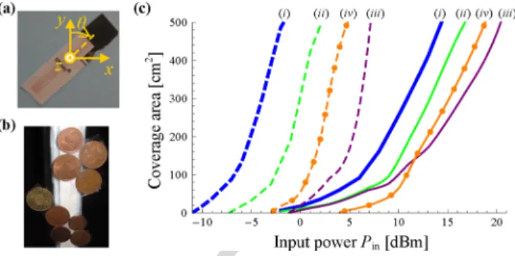
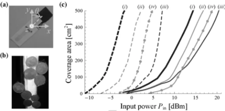
To further investigate this, we studied the system response when the RFID tag is either rotated around the -axis (Fig. 9(a)), or when it is masked by small objects (coins) (Fig. 9(b)).
In Fig. 9(c) we show the interrogation zone coverage areas as functions of the input power for different angles of rotation of the tag and also for the case where the tag is obstructed by
Fig. 9. (a) Photo of the rotated RFID tag. (b) Photo of the RFID tag obstructed by the presence of coins. (c) Coverage areas as a function of the input power in dBm. Solid curves: with wire grid; dashed curves: without wire grid. Results for the unperturbed system, i.e., for the scenario where the RFID tag is -ori-ented and there are no coins obstructing it; (ii), and (iii) results for different orientations of the RFID tag, ; and , respectively. (iv) Results for the scenario where the RFID tag is obstructed by coins.
coins. Fig. 9(c) reveals that the shift experienced by the cov-erage area curves when the system is under an external pertur-bation (caused either by the RFID tag rotation or by the pres-ence of coins) is invariably smaller in the scenario where the metamaterial wire grid is present (solid curves) than when it is absent (dashed curves). Therefore, these results show that the system with metamaterial wire grid is undoubtedly more robust to external perturbations. This is so because the near-field of a radiationless antenna is intrinsically confined to its vicinity. Moreover, it is interesting to note from Fig. 9(c) that, in the sce-nario where the wire grid is present, for each specific value of the input power, the RFID tag can be detected either when the tag is unobstructed (in a wider region) or obstructed (in a smaller area) by coins (see solid blue and orange curves of Fig. 9(c)), in contrast to what happens without the wire grid (see dashed blue and orange curves of Fig. 9(c)).
V. CONCLUSION
In this work, we have introduced a new paradigm to spatially confine the detection region of UHF RFID systems. The pro-posed solution exploits the near-field collimation properties of a planar metamaterial wire grid, and relies on the idea of a “radi-ationless antenna” coupled to standard tags through the electric near-field, unlike the more common RFID systems operating with tags that couple through the magnetic near-field. A pro-totype of the wire grid-RFID antenna was designed, fabricated, and tested using standard UHF RFID reader equipment and tags. Near-field and tag-reading measurements reveal an evident con-finement of the detection region, as well as a lower sensitivity of the system to external perturbations, when the metamaterial wire grid is present. The simplicity, effectiveness, and robust-ness of the reported solution suggest promising applications in near-range RFID detection at UHF or even at microwave fre-quencies.
REFERENCES
[1] K. Finkenzeller, RFID Handbook: Fundamentals and Applications in
Contactless Smart Cards and Identification, 2nd ed. New York, NY,
USA: Wiley, 2003.
[2] R. Want, “An introduction to RFID technology,” IEEE Pervasive
IEEE Proof
Web Version
[3] V. Chawla and D. Sam Ha, “An overview of passive RFID,” IEEE
Commun. Mag., vol. 4, pp. 11–17, Sep. 2007.
[4] P. V. Nikitin, K. V. S. Rao, and S. Lazar, “An overview of near field UHF RFID,” in Proc. IEEE Int. Conf. RFID, Grapevine, TX, USA, Mar. 26–28, 2007, pp. 167–174.
[5] K. Rao, P. Nikitin, and S. Lam, “Antenna design for UHF RFID tags: A review and a practical application,” IEEE Trans. Antennas Propag., vol. 53, pp. 3870–3876, Dec. 2005.
[6] M. Lieshout, L. Grossi, G. Spinelli, S. Helmus, L. Kool, L. Pennings, R. Stap, T. Veugen, B. der Waaij, and C. Borean, “RFID Technolo-gies: Emerging Issues, Challenges, and Policy Options,” Institute for Prospective Technological Studies, European Comission, Tech. Rep., EUR 22770 EN, 2007.
[7] H.-W. Son and C.-S. Pyo, “Design of RFID tag antennas using an in-ductively coupled feed,” Electron. Lett., vol. 41, pp. 994–996, Sep. 2005.
[8] W. Choi, J.-S. Kim, J.-H. Bae, G. Choi, and J.-S. Chae, “Near-field antenna for RFID smart shelf in UHF,” in Proc. IEEE Antennas Propag.
Soc. Int. Symp., Charleston, SC, USA, Jun. 1–5, 2009, pp. 1449–1451.
[9] Y. S. Ong, X. Qing, C. K. Goh, and Z. N. Chen, “A segmented loop antenna for UHF near-field RFID,” in Proc. IEEE. Antennas Propag.
Soc. Int. Symp., Toronto, ON, Canada, Jul. 11–17, 2010, pp. 1–4.
[10] A. Shameli, A. Safarin, A. Rofougaran, M. Rofougaran, J. Castaneda, and F. De Flaviis, “A UHF near-field RFID system with fully inte-grated transponder,” IEEE Trans. Microw. Theory Tech., vol. 56, pp. 1267–1277, May 2008.
[11] X. Liu and Z. Yang, “Dual-printed-dipoles reader antenna for UHF near-field RFID applications,” IEEE Antennas Wireless Propag. Lett., pp. 239–242, Feb. 2011.
[12] C. R. Medeiros, J. R. Costa, and C. A. Fernandes, “RFID smart shelf with confined detection volume at UHF,” IEEE Antennas Wireless
Propag. Lett., vol. 7, pp. 773–776, Oct. 2008.
[13] C. R. Medeiros, J. R. Costa, and C. A. Fernandes, “RFID reader an-tennas for tag detection in self-confined volumes at UHF,” IEEE
An-tennas Propag. Mag., vol. 53, pp. 39–50, Apr. 2011.
[14] G. Fedorov, S. I. Maslovski, A. V. Dorofeenko, I. A. Ryzhikov, and S. Tretyakov, “Subwavelength imaging: Resolution enhancement using metal wire gratings,” Phys. Rev. B, vol. 73, p. 035409, Jan. 2006. [15] G. Lovat, “Near-field shielding effectiveness of 1-D periodic planar
screens with 2-D near-field sources,” IEEE Trans. Electromagn.
Compat., vol. 51, pp. 708–719, Aug. 2009.
[16] P. Burghignoli, G. Lovat, F. Capolino, D. R. Jackson, and D. R. Wilton, “Highly polarized, directive radiation from a Fabry-Pérot cavity leaky-wave antenna based on a metal strip grating,” IEEE Trans. Antennas
Propag., vol. 58, pp. 3873–3883, Dec. 2010.
[17] R. Araneo, G. Lovat, and S. Celozzi, “Shielding effectiveness of pe-riodic screens against finite high-impedance near-field sources,” IEEE
Trans. Electromagn. Compat., vol. 53, pp. 706–716, Aug. 2011.
[18] P. A. Belov, R. Marqués, S. I. Maslovski, I. S. Nefedov, M. G. Silveir-inha, C. R. Simovski, and S. A. Tretyakov, “Strong spatial dispersion in wire media in the very large wavelength,” Phys. Rev. B, vol. 67, p. 113103, Mar. 2003.
[19] M. G. Silveirinha, “Nonlocal homogenization model for a periodic array of -negative rods,” Phys. Rev. E, vol. 73, p. 046612, Apr. 2006. [20] S. I. Maslovski and M. G. Silveirinha, “Nonlocal permittivity from a quasistatic model for a class of wire media,” Phys. Rev. B, vol. 80, p. 245101, Dec. 2009.
[21] CST Microwave Studio 2012 [Online]. Available: (http://www.cst. com)
[22] N. Fang, H. Lee, C. Sun, and X. Zhang, “Sub-diffraction-limited optical imaging with a silver superlens,” Science, vol. 308, pp. 534–537, Apr. 2005.
[23] M. G. Silveirinha, C. R. Medeiros, C. A. Fernandes, and J. R. Costa, “Resolving subwavelength objects with a crossed wire mesh superlens operated in backscattering mode,” New. J. Phys., vol. 13, pp. 1–13, Jan. 2011.
Tiago A. Morgado was born in Coimbra, Portugal,
in 1983. He received the “Licenciado” degree in electrical and computer engineering and the Ph.D. degree in electrical and computer engineering (spe-cialty of Telecommunications) from the University of Coimbra, Portugal, in 2007 and 2012, respec-tively.
He is currently a Post-Doc researcher at the Insti-tuto de Telecomunicações, Coimbra, Portugal. His current research interests concern electromagnetic metamaterials and their applications.
Jorge M. Alves received the “Mestado Integrado”
degree in electrical engineering from the University of Coimbra, Portugal, in 2011. His master thesis de-scribes an UHF RFID near field system based on a planar wire grid.
João S. Marcos received the B.E. and M.E. degrees
from ISCTE-IUL, Lisbon, Portugal, in 2005 and 2011, respectively.
After one year of professional experience at Siemens Networks in a group of Planning and Optimization of Mobile Networks, he returned to the university, this time in Coimbra, Portugal, to embrace a project in Computer Vision for two years. Since 2008 he has been working in different projects at the Microwave Laboratory of Instituto de Telecomunicações—Coimbra.
Stanislav I. Maslovski, photograph and biography not available at the time of
publication.
Jorge R. Costa, photograph and biography not available at the time of
publica-tion.
Carlos A. Fernandes, photograph and biography not available at the time of
publication.
Mário G. Silveirinha, photograph and biography not available at the time of
IEEE Proof
Print Version
IEEE TRANSACTIONS ON ANTENNAS AND PROPAGATION, VOL. 62, NO. 1, JANUARY 2014 1
Spatially Confined UHF RFID Detection
With a Metamaterial Grid
Tiago A. Morgado, Jorge M. Alves, João S. Marcos, Stanislav I. Maslovski, Member, IEEE,
Jorge R. Costa, Senior Member, IEEE, Carlos A. Fernandes, Senior Member, IEEE, and
Mário G. Silveirinha, Member, IEEE
Abstract—The confinement of the detection region is one of the
most challenging issues in Ultra-High Frequency (UHF) Radio Fre-quency Identification (RFID) systems. Here, we propose a new par-adigm to confine the interrogation zone of standard UHF RFID systems. Our approach relies on the use of an all-planar metama-terial wire grid to block the radiation field (i.e., the far-field) of the reader antenna, and thereby obtain a spatially well-confined detec-tion region in the near-field. This soludetec-tion is analytically and nu-merically investigated, and then experimentally verified through near-field and tag-reading measurements, demonstrating its effec-tiveness and robustness under external perturbations.
Index Terms—Metamaterials, near-field UHF RFID, radio
fre-quency identification (RFID), wire media.
I. INTRODUCTION
R
ADIO FREQUENCY IDENTIFICATION (RFID) is an increasingly popular technology that enables detecting and recognizing objects tagged with a unique identification code carried by an electronic chip attached to an antenna the RFID tag [1]–[3]. A typical RFID system comprises, in addition to RFID tags, an RFID reader. The reader is connected to one or more antennas that are used to query the tags within its detec-tion range.The world assigned RFID frequency bands range from 125 kHz up to 2.4 GHz [1]–[4]. In the Low Frequency (LF) and High Frequency (HF) bands the communication between the reader and the tags is made by magnetic (inductive) near-field coupling and, therefore, the detection range is inherently confined to few tens of centimeters [1]–[4]. Quite differently, in the Ultra-High Frequency (UHF) and microwave bands the energy coupling to
Manuscript received April 15, 2013; revised August 07, 2013; accepted September 24, 2013. Date of publication October 23, 2013; date of cur-rent version December 31, 2013. This work was supported in part by Instituto de Telecomunicações under projects IT/LA/P01080/2011 and PEst-OE/EEI/LA0008/2013.
T. A. Morgado, J. M. Alves, J. S. Marcos, S. I. Maslovski, and M. G. Sil-veirinha are with the Departamento de Engenharia Electrotécnica, Instituto de Telecomunicações, Universidade de Coimbra Pólo II, 3030-290 Coimbra, Por-tugal (e-mail: tiago.morgado@co.it.pt; joccca@gmail.com; jmarcos@co.it.pt; stas@co.it.pt; mario.silveirinha@co.it.pt).
J. R. Costa is with the Instituto de Telecomunicações, 1049-001 Lisboa, Portugal, and also with the Instituto Universitário de Lisboa (ISCTE-IUL), 1649-026 Lisboa, Portugal (e-mail: jorge.costa@lx.it.pt).
C. A. Fernandes is with the Instituto de Telecomunicações, and with Instituto Superior Técnico, 1049-001 Lisboa, Portugal (e-mail: carlos.fernandes@lx.it. pt).
Digital Object Identifier 10.1109/TAP.2013.2287027
the tag antenna is made through propagating electromagnetic waves and hence a detection region of several meters is possible [1]–[4].
Currently, because of the lower unit cost of the UHF RFID passive tags as compared to the price of the other passive tags [5], [6] and the higher transmission rates, data storage, and ex-change capacities available in the UHF band as compared to the LF and HF bands, UHF RFID technology is the preferred and established choice for mass applications. However, there are still important issues holding back its use in relevant sce-narios. In particular, one major challenge in current UHF RFID systems concerns the confinement of the detection region to pre-vent unwanted readings of tags located outside a desired inter-rogation volume. This is of particular importance in scenarios where the RFID system must be operational in open environ-ments and where it is not feasible to place electromagnetic iso-lation barriers to confine the radiation field. An example is the recording of information in a roll of closely spaced tags. For such application, the printer “antenna” is required to interact very selectively with the desired tag so that the same informa-tion is not accidentally written in two adjacent posiinforma-tions of the tag inlay rolls. Another potential application is related to an ac-cess control point of a room or facility based on a UHF RFID system. This requires that the interrogation volume is spatially confined to a very small region, so that the permission of ac-cess is granted exclusively when the acac-cess card (containing the RFID tag) is placed in front and near the reader, similar to what can be achieved in the LF and HF bands with more expensive tags.
One possibility to have short-range detection in the UHF band relies on reader antennas based on inductive coupling [7]–[11]. A drawback of such a solution is that it may require the devel-opment of new tags different from the typical UHF RFID tags that operate in backscattering mode. Another possibility is based on leaking microstrip lines, and was recently suggested in [12], [13]. This option can be readily integrated with existing com-mercial UHF RFID readers and enables reliable tag detection in selective self-confined interrogation volumes. Nevertheless, it requires structures with several wavelengths in order to ra-diate most of the microstrip waveguide energy, and avoid in this manner complications related to reflections and/or radiation at the end of the transmission line. This restriction on the physical size can make the leaking structure unsuitable for some appli-cations.
Here, we propose a simple approach to confine the interro-gation zone of UHF RFID systems to a desired region of space, and thereby ensure short-range univocal detection of tags, which
IEEE Proof
Print Version
is based on the apparently paradoxical concept of a“radiation-less antenna”. The electromagnetic field emitted by a source is formed by a radiation far-field and by a near-field. The far-field is associated with a flow of electromagnetic energy away from the source, and can be potentially detected at long distances. To get rid of the radiation field, we suggest using a metamaterial grid (see Fig. 1) formed by an array of metallic strips [14]–[17] to block the radiation field (in the direction of the tag) of a con-ventional dipole antenna, obtaining in this manner a “one-direc-tion radia“one-direc-tionless antenna”, such that the electromagnetic field emission spectrum along the tag’s direction is formed mainly by the near-field. Despite the absence of the far-field in the tag’s di-rection, the antenna can still be coupled to the RFID tag through the near-field. The near-field has essentially a reactive nature and decays relatively fast away from the source (e.g., for a point source it decays as in contrast to the decay rate of the far-field [4]; is the distance from the source to the observa-tion point). Ideally, if the electric dipole is placed in a closed opaque cavity with one of the walls replaced by the wire grid, it does not radiate any power in the absence of absorption (e.g., in the absence of a nearby RFID tag). Therefore, in such con-ditions one has an “omnidirectional radiationless antenna”. In our setup (Fig. 1), for simplicity, we consider an open structure such that the power radiated along the direction perpendicular to the metamaterial grid is negligible, and hence, we designate the system as “one-direction radiationless antenna”. Notice that when an RFID tag is placed in the close vicinity of the radia-tionless antenna, it creates a reflected near-field wave that al-lows for a power flux between the antenna and the tag, with no direct radiation from the reader antenna to the far-field. Because the near-field intrinsically decays quite fast, this provides a spa-tially well-confined detection region. Our system still operates in a backscattering mode, and therefore is fully compatible with the existing commercial UHF RFID readers and tags. On the other hand, in contrast to the leaking microstrip antenna [12], [13], the proposed near-field UHF RFID system does not suffer from critical physical size constraints. In practice, it is enough to ensure that both the width and the height of the wire grid are slightly larger than the largest characteristic dimension of the reader antenna.
This paper is organized as follows. In Section II, we char-acterize the electromagnetic response of the metamaterial wire grid. In Section III, we theoretically and experimentally study the resolving properties of the wire grid in detecting metallic targets and RFID tags. Then, in Section IV the coverage areas within the interrogation zone of the proposed near-field UHF RFID system are analyzed. Finally, in Section V the conclusions are drawn.
II. METAMATERIALWIREGRIDCHARACTERIZATION
Here, we describe and characterize the key element of the proposed near-field UHF RFID system (Fig. 1): the metama-terial wire grid (Fig. 2). It consists of a planar wire grid with
length and width ( is the
free-space wavelength), formed by long and thin copper strip wires with width mm. The grid period (i.e., the dis-tance between adjacent wires) is mm. The wire grid is
Fig. 1. Metamaterial grid-based near-field UHF RFID system: (a) Schematic layout; (b) Photo of the experimental setup.
Fig. 2. Geometry of the metamaterial wire grid: a planar wire grid with length and width , formed by -oriented thin and long copper strips with width mm, printed on the surface of a 1.6 mm thick fiber glass (FR-4) board. The distance between adjacent metallic strips is mm.
printed on an FR-4 substrate with dielectric constant , loss tangent , and thickness 1.6 mm.
In the long wavelength limit , the considered wire grid can be described using homogenization techniques [18]–[20]. For dense wire grids , the reflection and transmission field coefficients for the extraordinary TM waves (i.e., the magnetic field is orthogonal to the -axis) are [14],
(1) (2)
IEEE Proof
Print Version
MORGADO et al.: SPATIALLY CONFINED UHF RFID DETECTION 3
Fig. 3. Amplitude of the transmission coefficient of the wire grid as a func-tion of the normalized transverse wave vector . (i) Analytical result ((2)); (ii) Full-wave simulation result [21].
where is given by (12) of [14], is the wave number (where is the speed of light in vacuum),
and is the transverse wave vector. may be regarded as the transfer function of the wire grid.
In Fig. 3 we show the amplitude of the transmission coeffi-cient as a function of the transverse wave vector , using both the analytical formula ((2)) (solid curves) and full-wave simu-lations [21] (dashed curves). As seen, there is an overall good agreement between the analytical and full-wave simulation re-sults.
Fig. 3 shows that the amplitude of is much higher for the evanescent waves than for the propagating waves . This implies that the considered wire grid is highly transparent for the evanescent waves and almost opaque for the propagating waves [14], so that the radiating system of Fig. 1 is indeed a “one-direction radiationless antenna”. One can say that the metamaterial wire grid operates as a high-pass spa-tial-frequency filter that blocks the low-frequency spatial har-monics (associated with the far-field) and lets through the high-frequency components of the spatial spectrum (associated with the near-field). Unlike what happens in a typical silver lens at optical frequencies [22], in our wire grid there is no enhance-ment of the evanescent fields due to the resonant excitation of surface plasmons. Instead, there is a simple suppression of the low-frequency components of the spatial spectrum [14]. In simple physical terms, this suppression can be understood from the fact that the waves with small transverse wave numbers (propagating waves) are unable to sense the spacing between the metallic strips and simply “see” a PEC screen, which causes them to be strongly reflected. This spatial-frequency filtering ef-fect may enable the near-field confinement and this will be ex-plored here in the context of near-range RFID detection in the UHF frequency band.
III. DISCRIMINATION OFMETALLICTARGETS ANDRFID TAGS
Next, we evaluate the potential of the metamaterial wire grid (Fig. 2) operated in backscattering mode to discriminate objects (metallic targets and RFID tags) separated by subwavelength distances.
Fig. 4. (a) Geometry of the system used to measure the backscattered field. It consists of a wire grid, a moving probe antenna, and a set of metallic targets behind the grid. (b) Photo of the experimental setup. (c) and (d) Amplitude of the backscattered field as a function of the position of the probe antenna. (c) with the wire grid; (d) without the wire grid. Solid curves: numerical results based on the theoretical model of [23]; Discrete symbols: experimental results.
; (ii) ; (iii) ; (iv) .
To begin with, we consider the geometry depicted in Fig. 4(a)–(b). It shows a wire grid, a probe (or reader) dipole antenna placed in front of the wire grid, and a set of two -oriented thin cylindrical metallic targets behind the wire grid. The metallic targets and the probe antenna are at a distance mm from the wire grid. For a fixed frequency MHz, we consider four different spacings between the
targets: , and .
In Fig. 4(c)–(d), we depict the backscattered field due to the metallic targets, , as a function of the normalized position of the probe antenna , both with (Fig. 4(c)) and without (Fig. 4(d)) the wire grid. The backscattered field is plotted in dB and is normalized to the maximum amplitude. The solid curves in Fig. 4(c)–(d) rep-resent the results obtained using an analytical model based on a straightforward generalization of the theory of [23], whereas the discrete symbols correspond to experimental results obtained by detecting the perturbations on the return loss of the antenna
. Specifically, , where is the
measured complex valued reflection coefficient at the probe an-tenna terminals with the metallic targets, and is the same quantity obtained in an initial calibration measurement with the metallic targets removed. Both and were measured using a vector network analyzer (R&S ZVB20) that feeds the probe antenna with an input power dBm. It was as-sumed that to a first approximation the perturbation of the return loss is proportional to the backscattered field .
As can be seen from Fig. 4(c)–(d), the agreement between the theoretical and the experimental results is very good, especially for the scenario where the wire grid is present (Fig. 4(c)). More-over, notwithstanding the subwavelength distances between the two metallic targets, they are clearly discriminated when the wire grid is in place. In contrast, when the wire grid is removed (Fig. 4(d)), the two metallic targets are hardly discriminated. These results clearly show that the wire grid allows enhancing the resolving properties of a system operating in backscattering
IEEE Proof
Print Version
Fig. 5. (a) Sketch of the setup used to investigate the spatial confinement in the RFID tag detection, showing the set of three RFID tags behind the grid. (b) Photo of the experimental setup. (c) Experimental reading scores of the three RFID tags separated by . Solid lines: with the wire grid; dashed lines: wire grid is removed. Without wire grid the number of readings per second is the same for all the tags, independent of the position of the reading antenna.
regime. In [14] a similar result was demonstrated for a system comprising separate source and receiver.
We also investigated if the enhanced resolving properties of the wire grid may help to discriminate RFID tags separated by subwavelength distances. To this end, now we consider a set of three -oriented RFID tags (ALIEN ALN-9540 “squiggle” tags) placed behind the wire grid (at the same distance
mm as before) and separated by a distance (see Fig. 5(a)–(b)). In this setup, the dipole-type antenna is connected to a RFID reader (Sirit Infinity 510) that feeds the antenna with
an input power dBm.
Fig. 5(c) shows the number of readings per second of each RFID tag as a function of the normalized position of the probe antenna , in the presence of the wire grid (solid lines) as well as in the absence of the wire grid (dashed lines). As one can see from Fig. 5(c), the RFID tags are only spatially dis-criminated when the wire grid is placed between the probe an-tenna and the tags. Without the wire grid, the identification of the RFID tags is spatially overlapped, and hence, their relative position cannot be determined with assurance of reasonable ac-curacy. It is worth noting that without the grid the number of readings per second of each RFID tag is lower than when the wire grid is present (around one third) [see Fig. 5(c)]. This is simply a consequence of tag collision problems.
IV. THEINTERROGATIONZONE
In order to study the potentials of using the wire grid to con-fine the detection region of UHF RFID systems, we have mea-sured the coverage area associated with the interrogation zone (i.e., the area wherein the RFID tags are detected), both with and without the wire grid. To this end, we have placed a -oriented RFID tag in the wrist of a robotic arm and then we have regis-tered the reading score for the tag as it moves in the xoz plane (see Fig. 6(a)–(b)). Unlike in the setup of Section III (where the antenna moves and the obstacles, either the metallic rods or the tags, remain at the same position), in this case the dipole an-tenna is fixed behind the grid (at a distance mm of the grid) and the tag under test moves on a plane. The results ob-tained for the coverage areas are reported in Fig. 6(c)–(d). The
Fig. 6. (a) Sketch of the setup used to measure the coverage areas of our near-field UHF RFID system. (b) Photo of the experimental setup. (c) and (d) Cov-erage diagrams of our near-field UHF RFID system for different input powers of the probe antenna. (c) with the wire grid: dBm, (ii)
dBm; (d) without the wire grid: dBm, (ii) dBm.
bright (dark) areas represent the region where the tag is (is not) detected.
The property that readily stands out from Fig. 6(c)–(d) is the enhanced confinement made possible by the metamaterial wire grid. It is seen that, for a similar depth of detection in the -direc-tion, the system with wire grid (Fig. 6(c)) always ensures an in-terrogation zone laterally more confined. This is a consequence of the near-field collimation performed by the metamaterial wire grid—rooted in the spatial-frequency filtering effect discussed in Section II—which avoids the lateral spreading of the electro-magnetic field. Very similar spatially confined detection regions can in principle also be obtained for circularly polarized reader antennas by using two mutually perpendicular wire grids instead of a single wire grid. Such confinement of the near-field of the reader antenna may be interesting in scenarios where very well spatially defined detection regions are sought—for example, in cashier conveyor belts of supermarkets. In this case, besides the high lateral spatial confinement, a considerable depth of de-tection along the -direction can be useful. In Fig. 6(c)(ii) we show a depth of detection along the -direction of about 20 cm. Larger depths of detection are possible if the lateral confinement is slightly compromised (e.g., if the antenna is fed with higher input powers). In fact, another advantage of the proposed solu-tion is its hybrid operasolu-tion potentials, since by using simultane-ously different reader antennas the interrogation zone can either be very sharp or broad.
Fig. 6(c)–(d) also shows that to achieve comparable depths of detection, the system with the wire grid always needs a higher input power than the system without wire grid. This is because the wire grid filters out the propagating waves (see Fig. 3), which are the responsible for the most of the power flow. This confirms that the system formed by the dipole and the grid cor-responds to a nearly “one-direction radiationless antenna”.
In Fig. 7, we plot the coverage area of the interrogation zone as a function of the distance between the reader antenna and the wire grid. As expected, as the distance increases the cov-erage area becomes smaller. Indeed, because the wire grid op-erates as a high-pass spatial-frequency filter, only the near-field
IEEE Proof
Print Version
MORGADO et al.: SPATIALLY CONFINED UHF RFID DETECTION 5
Fig. 7. Interrogation zone coverage area as a function of distance between the reader dipole antenna and the wire grid for a fixed input power
dBm.
Fig. 8. Interrogation zone coverage area as a function of the normalized input power. with wire grid; (ii) without wire grid.
of the reader antenna effectively contributes to the transmitted field. From Fig. 7 and from the corresponding coverage dia-grams, we can set a rough upper limit for the distance between the reader antenna and the wire grid: .
In Fig. 8 we depict the experimentally measured coverage areas within the interrogation zone as functions of the nor-malized input power ( corresponds to the minimum reading power, i.e., the power for which the coverage area is zero), both when the wire grid is present (Fig. 8(i)) and when it is absent (Fig. 8(ii)). It is seen that the coverage area varies significantly more slowly with the input power with the wire grid (Fig. 8(i)) than without the wire grid (Fig. 8(ii)). This means that with the wire grid the performance of the system is less sensitive to variations in the power supplied to the system. Such a feature may be interesting in the RFID context, since it makes the system more robust to external perturbations.
To further investigate this, we studied the system response when the RFID tag is either rotated around the -axis (Fig. 9(a)), or when it is masked by small objects (coins) (Fig. 9(b)).
In Fig. 9(c) we show the interrogation zone coverage areas as functions of the input power for different angles of rotation of the tag and also for the case where the tag is obstructed by
Fig. 9. (a) Photo of the rotated RFID tag. (b) Photo of the RFID tag obstructed by the presence of coins. (c) Coverage areas as a function of the input power in dBm. Solid curves: with wire grid; dashed curves: without wire grid. Results for the unperturbed system, i.e., for the scenario where the RFID tag is -ori-ented and there are no coins obstructing it; (ii), and (iii) results for different orientations of the RFID tag, ; and , respectively. (iv) Results for the scenario where the RFID tag is obstructed by coins.
coins. Fig. 9(c) reveals that the shift experienced by the cov-erage area curves when the system is under an external pertur-bation (caused either by the RFID tag rotation or by the pres-ence of coins) is invariably smaller in the scenario where the metamaterial wire grid is present (solid curves) than when it is absent (dashed curves). Therefore, these results show that the system with metamaterial wire grid is undoubtedly more robust to external perturbations. This is so because the near-field of a radiationless antenna is intrinsically confined to its vicinity. Moreover, it is interesting to note from Fig. 9(c) that, in the sce-nario where the wire grid is present, for each specific value of the input power, the RFID tag can be detected either when the tag is unobstructed (in a wider region) or obstructed (in a smaller area) by coins (see solid blue and orange curves of Fig. 9(c)), in contrast to what happens without the wire grid (see dashed blue and orange curves of Fig. 9(c)).
V. CONCLUSION
In this work, we have introduced a new paradigm to spatially confine the detection region of UHF RFID systems. The pro-posed solution exploits the near-field collimation properties of a planar metamaterial wire grid, and relies on the idea of a “radi-ationless antenna” coupled to standard tags through the electric near-field, unlike the more common RFID systems operating with tags that couple through the magnetic near-field. A pro-totype of the wire grid-RFID antenna was designed, fabricated, and tested using standard UHF RFID reader equipment and tags. Near-field and tag-reading measurements reveal an evident con-finement of the detection region, as well as a lower sensitivity of the system to external perturbations, when the metamaterial wire grid is present. The simplicity, effectiveness, and robust-ness of the reported solution suggest promising applications in near-range RFID detection at UHF or even at microwave fre-quencies.
REFERENCES
[1] K. Finkenzeller, RFID Handbook: Fundamentals and Applications in
Contactless Smart Cards and Identification, 2nd ed. New York, NY,
USA: Wiley, 2003.
[2] R. Want, “An introduction to RFID technology,” IEEE Pervasive
IEEE Proof
Print Version
[3] V. Chawla and D. Sam Ha, “An overview of passive RFID,” IEEE
Commun. Mag., vol. 4, pp. 11–17, Sep. 2007.
[4] P. V. Nikitin, K. V. S. Rao, and S. Lazar, “An overview of near field UHF RFID,” in Proc. IEEE Int. Conf. RFID, Grapevine, TX, USA, Mar. 26–28, 2007, pp. 167–174.
[5] K. Rao, P. Nikitin, and S. Lam, “Antenna design for UHF RFID tags: A review and a practical application,” IEEE Trans. Antennas Propag., vol. 53, pp. 3870–3876, Dec. 2005.
[6] M. Lieshout, L. Grossi, G. Spinelli, S. Helmus, L. Kool, L. Pennings, R. Stap, T. Veugen, B. der Waaij, and C. Borean, “RFID Technolo-gies: Emerging Issues, Challenges, and Policy Options,” Institute for Prospective Technological Studies, European Comission, Tech. Rep., EUR 22770 EN, 2007.
[7] H.-W. Son and C.-S. Pyo, “Design of RFID tag antennas using an in-ductively coupled feed,” Electron. Lett., vol. 41, pp. 994–996, Sep. 2005.
[8] W. Choi, J.-S. Kim, J.-H. Bae, G. Choi, and J.-S. Chae, “Near-field antenna for RFID smart shelf in UHF,” in Proc. IEEE Antennas Propag.
Soc. Int. Symp., Charleston, SC, USA, Jun. 1–5, 2009, pp. 1449–1451.
[9] Y. S. Ong, X. Qing, C. K. Goh, and Z. N. Chen, “A segmented loop antenna for UHF near-field RFID,” in Proc. IEEE. Antennas Propag.
Soc. Int. Symp., Toronto, ON, Canada, Jul. 11–17, 2010, pp. 1–4.
[10] A. Shameli, A. Safarin, A. Rofougaran, M. Rofougaran, J. Castaneda, and F. De Flaviis, “A UHF near-field RFID system with fully inte-grated transponder,” IEEE Trans. Microw. Theory Tech., vol. 56, pp. 1267–1277, May 2008.
[11] X. Liu and Z. Yang, “Dual-printed-dipoles reader antenna for UHF near-field RFID applications,” IEEE Antennas Wireless Propag. Lett., pp. 239–242, Feb. 2011.
[12] C. R. Medeiros, J. R. Costa, and C. A. Fernandes, “RFID smart shelf with confined detection volume at UHF,” IEEE Antennas Wireless
Propag. Lett., vol. 7, pp. 773–776, Oct. 2008.
[13] C. R. Medeiros, J. R. Costa, and C. A. Fernandes, “RFID reader an-tennas for tag detection in self-confined volumes at UHF,” IEEE
An-tennas Propag. Mag., vol. 53, pp. 39–50, Apr. 2011.
[14] G. Fedorov, S. I. Maslovski, A. V. Dorofeenko, I. A. Ryzhikov, and S. Tretyakov, “Subwavelength imaging: Resolution enhancement using metal wire gratings,” Phys. Rev. B, vol. 73, p. 035409, Jan. 2006. [15] G. Lovat, “Near-field shielding effectiveness of 1-D periodic planar
screens with 2-D near-field sources,” IEEE Trans. Electromagn.
Compat., vol. 51, pp. 708–719, Aug. 2009.
[16] P. Burghignoli, G. Lovat, F. Capolino, D. R. Jackson, and D. R. Wilton, “Highly polarized, directive radiation from a Fabry-Pérot cavity leaky-wave antenna based on a metal strip grating,” IEEE Trans. Antennas
Propag., vol. 58, pp. 3873–3883, Dec. 2010.
[17] R. Araneo, G. Lovat, and S. Celozzi, “Shielding effectiveness of pe-riodic screens against finite high-impedance near-field sources,” IEEE
Trans. Electromagn. Compat., vol. 53, pp. 706–716, Aug. 2011.
[18] P. A. Belov, R. Marqués, S. I. Maslovski, I. S. Nefedov, M. G. Silveir-inha, C. R. Simovski, and S. A. Tretyakov, “Strong spatial dispersion in wire media in the very large wavelength,” Phys. Rev. B, vol. 67, p. 113103, Mar. 2003.
[19] M. G. Silveirinha, “Nonlocal homogenization model for a periodic array of -negative rods,” Phys. Rev. E, vol. 73, p. 046612, Apr. 2006. [20] S. I. Maslovski and M. G. Silveirinha, “Nonlocal permittivity from a quasistatic model for a class of wire media,” Phys. Rev. B, vol. 80, p. 245101, Dec. 2009.
[21] CST Microwave Studio 2012 [Online]. Available: (http://www.cst. com)
[22] N. Fang, H. Lee, C. Sun, and X. Zhang, “Sub-diffraction-limited optical imaging with a silver superlens,” Science, vol. 308, pp. 534–537, Apr. 2005.
[23] M. G. Silveirinha, C. R. Medeiros, C. A. Fernandes, and J. R. Costa, “Resolving subwavelength objects with a crossed wire mesh superlens operated in backscattering mode,” New. J. Phys., vol. 13, pp. 1–13, Jan. 2011.
Tiago A. Morgado was born in Coimbra, Portugal,
in 1983. He received the “Licenciado” degree in electrical and computer engineering and the Ph.D. degree in electrical and computer engineering (spe-cialty of Telecommunications) from the University of Coimbra, Portugal, in 2007 and 2012, respec-tively.
He is currently a Post-Doc researcher at the Insti-tuto de Telecomunicações, Coimbra, Portugal. His current research interests concern electromagnetic metamaterials and their applications.
Jorge M. Alves received the “Mestado Integrado”
degree in electrical engineering from the University of Coimbra, Portugal, in 2011. His master thesis de-scribes an UHF RFID near field system based on a planar wire grid.
João S. Marcos received the B.E. and M.E. degrees
from ISCTE-IUL, Lisbon, Portugal, in 2005 and 2011, respectively.
After one year of professional experience at Siemens Networks in a group of Planning and Optimization of Mobile Networks, he returned to the university, this time in Coimbra, Portugal, to embrace a project in Computer Vision for two years. Since 2008 he has been working in different projects at the Microwave Laboratory of Instituto de Telecomunicações—Coimbra.
Stanislav I. Maslovski, photograph and biography not available at the time of
publication.
Jorge R. Costa, photograph and biography not available at the time of
publica-tion.
Carlos A. Fernandes, photograph and biography not available at the time of
publication.
Mário G. Silveirinha, photograph and biography not available at the time of