1Neurosurgeon, Hospital Mater Dei, Belo Horizonte MG, Brazil; 2Neurosurgeon, Hospital da Baleia, Belo Horizonte MG, Brazil. Received 31 January 2006, received in final form 8 June 2006. Accepted 27 June 2006.
Dr. Marcelo Duarte Vilela - Department of Neurological Surgery - Box 359766 - Harborview Medical Center, University of Washington - 325 9thAvenue - Seattle - WA 98104-2499, USA. E-mail: [email protected]
C1 LATERAL MASS SCREWS FOR POSTERIOR
SEGMENTAL STABILIZATION OF THE UPPER CERVICAL
SPINE AND A NEW METHOD OF THREE-POINT RIGID
FIXATION OF THE C1-C2 COMPLEX
Marcelo D. Vilela
1, Charles Jermani
1, Bruno P. Braga
1,2ABSTRACT - Objective: To describe our experience with C1 lateral mass screws as part of a construct for C1-2 stabilization and report an alternate method of C1-CC1-2 complex three-point fixation. Method: All patients that had at least one screw placed in the lateral mass of C1 as part of a construct for stabilization of the C1-C2 complex entered this study. In selected patients who had a higher chance of nonunion an alternate construct was used: transarticular C1-C2 screws combined with C1 lateral mass screws. Results: Twenty-one C1 lateral mass screws were placed in 11 patients. In three patients the alternate construct was used. All patients had a demonstrable solid and stable fusion on follow-up. Conclusion: C1 lateral mass screws are safe and provide immediate stability. The use of C1-C2 transarticular screws combined with C1 lateral mass screws is a feasible and also an excellent alternative for a three-point fixation of the C1-C2 complex.
KEY WORDS: C1 lateral mass, C1 lateral mass screws, C1-C2 instability, C1-C2 transarticular screws, atlantoax-ial stabilization, cervical spine instrumentation.
Parafusos na massa lateral de C1 para instrumentação segmentar da coluna cervical alta e um novo método de fixação em três pontos do complexo C1-C2
RESUMO - Objetivo: Descrever nossa experiência com o uso de parafusos na massa lateral de C1 como parte de uma montagem para estabilização do complexo C1-C2 e relatar uma fixação alternativa em três pon-tos do complexo C1-C2. Método: Todos os pacientes em que pelo menos um parafuso na massa lateral de C1 foi colocado como parte de uma montagem para estabilização C1-C2 entraram neste estudo. Em certos pacientes com maior chance de não-união, uma montagem alternativa foi usada: parafusos transar-ticulares C1-C2 associados a parafusos na massa lateral de C1. Resultados: Foram colocados 21 parafusos na massa lateral de C1 em 11 pacientes e em três pacientes foi usada a montagem alternativa. Todos os pacientes evoluíram para uma união sólida e estável. Conclusão: Parafusos na massa lateral de C1 são seguros e conferem estabilidade imediata. Parafusos na massa lateral de C1 combinados a parafusos transar-ticulares são exequíveis e também excelente alternativa para fixação rígida em três pontos do complexo C1-C2.
PALAVRAS-CHAVE: massa lateral de C1, parafusos na massa lateral de C1, instabilidade C1-C2, parafusos transarticulares C1-C2, estabilização atlantoaxial, instrumentação da coluna cervical.
Atlantoaxial instability can be caused by trauma, infection, tumors, arthritis, congenital anomalies, ia-trogenic (odontoidectomy) or other less common conditions. Most commonly instability at the C1-C2 complex requires internal fixation not only for imme-diate stability but also to provide long-term immobi-lity so as to attain a solid fusion. Wiring techniques such as the Gallie, Brooks and modified Brooks are known to provide less than optimal immobilization of the C1-C2 complex not only for axial rotation but
also for lateral bending and flexion-extension1,2.
Ne-wer internal fixation techniques have been devel-oped, which include the transarticular C1-C2 fixation combined with posterior wiring3,4, the C1 lateral mass
screw combined with C2 pedicle screws5, the C1-C2
transarticular screws plus a C1 claw and the C2 pedi-cle screws plus a C1 claw1. Biomechanically, a
three-point fixation construct is desirable since it provides superior rigidity1,2. In some conditions, such as in
dis-ease, the likelihood of a non-union is high and one must use a construct that is rigid as possible. Further-more, when there is a fixed C1-C2 subluxation, the space available for the cord is reduced and the pas-sage of sublaminar wires is not always desirable6. Still,
the use of transarticular screws and a rigid three-point fixation construct might still be desirable.
In this article, our objective is to show our experi-ence with the use of C1 lateral mass screws and de-monstrate an alternate new three-point fixation tech-nique: the C1 lateral mass screws combined with C1-C2 transarticular screws.
METHOD
Patient population and surgical indications – Eleven patients that underwent a posterior C1-C2 fusion and had
at least one C1 lateral mass screw inserted entered this stu-dy (Table). Informed consent was obtained for the publi-cation of the imaging studies in this study. The most com-mon indication for a C2 arthrodesis was traumatic C1-C2 instability (8 patients). Two patients had rheumatoid arthritis with C1-C2 subluxation and one patient had Down’s syndrome with an os odontoideum and C1-C2 subluxation. There were a total of 21 C1 lateral mass screws placed in eleven patients. One patient had a C1 lateral mass plus a C2 pedicle screw on one side and a C1-C2 transarticular screw on the other side due to an anomalous vertebral ar-tery course on one side. We used an alternate technique of C1-C2 transarticular screws combined with C1 lateral mass screws in three patients (patients 3, 5 and 9). The indi-cations to use this type of construct were the presence of conditions that increase the risk of nonunion combined with a nonreducible C1-C2 subluxation and a reduced space available for the cord. These conditions were Down’s
syn-Table. Clinical features and surgery performed.
Patient Age Clinical picture Construct used
(years)
1 42 Dove into pool. C1 Jefferson fracture with rupture of C1 lateral mass screws plus C2 pedicle screws. the transverse ligament. Neurologically intact.
2 62 Car accident with C1-C2 distraction injury. C1 lateral mass screws plus C2 pedicle screws. Left brachial plexus injury with proximal weakness of
the left arm (superior trunk lesion). Morbid obesity.
3 62 Old type II dens fracture with nonunion and C1-C2 C1-C2 transarticular screws and C1 lateral mass subluxation. Heavy smoker. screws (Fig 2A).
4 55 Fall from height with a Jefferson’s fracture and C1 lateral mass screws plus C2 pedicle screws and rupture of the transverse ligament. Had associated a C6-T2 circumferential fusion.
C7-T1 fracture-dislocation. Mild distal arm weakness bilaterally.
5 85 Nonunion of a type II dens fracture with evidence C1-C2 transarticular screws and C1 lateral mass screws. of instability.
6 42 Fall from height with Jefferson’s fracture and rupture C1-C1 plate using C1 lateral mass screws plus C1-C2 of the transverse ligament. Neurologically intact. transarticular screws.
7 40 Car accident with type III dens fracture and marked C1 lateral mass screws plus C2 pedicle screws (Fig 2B). C1-C2 subluxation. Morbid obesity, unsuitable for
dens screw or halo bracing. Neurologically intact.
8 52 Rheumatoid arthritis with severe neck pain. C1 lateral mass screws plus C2 pedicle screws on Neurologically intact. C1-C2 and C3-C4 subluxations. right side, C1-C2 transarticular screws on the left side
plus C3-C4 lateral mass screws (C1-C4 fusion) (Fig 2C) 9 40 Down’s syndrome with os odontoideum and C1-C2 C1-C2 transarticular screws and C1 lateral mass
subluxation. Progressive quadriparesis and dysphagia. screws (Fig 3A).
10 43 Rheumatoid arthritis with severe neck pain. Occipital - C4 fusion using C1 lateral mass screws, C2 Mild distal upper extremity weakness bilaterally. pedicle screws and C3-C4 lateral mass screws (Fig 3B). 11 70 Fall from a height with a Jefferson’s fracture and C1 lateral mass screws plus C2 pedicle screws and
drome with an os odontoideum in one patient, and two cases of post-traumatic C1-C2 subluxations with non-union of a type II dens fracture, one patient being a heavy smok-er and the othsmok-er an 85 year-old patient, who would refuse to wear a collar postoperatively. Additionally, we wanted to avoid postoperative halo bracing in these fragile patients.
There were no complications related to the insertion of the screws nor there was a need to reposition any screw. All patients had postoperative computed tomographic scans confirming adequate positioning of all screws. All C1 screws were satisfactorily placed in the lateral mass without viola-tion of neither the lateral nor medial cortex and/or verte-bral artery foramen.
All patients were followed monthly for the first three months, with a documentation of the neurological exam and upright X-rays of the cervical spine. All patients were instructed to wear a collar postoperatively for at least three months. Flexion-extension films were obtained at least 12 weeks postoperatively to document stability and evidence of fusion. Follow-up ranged from 6 to 24 months.
Surgical technique – Cervical spine fine-cut CT scans we-re cawe-refully studied pwe-reoperatively to ensuwe-re safe place-ment of transarticular screws and C2 pedicle screws. In only one patient the placement of transarticular screws was con-sidered dangerous, on one side only. All patients were posi-tioned in the ventral position with the head fixed in a three-point head holder. After dissection of the paraspinal mus-cles from the occipital squamae and C1-C2 posterior ele-ments, the C1 posterior arch was exposed bilaterally to the point of the transverse foramen of the atlas, taking care not to injure the vertebral artery. The vertebral artery was then carefully identified coursing along its groove, usual-ly at 8-12 mm from the midline on the superior aspect of
Fig 1. Photograph of a spine model showing the entry points for the placement of C1 lateral mass screws (A, B), C2 pedicle screws (C) and C1-C2 transarticular screws (D).
avoid coagulating close to the vertebral artery since it obs-cures the anatomy and does not efficiently stops oozing.
An entry point directly on the posterior arch of the atlas, midpoint between the medial edge of the foramen trans-versarium and the medial surface of the lateral mass is then chosen (Fig 1A). In some patients a starting point on the lateral mass just below the C1 posterior arch was chosen because of a too thin posterior arch (Fig 1B). A starting point using a 3 mm burr was then made on the posterior arch, while the assistant protected the vertebral artery with a Penfield dissector. The lateral mass was then perforated using a hand-held drill with a 2.5 mm K-wire, under fluoros-copy, stopping just short to the anterior arch cortex, with the drill bit angled medially 5-10 degrees. After drilling the pilot hole and feeling the trajectory with a blunt 1.0 mm probe, the hole was tapped and a 3.5 mm screw inserted. Usually the screw measures 18-30 mm in length, depend-ing on the size of the lateral mass and whether the start-ing point is on or below the posterior arch.
Placement of either C2 pedicle screws (Fig 1C) or C1-C2 transarticular screws (Fig 1D) is then performed, depend-ing on the construct planned. The screws are then connect-ed to rods and any additional correction achievconnect-ed. A cross-link between the C1 and C2 connectors can be used to in-crease rigidity in the rotational and axial planes. An iliac crest autograft is then laid between the decorticated C1-C2 posterior elements and intraarticular surfaces (Figs 2 and 3).
RESULTS
All patients had immediate stability provided by the construct, verified intraoperatively and subse-quently demonstrated on upright imaging studies. A cervical rigid collar was recommended postoperati-vely for at least three months in all patients. A halo-vest was not judged necessary in any patient. Two patients refused to wear a collar: patient 2, due to morbid obesity and patient 5, who was unable to walk with a collar on.
There was no loss of reduction or hardware fail-ure during follow-up. There were no complications related to the placement of the screws per se. There was no worsening of the neurological status after surgery in any patient but in patient 5, who had mild dysphagia and required a feeding tube for three weeks postoperatively. Two patients had a superfi-cial wound infection: patient 10, who was on long-term steroids and patient 2, who had morbid obesi-ty. Both recovered well with antibiotics and minor debridement. Patient 9 expired eight months after surgery due to gastrointestinal complications relat-ed to his 21 trisomy.
DISCUSSION
C1-C2 stabilization and fusion when relied on wiring techniques, such as the Gallie, Brooks and
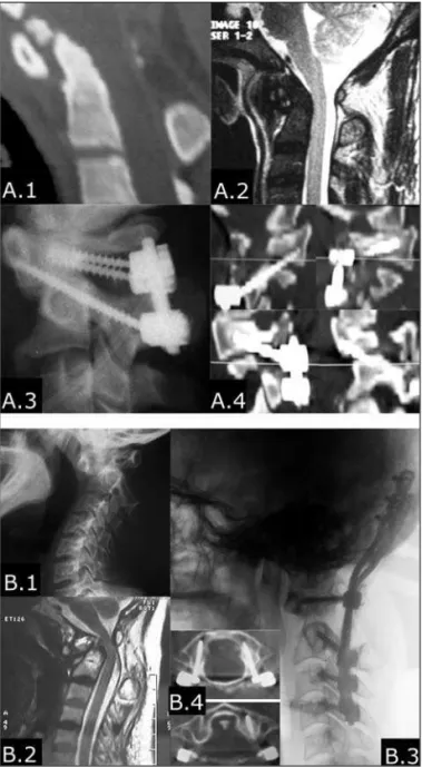
Fig 3. A.1 and A.2: C-spine sagital reformatted CT scan and MRI scan showing an os odontoideum associated with C1-C2 subluxa-tion and spinal cord compression; A.3: Postoperative C-spine lat-eral X-ray showing a three-point construct with C1-C2 transartic-ular screws plus C1 lateral mass screws; A.4: Postoperative CT scan showing C1-C2 transarticular screws plus C1 lateral mass screws. B.1: Lateral C-spine x-ray demonstrating a severe C1-C2 subluxa-tion with marked erosion of the dens and increased atlanto-dens interval. B.2: T2-weighed MRI scan showing dens erosion, marked-ly increased atlanto-dens interval and spinal cord compression; B.3: Postoperative lateral C-spine x-ray showing segmental occipital-C4 fixation. B.4: CT scan showing optimal placement of C1 lateral mass screws and restoration of a normal atlanto-dens interval.
modified Brooks quite often did not provide suffi-cient rigidity and as a result nonunions rates were high6,8-10. More recently, studies on biomechanics of
the atlantoaxial joint have demonstrated that its kine-matics is indeed complex and there is intervertebral coupled motion at the C1-C2 joints11. For instance,
when there is right rotation of the atlas, there are coupled left lateral bending and extension of the lat-eral masses11. The greatest degree of motion at the
atlantoaxial joints takes place with axial rotation, which has about 36-41.5 degrees of movement to each side11. Although wiring techniques restrict
flex-ion-extension, they allow considerable motion dur-ing axial rotation and benddur-ing1,12. In 1987, Magerl
introduced the technique of C1-C2 transarticular screws combined with a posterior wiring technique, which provided a three-point fixation of the C1-C2 complex3. This technique was later shown
biomecha-nically to prevent motion in all planes very efficient-ly1,2,12-14. Various authors subsequently demonstrated
the superiority of transarticular screws combined with posterior wiring when compared to posterior wiring alone in the treatment of C1-C2 instability4,6,9,10,15-17.
There are some drawbacks in the use of C1-C2 transarticular screws, though. The C1-C2 alignment has to be perfect prior to inserting the screws, there is the risk of injuring the vertebral artery, especially when it is high-riding or has an anomalous course, and the proper angle of the screws can not be achie-ved when the patient has a marked thoracic kypho-sis or is markedly obese. Harms subsequently describ-ed the technique of C1 lateral mass screws combindescrib-ed with C2 pedicle screws as a way to immobilize the C1-C2 complex5. The efficacy of this technique in
achieving high fusion rates and good outcomes was clearly demonstrated5.The main advantages are that
it can be used in patients with a rigid neck, in those patients who have an anomalous course of the verte-bral artery or when the verteverte-bral artery is high-rid-ing. Furthermore, the C1 and C2 screws can be placed before reduction is performed.
The technique of C1 lateral mass combined with C2 pedicle screws provides at least the same rigidity as the C1-C2 transarticular screws combined with pos-terior wiring and superior stability when compared to wiring techniques alone1,12,13. Different
biomechan-ical studies have demonstrated that this type of con-struct provides not only immediate stability but and also rigidity in flexion-extension, lateral bending and axial rotation1,12,13.
The use of C1 lateral mass screws can also be par-ticularly useful when a multilevel segmented
instru-mentation is needed. Two of our patients had a mul-tilevel fusion in which C1 screws were placed as part of the construct. Both patients had rheumatoid arthri-tis. In patient 10, this was particularly useful: the pla-cement of the C1 and C2 screws was done after a few occipital screws and the rods were in place, which helped achieving the final reduction by pulling C1 backwards and pushing C2 anteriorly.
The suitability of the lateral mass to accept screws has been demonstrated either via posterior arch or lateral mass alone18-20. Moreover, the pullout strength
of the C1 lateral mass screws has been shown to be equivalent to the C2 pedicle screws18. We prefer
plac-ing C1 lateral mass screws with a startplac-ing point right on the posterior arch of the atlas, as suggested by Tan et al.20. We point some advantages that led this
technique to be our preferred method.
The posterior arch has considerable thickness to accept 3.5 mm screws20, the screw entry point can be
easily chosen20with minimal additional dissection,
there is no need to sever or manipulate the C2 root, the screws trajectory is longer and the C1 screw head can be perfectly aligned with the C2 screw head. Our preferred entry point is usually midway between the foramen transversarium and the posterior medial edge of the C1 lateral mass.
We usually aim the anterior arch and angle the K- wire 5-10 degrees medially, using continuous flu-oroscopy. With this technique, there were no instan-ces of vertebral, dural or nerve root injury. In two pa-tients we were not able to place screws directly on the posterior arch due to its small size and an entry point below the arch was used.
Although choosing C1 lateral mass screws com-bined with C2 pedicle screws can be a good alterna-tive when transarticular screws are not feasible, the placement of C2 pedicle screws can also injure the vertebral artery, especially when it has a more medi-al course19. When this is the case, we prefer placing
a shorter screw (pars screw) that stops just posterior to the vertebral artery foramen.
The idea of building a construct that uses a three-point fixation comes from the principles of biome-chanics that the more points of fixation one uses, the more rigid and stable the construct is2. Several
These techniques have also been studied biomechan-ically and the C1-C2 transarticular screws combined with posterior wiring and the C1-C2 transarticular screws combined with a C1 claw showed the small-est overall range of motion and neutral zone1. The
C2 screws plus a C1 claw construct had larger values of range of motion and neutral zone for axial rota-tion, flexion-extension and lateral bending1.
Our idea of building a construct using C1-C2 trans-articular screws and C1 lateral mass screws also comes from these principles of a three-point fixation sys-tem. The particular anatomy of the C1 lateral mass, with its unique configuration (high and wide), allows placement of two independent screws on the same lateral mass, as we have done in some patients. The transarticular screw purchases the lateral mass at its anterior-inferior portion while the C1 screw purchas-es the middle portion of the lateral mass. The rods connecting the two screws establish a posterior ten-sion band and the addition of a cross-link adds sig-nificant rotational and axial stability. Although we have not done any biomechanical study, we can infer that this type of construct provides at least the same stability provided by the C1 lateral mass screws com-bined with C2 pedicle screws and at least the same stability conferred by C1-C2 transarticular screws alone.
Although some may argue that the transarticu-lar screws combined with a wiring technique provide an excellent three-point fixation technique1,2,12,14, the
passage of sublaminar wires is not without haz-ards10,17. This might be especially true for those
pa-tients in which there is a non-reducible C1-C2 sub-luxation and/or reduced space available for the cord. Several authors have described worsening of a pre-existing myelopathy as a complication of passing sub-laminar wires, particularly in patients with rheuma-toid arthritis and/or os odonrheuma-toideum6,10. For that
rea-son, they recommended transarticular screws when stabilizing the C1-C2 complex in the presence of an os odontoideum, avoiding posterior wiring6.
We used this new technique of C1-C2 transartic-ular screws combined with C1 lateral mass screws in three patients. The indications to use this type of con-struct were the combinations of conditions that increase the risk of nonunion combined with a nonre-ducible C1-C2 subluxation and a small space avail-able for the cord. Additionally, it was desiravail-able to build a construct as rigid as possible so as to avoid postoperative halo bracing in these fragile patients.
In conclusion, C1 lateral mass screws are a safe
method of obtaining segmental fixation of the atlas. They can be especially valuable when a multilevel segmental construct that includes the occipitocervi-cal junction or subaxial cervioccipitocervi-cal spine is desired. The use of C1-C2 transarticular screws combined with C1 lateral mass screws proved to be a feasible and effi-cacious method of three-point fixation of the C1-C2 complex. It can be particularly useful in those cases when the C1 posterior arch is fractured, when a C1 laminectomy is required, or when the surgeon wish-es to place transarticular screws and do a three-point fixation but avoid the risks of passing sublaminar wires.
REFERENCES
1. Richter M, Schmidt R, Claes L, Puhl W, Wilke HJ. Posterior atlantoax-ial fixation: biomechanical in vitro comparison of six different tech-niques. Spine 2002;27:1724-1732.
2. Naderi ST, Crawford, NR, Song, GS; Sonntag, VK, Dickman, CA. Bio-mechanical comparison of C1-C2 posterior fixations: cable, graft, and screw combinations. Spine 1998;23:1946-1955.
3. Magerl F, Seeman P. Stable posterior fusion of the atlas and axis by transarticular screw fixation. In Kehr P, Weidner A (eds). Cervical spine. Strassbourg, Wien, New York: Springer-Verlag, 1985:322-327. 4. Dickman CA, Sonntag VK. Surgical management of atlantoaxial
nonunions. J Neurosurg 1995;83:248-253.
5. Harms J, Melcher RP. Posterior C1-C2 fusion with polyaxial screw and rod fixation. Spine 2001;26:2467-2471.
6. Coyne TJ, Fehlings MG, Wallace MC, Bernstein M, Tator CH. C1-C2 Posterior cervical fusion: long-term evaluation of results and efficacy. Neurosurgery 1995;37:688-693.
7. Ebraheim NA, Xu R, Ahmad M, Heck B. The quantitative anatomy of the vertebral artery groove of the atlas. Spine 1998;23:320-323. 8. Dickman CA, Crawford NR, Paramore CG. Biomechanical
character-istics of C1-2 cable fixations. J Neurosurg 1996;85:316-322.
9. Taggard DA, Kraut MA, Clark CR, Traynelis VC. Case-control study comparing the efficacy of surgical techniques for C1-C2 arthrodesis. J Spinal Disord Tech 2004;17:189-194.
10. Reilly TM, Sasso RC, Hall PV. Atlantoaxial stabilization: clinical com-parison of posterior cervical wiring technique with transarticular screw fixation. J Spinal Disord Tech 2003;16:248-253.
11. Ishii T, Mukai Y, Hosono N, et al. Kinematics of the subaxial cervical spine in rotation in vivo three-dimensional analysis. Spine 2004;29:2826-2831.
12. Melcher RP, Puttlitz CM, Kleinstueck FS, Lotz JC, Harms J, Bradford DS. Biomechanical testing of posterior atlantoaxial fixation techniques. Spine 2002;27:2435-2440.
13. Kim SM, Lim TJ, Paterno J, et al. Biomechanical comparison of anteri-or and posterianteri-or stabilization methods in atlantoaxial instability. J Neurosurg 2004;100:277-283.
14. Mitchell, TC, Sadasivan KK, Ogden AL, et al. Biomechanical study of atlantoaxial arthrodesis: transarticular screw fixation versus modified brooks posterior wiring. J Orthop Trauma 1999;13:483-489.
15. Haid RW Jr, Subach BR, McLaughlin MR, Rodts GE Jr, Wahlig JB Jr. C1-C2 transarticular screw fixation for atlantoaxial instability: a 6-year experience. Neurosurgery 2001;49:65-68.
16. Dickman CA, Sonntag VK. Posterior C1-C2 transarticular screw fixa-tion for atlantoaxial arthrodesis. Neurosurgery 1998;43:275-280. 17. Eleraky MA, Masferrer R, Sonntag VK. Posterior atlantoaxial facet
screw fixation in rheumatoid arthritis. J Neurosurg 1998; 89:8-12. 18. Hong X, Dong Y, Yunbing C, Qingshui Y, Shizheng Z, Jingfa L. Posterior
screw placement on the lateral mass of atlas: an anatomic study. Spine 2004;29:500-503.
19. Resnick DK, Lapsiwala S, Trost GR. Anatomic suitability of the C1-C2 complex for pedicle screw fixation. Spine 2002; 27:1494-1498. 20. Tan M, Wang H, Wang Y, et al. Morphometric evaluation of screw