Artigo
*e-mail: [email protected]
THEORETICAL INVESTIGATION OF ELECTRONIC EXCITATION TRANSFER BETWEEN CHLOROPHYLLS IN LIGHT-HARVESTING ANTENNA OF PHOTOSYSTEM II USING QUANTUM COMPUTERS
Maryam Dehestani*
Department of Chemistry, Shahid Bahonar University of Kerman, Kerman / Department of Materials Science and Engineering, International Center for Science, High Technology & Environmental Sciences, Kerman, Iran
Somaie Shojaei
Department of Chemistry, Payame Noor University of Kerman, Kerman, Iran Azita Khosravan
Department of Materials Science and Engineering, International Center for Science, High Technology & Environmental Sciences, Kerman, Iran
Recebido em 13/2/12; aceito em 2/5/12; publicado na web em 14/8/12
The excitation energy transfer between chlorophylls in major and minor antenna complexes of photosystem II (PSII) was investigated using quantum Fourier transforms. These transforms have an important role in the efficiency of quantum algorithms of quantum computers. The equation 2n=N was used to make the connection between excitation energy transfers using quantum Fourier transform,
where n is the number of qubits required for simulation of transfers and N is the number of chlorophylls in the antenna complexes.
Keywords: major and minor antenna of photosystem-II light-harvesting complex II (PSII-LHII) supercomplex; quantum Fourier transform; quantum gates.
INTRODUCTION
In higher plants, photosystem II-light-harvesting complex II (PSII-LHCII) in the thylakoid membranes is a supercomplex containing PSII surrounded by the light harvesting complex which includes the major LHCII proteins and three minor monomeric LHC proteins, CP29, CP26 and CP24.1 The supercomplex collects light energy, converts it into electro-chemical energy and drives electron transfer from water to plastoquinone. The reaction center (RC) is at the center of this complex.2
The major LHCII proteins are composed of three chlorophyll a/b binding proteins including LHCII Type I, II and III, encoded by Lhcb1, Lhcb2 and Lhcb3 genes, respectively.3 The X-ray crystal structure of the major antenna LHCII proteins in spinach (higher plants) at 2.72 A resolution revealed that these proteins form tri-mers. Each monomer LHCII polypeptide has been identified as 14 chlorophylls, 2 luteins and one neoxantin. These 14 chlorophylls (8 Chla and 6 Chlb) are vertically oriented into two layers lying close to the stromal or luminal surface. The eight chlorophylls (5 Chla and 3 Chlb) are located in the layer close to the stromal sur-face. The remaining six chlorophylls (3 Chla and 3 Chlb), which form two separate clusters including 4 chlorophylls (3 Chlb and 1 Chla) and a Chla-Chla dimer, are located in the layer close to the luminal surface.4
The minor antennae CP29, CP26 and CP24 in green plants lie at the interface between the core antenna and the major antenna (LHCII) of PSII-LHCII supercomplex.2 These minor complexes, which toge-ther bind about 15% of total PSII chlorophyll, appear to be involved in the dissipation of the chlorophyll excitation energy required to stop overexcitation and photoinhibition of PSII.5,6
Since at the level of single atoms and photons, quantum effects are significant, classical computation essentially becomes insufficient. New methods of computation, for example, quantum computations, have become possible. The basic concepts of quantum mechanics computation were formulated more than 20 years ago.7,8 The internal
state of a quantum computer can be changed by a series of unitary operations referred to as the quantum algorithm. The quantum Fourier transform is an essential subroutine in complicated quantum algori-thms such as factoring of large numbers,9 and simulating quantum systems.10 The quantum Fourier transform has been studied extensive-ly11 and has also been applied in nuclear magnetic resonance (NMR) and in many basic and important algorithms of quantum computers such as Shor’s Factoring Algorithm.12
Physicists believe that all aspects of the world around us can ultimately be explained using quantum mechanics.13 In this concept, a light harvesting antenna is a quantum mechanical particle system composed of a large number of atoms. The aim of the present paper was to simulate the excitation transition that arises from photon absorption in each of light harvesting complexes of major (LHCII) and minor antennae (CP29, CP29 and CP24) of PSII with quantum computers. In this study, the relationship between quantum computers and the above-mentioned light harvesting complexes is established with quantum Fourier transforms (QFT) for the first time. After studying energy transfer in each of the light harvesting complexes with QFT, calculator quantum circuits of these transforms, which in fact are representative of existing quantum computers, in both major and minor antenna complexes are drawn. These circuits simulate a quantum computer by making use of Hadamard, rotation and swap gates with regard to the number of qubits required for QFT.
GENERAL CONSIDERATIONS
The quantum Fourier transform
(1)
Correspondingly, the discrete quantum Fourier transform on an arthonormal basis |0〉, … , |N – 1〉 is a unitary transformation which is defined by
(2)
It suffices to take N = 2n, with n as an integer, and the basis |0〉, … ,|2n – 1〉 is the computational basis for an n-qubit quantum computer. It is preferable to write the state |j〉 using the binary re-presentation j = j1 j2…jn. More formally
j = j12n-1 + j22n-2 + … + jn20 (3) For simplicity, the quantum Fourier transform can be rewritten as the following useful product representation:
(4) where
(5) and jl (l = 1, 2, …, n) is equal to 0 or 1.
As explained later this representation allows construction of an efficient quantum circuit for the Fourier transform.14
Quantum gates
The internal state of the quantum computer is changed by quantum gates. A quantum gate is a sequence of unitary operations, the so-called quantum algorithm. In the first step, we introduce the Hadamard, ro-tational and swap gates which are useful in quantum algorithms. The Fourier transformations can be performed very efficiently by these gates.
The Hadamard gate which sets one qubit in superposition is a single-qubit gate defined by:
(6)
A symbolic representation of the Hadamard gate is given in Figure 1a.
The Rk gate denotes the single-qubit phase-shift operation by a phase 2π/2k on qubit k.
(7)
A symbolic representation of Rk is given in Figure 1b. This gate is depends on whether qubit k is 0 or 1.
The swap gate interchanges two qubit and a graphical represen-tation of this gate is shown in Figure 1c.
Efficient circuits for the quantum Fourier transform
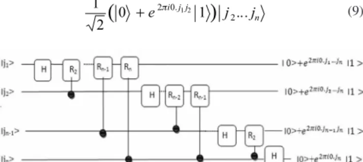
To construct the quantum circuit that performs QFT on an n--qubit quantum compute,r a specific sequence of the H and Rk gates is applied. The efficient circuit for the quantum Fourier transform is shown in Figure 2. The blocks labeled H perform a Hadamard trans-form, and the other blocks perform a controlled phase shift by the angle indicated. The series of swap gates that interchange the output qubits is not shown in the circuit. Consider what happens when the state |j1… jn〉 is input. The Hadamard gate which sets the first qubit
in superposition is applied in the first step.
(8)
where e2πi0.j1 = +1 when j
1 = 0, and is –1 otherwise. In the se-cond step, a unitary controlled-R2 gate is applied and produces t he state
(9)
We carry on applying the controlled-R3, R4 through Rn gates, each of which adds an extra qubit to the phase of co-efficient of the first | 1〉. Finally, this gives the state:
(10)
Next, a similar procedure is carried out on the second qubit. The Hadamard gate is applied to the second qubit:
(11)
and the controlled-R2 through Rn-1 gates yield the state:
(12) Continuing in this manner for each qubit gives the final state:
(13)
The relationship between quantum computers and light harvesting complexes of PSII
Excitation transition resulting from photon absorption in each of light harvesting complexes of major (LHCII) and minor antennas (CP29, CP29 and CP24) of PSII, could be simulated with quantum computers. The relationship between quantum computers and the light harvesting complexes is established with QFT.
Figure 1. Graphical representation of some of the basic gates used in quantum
computation; (a) Hadamard gate; (b) rotational (Rk) gate; (c) swap gate
Figure 2. Efficient circuit for the quantum Fourier transform. This circuit is
The relationship between electron excitation transfer in a LHCIImonomer and QFT
LHCII is a major antenna and has an important role in effective absorption of light energy. The configuration and number of chloro-phyll are different in both luminal and stromal near-to-surface layers of membrane. Since the number of chlorophylls is an important parameter in determination of qubits in QFT, simulation of excita-tion transfer between chlorophylls in these two surfaces is studied individually with QFT.
In order to determine the relationship between the number ofchlorophylls with QFT, the 2n = N equation is used. In this equa-tion, n represents the number of required qubits for simulation of transfers with QFT and N represents the number of chlorophylls and also indicates the number of states or the number of the com-putational basic set.
The total number of chlorophylls in the monomer luminal surface is six molecules. These chlorophylls are configured in two individual clusters with 2 and 4 molecules of chlorophylls, respectivelly. Since the number of chlorophylls is different in this surface, these two clusters are simulated with QFT individually.
The relationship between binary cluster of luminal surface of LHCII monomer and QFT
In the binary cluster of the luminal surface, by substituting the number of chlorophylls (N = 2) using the equation 2n = N we obtain the number of qubits (n) which is equal to 1. The transfer energy be-tween chlorophylls of the binary cluster of LHCII monomer luminal surface can then be simulated with a single-qubit Fourier transform. In order to achieve this, the equations outlined in the section above are rewritten and executive quantum circuits of these transforms drawn.
Rewriting equations for single-qubit Fourier transform
For single-qubit Fourier transform, basic set includes two mem-bers {|0>, |1>}, thus the state used is |j> = |j1>, which by substituting in Equation 2 gives Equation 14:
(14)
j1/2 = 0.j1, is replaced and Equation 14 becomes Equation 15:
(15)
Equation 15 is now executing a single-qubit Fourier transform.
Drawing executive quantum circuits of single-qubit Fourier transform
The executive circuit diagram of the single-qubit Fourier trans-form is shown in Figure 3. A two-member basis set (| 0〉 and | 1〉) is the input and is the output. This circuit has only one Hadamard gate. Table 1 shows the output of single-qubit Fourier transform for the states | 0〉 and | 1〉.
Matrix representation of single-qubit Fourier transforms
Fourier transforms can be shown in matrix notation. The number of columns and rows of the matrix is given by 2n, where n represents number of qubits. Representing the operator of Fourier transform as F, the 2×2 matrix elements F can be rewritten as follows:
(16)
Therefore, the single-qubit Fourier transform matrix F can be written as:
(17)
where ω = eiπ.
The relationship between quartet cluster of luminal surface of LHCII monomer and QFT
In this cluster, by substituting the number of chlorophylls (N = 4) in the equation 2n = N, we then obtain the number of qubits (n) which is equal to 2. Energy transfer between chlorophylls of the quartet cluster of the LHCII monomer luminal surface can be simulated with a two-qubit Fourier transform. In order to achieve this, the equations outlined in the section above are rewritten and executive quantum circuits of these transforms then drawn.
Rewriting equations for two-qubit transform
For two-qubit Fourier transform, the basic set includes four mem-bers {| 00〉, | 01〉, | 10〉, | 11〉}, where state used is |j〉 = |j1j2〉 which by substituting in Equation 3, gives j = 2j1+j2. Table 2 shows all states |j〉. The state |j〉 in terms of qubits | 0〉 and | 1〉 can thus be expressed as:
(18) Substituting Equation 3 into Equation 18 and comparing the results with Equation 5 gives the state vector of the system in the form of Equation 19:
(19)
Equation 19 is executing two-qubit Fourier transform.
Figure 3. General representation of executive circuit of single-qubit Fourier
transform. Value 0.j1 could be shown in form of j1/2
Table 1. Representations of single-qubit Fourier transform
|j1〉 Output of first qubit
| 0〉
| 1〉
Table 2. States of j for quartet cluster of lumenial surface of LHCII monomer
j1 j2 j = 2j1 + j2 |j〉 = |j1 j2〉
0 0 0 | 0 〉 = | 00 〉
0 1 1 | 1 〉 = | 01 〉
1 0 2 | 2 〉 = | 10 〉
Drawing executive quantum circuits of two-qubit Fourier transform
The circuit that represents two-qubit Fourier transform is shown in Figure 4.
To construct the quantum circuit that performs two-qubit QFT, a specific sequence of the Hadamard and R2 rotation gates is applied. The input state is the computational base state |j1j2〉. For the first sequence the Hadamard and R2 rotation gates are applied on the first qubit. For the second sequence, the Hadamard gate is applied on the second qubit. Applying the Hadamard gate to the first qubit produces the state:
(20)
Applying the R2 rotation gate produces the state:
(21)
Applying the Hadamard gate to the second qubit produces the state:
(22)
Comparing the Fourier transform output represented by Equation 19 with circuit output Equation 22, we see that the position of qubits in these equations is inverted. The swap operation omitted from Figure 4 is then used to reverse the order of the qubits.
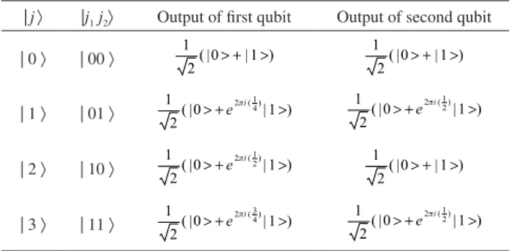
Table 3 shows the output of two-qubit Fourier transform for the four states | 00〉, | 01〉, | 10〉 and | 11〉.
Matrix representation of two-qubit Fourier transform
The two-qubit Fourier transform operator F can be written as a 4×4 matrix which has the following form:
(23)
The matrix elements may be written out explicitly, using powers of ω as shown in Equation 24:
(24)
where ωn = e2nπi/4.
Investigation of excitation energy transfer between chlorophylls of stromal surface of a LHCII monomer using QFT
The total number of chlorophylls in the stromal surface of the LHCII monomer is equal to eight molecules, which are configured in an octet cluster. Substitution of N = 8 in the equation 2n = N gives a value of n of 3. Thus transfer energy among chlorophylls of octet cluster of the LHCΙΙ monomer stromal surface can be simulated with a three-qubit Fourier transform. In order to achieve this, the equations outlined in the section above are rewritten and executive quantum circuits of this transform then drawn.
Rewriting equations for three-qubit transform for three-qubit Fourier transform
The basic set includes eight members {| 000〉, | 001〉, | 010〉, | 011〉, | 100〉, | 101〉, | 110〉, | 111〉} thus state used is |j〉 = |j1j2j3〉 which by substituting in Equation 3, gives j = 4j1 + 2j2 + j3〉. Table 4 shows the all states |j〉. The state |j〉 in terms of qubits | 0〉 and | 1〉 can be expressed as:
(25)
Substituting Equation 3 into Equation 25 and comparing the results with Equation 5 gives the state vector of the system as shown in Equation 26:
(26)
Figure 4. General representation of an executive circuit of two-qubit Fourier
transform. Values 0.j2 and 0.j1j2 could be shown in form of (j2/2) and (j1/2+j2/4),
respectively
Table 3. Representations of two-qubit Fourier transform
|j〉 |j1 j2〉 Output of first qubit Output of second qubit
| 0 〉 | 00 〉
| 1 〉 | 01 〉
| 2 〉 | 10 〉
| 3 〉 | 11 〉
Table 4. States of j for octet cluster of steromal surface of monomer LHCII
j1 j2 j3 j = 4j1 + 2j2 + j3 |j〉 = |j1 j2j3〉
0 0 0 0 | 0 〉 = | 000 〉
0 0 1 1 | 1 〉 = | 001 〉
0 1 0 2 | 2 〉 = | 010 〉
0 1 1 3 | 3 〉 = | 011 〉
1 0 0 4 | 4 〉 = | 100 〉
1 0 1 5 | 5 〉 = | 101 〉
1 1 0 6 | 6 〉 = | 110 〉
Equation 26 is executing three-qubit Fourier transform.
Drawing executive quantum circuits of three- qubit Fourier transform
The circuit that represents three-qubit Fourier transform is shown in Figure 5.
To construct the quantum circuit that performs three-qubit QFT, a specific sequence of the Hadamard and R2 rotation gates is applied. The input state is the computational base state |j1j2j3〉. For the first sequence, the Hadamard, R2 and R3 rotation gates are applied on the first qubit. For the second sequence, the Hadamard and R2 rotation gates are applied on the second qubit. For the third sequence, the Hadamard gate is applied on the third qubit. Applying the Hadamard gate to the first qubit produces the state:
(27)
Applying the R2 and R3 rotation gates produce the state:
(28)
Applying the Hadamard gate and then R2 rotation gate to the second qubit produce the state:
(29)
Applying the Hadamard gate to the third qubit produces:
(30)
Comparing Fourier transform represented as output Equation 26 with circuit output Equation 30 shows that the position of qubits in these equations is inverted. One swap gate omitted from Figure 5 is then used to reverse the order of the qubits.
Table 5 shows the output of three-qubit Fourier transform for the eight states | 000〉, | 001〉, | 010〉, | 100〉, | 011〉, | 101〉, | 110〉, and | 111〉.
Matrix representation of three-qubit Fourier transform
The three-qubit Fourier transform operator F can be written as an 8×8 matrix which has the following form:
(31)
The matrix elements may be written out explicitly, using powers of ω as shown in Equation 32:
Figure 5. General representation of an executive circuit of three-qubit
Fou-rier transform. Values 0.j3, 0.j2j3 and 0.j1j2j3 could be shown in form of (j3/2),
(j2/2+j3/4) and (j1/2+j2/2+j3/8), respectively
Table 5.Representations of three-qubit Fourier transform
|j〉 |j1 j2j3〉 Output of first qubit Output of second qubit Output of third qubit
| 0 〉 | 000 〉
| 1 〉 | 001 〉
| 2 〉 | 010 〉
| 3 〉 | 011 〉
| 4 〉 | 100 〉
| 5 〉 | 101 〉
| 6 〉 | 110 〉
Table 6. Representation of relationship among the number of qubits and chlorophylls with number of gates in the major and minor complexes of PSII
Minor antenna Major antenna
CP24 CP26 CP29 LHCII
Steromal surface Lumenial surface
10 9 8 8 4 2 The number of Chl (N)
3 3 3 3 2 1 The number of qubit (n)
3 3 3 3 2 1 The number of H gates
2 2 2 2 1 0 The number of R2 gates
1 1 1 1 0 0 The number of R3 gates
1 1 1 1 1 0 The number of swap gates
(32)
which ωn = e2nπi/8.
The relationship between electron excitation transfer in minor antenna monomers CP24, CP26, CP29 with QFT
Minor antenna of Photosystem II consists of 3 monomers CP29, CP26 and CP24 whose number of chlorophylls is 8, 9 and 10 molecules, respectively. Substitution of N = 8, 9, and 10 in the equation 2n = N gives n values of 3, 3.17, and 3.32, respectively. For good approximation, excitation transfer among chlorophylls can be simulated in each of the monomers CP24, CP26 and CP29 with a three-qubit Fourier transform. Likewise, the executive quantum circuits and matrix representation could be applied for simulation of electron excitation transfer in minor antenna monomers CP24, CP26, CP29 using three-qubit Fourier transform (Table 6).
CONCLUSIONS
Quantum computers exist in nature. Photosynthesis is one exam-ple in which a quantum computer component may play a role in the classical world of complex biological systems. Biological systems represent an untapped resource for thinking about the design and ope-ration of quantum computers and expanding our current conception of what defines a ‘quantum computer’ in nature.
In this report excitation energy transfer among chlorophylls of light-harvesting major complexes (LHCII) and light-harvesting minor complexes (CP24, CP26 and CP29) of Photosystem II was studied for the first time using quantum computers. The results have shown that excitation energy transfer among chlorophylls of these antenna systems can be simulated with quantum Fourier transform.
In order to establish a relationship between excitation energy transfer resulting from photon absorption by chlorophyll molecules of
minor and major antenna with quantum Fourier transforms, equation 2n = N has been used. In this equation, n represents the number of required qubits for the simulation with QFT and N shows the number of states created with n-qubit Fourier transform which is equal to the number of chlorophylls in the studied antenna system.
Since the number of chlorophylls is a major factor for the de-termination of the number of required qubits in the simulation with QFT, transfer in each complex was studied individually.
The electron excitation transfer in binary and quartet clusters of the luminal surface of the LHCII monomer was simulated using single and two-qubit Fourier transforms, respectively. The three-qubit Fourier transform was applied to simulate the electron excitation transfer in the octet cluster of the luminal surface of the LHCII monomer and CP26, CP24, and CP29 monomers. Table 6 provides a brief summary of our results. Simulator quantum circuits of these transforms in each part have been drawn using Hadamard, Rn rotation and swap quantum gates.
REFERENCES
1. Wentwork, M.; Ruban, A. V.; Horton, P.; J. Biol. Chem. 2003, 278, 24845.
2. Minagawa, J.; Takahashi, Y.; Phtosynth. Res. 2004, 82, 241.
3. Jansson, S.; Pichersky, E.; Bassi, R.; Green, B. R.; Ikeuchi, M.; Melis, A.; Simpson D. J.; Spangfort M.; Staehelin, L. A.; Thornber, J. P.; Plants Mol. Biol. Rep. 1992, 10, 242.
4. Liu, Z.; Yan, H.; Wang, K.; Kuang, T.; Zhang, J.; Gul, L.; An, X.; Chang, W.; Nature 2004, 428, 287.
5. Dainese, P.; Bassi, R.; J. Biol. Chem. 1991, 266, 8136.
6. Bassi, R.; Sandona, D.; Croce, R.; Physiol. Plan. 1997, 100, 769. 7. Benioff, P.; J. Stat. Phys. 1980, 22, 563.
8. Feynman, R. P.; Int. J. Theor. Phys. 1982, 21, 467. 9. Grover, L.; ACM Sym. Theory Comp. 1996, 1, 212. 10. Lloyd, S.; Science 1996, 273, 1073.
11. Pittenger, A. O.; An Introduction to Quantum Computing Algorithms, 1st
ed., Birkhauser Boston: Cambridge, 1999.
12. Weinstein, Y. S.; Pravia, M. A.; Fortunato, E. M.; Lloyd, S.; Cory, D. G.; Phys. Rev. Lett. 2001, 86, 1889.
13. Karafyllidis, I. G.; Quant. Inf. Proc. 2003, 2, 271.