ISSN 0104-6632 Printed in Brazil
www.abeq.org.br/bjche
Vol. 30, No. 03, pp. 627 - 641, July - September, 2013
Brazilian Journal
of Chemical
Engineering
THE EFFECT OF THE INTRODUCTION OF
AN EXIT TUBE ON THE SEPARATION
EFFICIENCY IN A CYCLONE
J. Cernecky
1and K. Plandorova
21Technical University in Zvolen, Faculty of Environmental and Manufacturing Technology,
Department of Environmental Technology, T. G. Masaryka 24, 960 53 Zvolen, Slovakia, Europe. E-mail: [email protected]
2SIGMA SLOVAKIA, Zvolenska cesta 14 / 1769 974 01 Banska Bystrica, Slovakia, Europe.
(Submitted: February 22, 2012 ; Revised: August 14, 2012 ; Accepted: August 25, 2012)
Abstract - The paper shows the analysis of the effect of introduction of an exit tube into the cylindrical part of a cyclone on the flow velocity, pressure losses and, above all, the separation efficiency. We made measurements and carried out CFD simulations for three levels of the exit tube introduction. The ratios of the depth of the exit tube introduction to the cyclone diameter (Hp/D) were 0.4, 0.475 and 0.89 at three velocity settings of 8 m.s-1, 13 m.s-1 and 15 m.s-1. The Reynolds Stress Model (RSM), which was compatible with the experimental results, was used for numerical solutions. The efficiency of cyclone separation was explored on a sample of oak sawdust. The efficiency of cyclone separation increased with the geometric size of the particles, the inlet velocity and a deeper introduction of the exit tube.
Keywords: Cyclone; Separation; Computational fluid dynamics; Oak sawdust.
INTRODUCTION
Cyclones are technical devices which are used for separating loose matter from carrier gas with the utilization of gravitational, inertial and centrifugal forces. A simple construction, possible operating reliability, low investment and operating costs and low energy consumption are the basic qualitative aspects of the cyclone. Low separation of soft particles, abrasive effects and adhesive power of particles are among to the disadvantages. The total cyclone efficiency is influenced by factors such as the flow rate of a heterogeneous mixture through the cyclone, the properties and concentration of loose matter, cyclone design and its setting, total separation, fractional separation, cyclone resistance, deterioration and other factors. The heterogeneous mixture enters the cylindrical part of a separator and, after that, it is put into a downward rotary movement
The works of Lapple (1951) and Barth (1956) are considered to be the first studies dealing with cyclone models. The studies were simple and provided acceptable results with a limited range of parameters. Later, those theories were improved by Smith (1962) and Muschelknautz (1970). In their theories they considered more parameters such as surface roughness, area of distribution of particles, shape and size of particles, pressure losses and others. The efficiency of vortex separators depends on the regime, which is also influenced, apart from the already mentioned parameters, by inlet velocity, temperature and viscosity, which are introduced in the work of Avci and Karagoz (2003). This work investigated the cyclone flow patterns introducing different shapes and diameters of exit tube simulated at diverse flow rates. Lim et al. (2004) examined experimentally the effect of vortex finder shape on the characteristics of the collection efficiency at different flow rates. Elsayed et al. (2010) evaluated the flow patterns and performance of a cyclone with different vortex finder diameters to examine the effect of the vortex finder diameter on the performance and velocity profile. In the experimen-tal work of Hoffman et al. (1995) it was proved that the inlet velocity has a significant influence on the length of turbulence depending on cyclone geometric dimensions. The paper of Lidén and Gudmundsson (1996) described the use of semi-empirical polyhedra for separation efficiency depending on the operating conditions and cyclone dimensions. The length of turbulence in the cyclone increased with increasing inlet velocity. In the work of Martignoni et al. (2007), the impact of cyclone geometry was studied by means of creating a symmetrical double inlet and a cyclone model with a spiral outlet compared with a common cyclone with a tangential inlet. It was verified that the total separation efficiency increases with decreasing pressure drop in both cyclone shapes, but in a cyclone with shaped symmetrical inlets a bigger pressure drop was recorded than in the cyclone with the spiral outlet. The results of the experimental study of Kim, Lee and Kuhlman (2001) provide information about the efficiency of particle separation for a modified inner surface of the body of cyclones with spiral, circumferential and vertical grooves. The estimation of separation efficiency dependent on the concentration of particles in axial flow in a cyclone dust collector was published by Ogawa (1999). Under the centrifugal force solid particles slide along the cone surface and fall into a dust hopper, where some particles are trapped and some are blown away by secondary flow back to the cyclone body.
A literature survey showed that the vortex length can be important for predicting the separation efficiency, especially in short cyclones, but for longer cyclones the turbulence does not have to reach the cone top. If the length of a cyclonic cylinder increases, the separation efficiency in-creases to a certain value and then it begins to decrease; it is also similar in an overflow pipe. By lengthening the height of the cyclonic cylinder or by shortening the length of the overflow pipe we can lessen the pressure drop to a certain extent (Zhu and Lee, 1999). The definition and composition of the pressure drop in the cyclone were analysed in the paper of Chen and Shi (2006). The pressure drop in the cyclone includes spreading losses at the inlet into the cyclone and outlet spinning losses caused by the friction near the walls of the cyclone and the dynamic energy of the diffused gas in the overflow pipe. The surface resistance or losses caused by friction have a substantial influence on the vortex length; with decreasing surface resistivity the length of turbulence in the cyclone increases. Numerical studies of separable properties of different concentra-tions of particles in the cyclone at the inlet were investigated in the paper of Oian et al. (2007). The effects of inlet concentration of particles on the tangential velocity, particle size, pressure drop and separation efficiency in the cyclone were deter-mined. The impacts of cone dimensions on the cyclone performance were examined in the study of Xiang et al. (2000).
The Effect of the Introduction of an Exit Tube on the Separation Efficiency in a Cyclone 629
described in the paper of Meier and Mori (1998). In this work, the CFD model was based on an Eulerian approach for both phases with the condition of a 3D symmetrical domain, the mathematical model was compiled for the utilization of the k-ε turbulent model.
The possibility of using CFD techniques enables one to make a proposal of more effective separation conditions without the need of conducting expensive experiments. Currently, CFD simulations have rela-tively wide application for relarela-tively precise mathe-matical approximation of flow, while the arduousness of its performance and time restraints in solving concrete physical problems must not be forgotten.
TURBULENT MODEL DESCRIPTION
The use of CFD (computational fluid dynamics) for numerical calculations of gas flow in the cyclone has increasingly been applied. Three models are usually used for the simulation in the cyclone: the
k-ε model, Algebraic Stress Model (ASM) and
Reynolds Stress Model (RSM). Wang et al. (2006)
found that the standard k-ε turbulence model is inadequate to simulate the flow with swirling motion because it leads to excessive turbulence viscosity and unrealistic tangential velocity. Therefore, the accu-racy of the numerical solution can be improved by using the Reynolds Stress Model (RSM), which was also utilized in this paper for the simulation of physical actions in the cyclone by using the FLUENT commercial program.
In turbulent flow, which is accompanied by pulsation and fluctuation, the total velocity equals the sum of the central and fluctuation components of velocity:
i i i
u = +u u ' . (1)
By substituting this expression into the equation of motion we get the averaged Navier-Stokes equations of motion in the form:
( )
( )
(
)
i i j
j
j j
i
j j i j
i i j
i j
u u u
t x
u u
u 2
x x x 3 x
p
g F u u ,
x x
∂ ρ + ∂ ρ
∂ ∂
⎛ ⎡ ∂ ⎤ ⎛ ∂ ⎞⎞
∂ ∂
=∂ ⎜⎜μ⎢∂ +∂ ⎥ ⎜− μ⎜ ∂ ⎟⎟⎟⎟
⎢ ⎥
⎣ ⎦ ⎝ ⎠
⎝ ⎠
∂ ∂ ′ ′
−∂ + ρ + +∂ −ρ
(2)
where ρ is the density, u is the mean velocity, x is the position, t is the time, p is the pressure, μ is the dynamic viscosity, u ui′ ′j is the Reynolds stress tensor, g is the acceleration of gravity and Fi is the external body force which arises due to the interaction with dispersed solid particles.
This equation of motion now represents the averaged velocity values (or main flow). Turbulence is represented by means of the “Reynolds stresses”
_____ i j
u u′ ′
ρ . FLUENT describes the effect of main flow and the Reynolds stresses by means of the above mentioned models. The Reynolds Stress Model includes the calculation of particular Reynolds stresses by means of a transport differential equation in the form:
(
)
( )
(
)
(
)
( )
( )
( )
( )
( )
i j i j k
k
ij
i j k kj i ki j i j
k k
ij
j i i j
i k i k
k k j i
ij ij
i i u k k
ij u u u u
u
t x
LTM C
p
u u u u u u u
x x
D
u u p u u
u u u u
x x x x
P
u u
2 S ,
x x ′ ′ ′ ′ ∂ ∂ + = ∂ ∂ ⎡ ′ ⎤ ∂ ′ ′ ′ ′ ′ ∂ ′ ′
−∂ ⎢ +ρ δ + δ − υ∂ ⎥
⎣ ⎦
⎡ ⎤
∂ ∂
⎡ ′ ′ ′ ′ ∂ ⎤ ′ ∂
−⎢ ∂ + ∂ ⎥+ ρ ∂⎢⎢ +∂ ⎥⎥
⎣ ⎦ ⎣ ⎦
Φ
⎡∂ ∂ ⎤
− υ⎢ ⎥+
∂ ∂
⎣ ⎦
ε
(3)
where the left two terms are the local time derivative of stress (LTM) and the convective transport term (Cij), respectively. The right five terms are: Dij is the stress diffusion term, Pij isthe shear production term, Фij is the pressure- strain term, εij is the dissipation term and Su is the source term.
For better expression, the individual members are approximated for the purpose of closing the set of simultaneous equations from this differential equa-tion. The Reynolds stresses are consequently substi-tuted into the equation of momentum transfer. Generally, the following equations are solved by using the RSM model:
6 transport equations in the form (3),
3 transport equations for the mean component of velocity,
transport equation for the rate of dissipation ε. Generally, this system solves 12 equations. In comparison with the previous models, a dispropor-tionally greater arduousness is placed on the numerical model (Launder et al., 1975).
The equation of motion of a small particle, including the effects of nonlinear drag and gravita-tional forces, is given by:
(
)
P
D p P
i
i i i
2
3 C Re du
u u g
dt 4d S
ν
= − + , (4)
P i
i
dx u
dt
= . (5)
where u is the velocity of the particle and xiP i is its position, d is particle diameter, S is the ratio of particle density to fluid density, gi is the acceleration of gravity and according to Raoufi et al. (2008) the drag coefficient CD is given as:
D P
24 C
Re
= , for ReP < 1, (6)
2/3
D P
P
24 1
C (1 Re )
Re 6
= + , for 1 < ReP < 400, (7)
where ReP is the particle Reynolds number defined as:
P
j j
P
d u u
Re = −
ν . (8)
CONDITIONS OF THE EXPERIMENT AND CFD SIMULATION
Figure 1 shows a designed cyclone model with a tangential inlet and Table 1 shows basic cyclone dimensions. The cyclone model is placed in an experimental overpressure system for the loose matter separation of diverse composition and concentration. This device was used for experimental purposes with an inlet concentration of particles of 0.01 kg. N-1.m-3. In terms of air flow it is an air-technical system where the transport air is drawn from the room to a pipe system and from the cyclone separator transported back to the ambient environment.
Figure 1: A cyclone model with the main dimensions Table 1: Basic dimensions of a cyclone model (mm)
D dp dk b1 h1 Hv Hk Hp Hc dm Hm
200 65 85 40 90 262 520 178 782 150 110
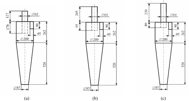
A set of measurements was carried out for three positions of introduction of an exit tube into the inner part of the cyclone at a barometric pressure of 1 025 hPa. The exit tube is in the shape of a cylinder with a length of 300 mm and was designed in a way so that it is possible to set the necessary depth of introduction of the tube in the cyclone. The first measurements were made at a ratio of Hp/D = 0.89, Figure 2 (a). The second measurements were performed at a ratio of Hp/D = 0.475, just below a bottom wall of the inlet cyclone pipeline. The third measurements were carried out at a ratio of Hp/D = 0.4, Figure 2 (c). A five-port dynamic probe clamped in a special holder was used for these measurements. The probe was calibrated on a calibration device before the measurements (Polansky and Stech, 2011). A sample of oak sawdust with a density of 670 kg.m-3 and dampness of 6.5% was used for finding out the cyclone separation efficiency.
The Effect of the Introduction of an Exit Tube on the Separation Efficiency in a Cyclone 631
13 m.s-1 and 15 m.s-1. Three types of CFD models were created. They represented three different examples of the introduction of an exit tube into the cylindrical part of the cyclone. Surfaces were covered with a hexagonal grid of tetra-hybrid type, Figure 3, which was converted to a grid of the poly-hedral type in the FLUENT program. A computa-tional domain for the variant of Hp/D = 0.4 comprises 79,393 CFD cells, for the variant of Hp/D = 0.475
it is 92,606 CFD cells and for Hp/D = 0.89 it is 111,661 CFD cells. Due the use of the polyhedral grid, which is of high quality, the grid optimization was not done during the computation.
In order to calculate the particle trajectories the following parameters of DPM (Discrete phase modelling) were set: the total flow rate – 0.0029 kg/s, the particle diameter – 1 mm, uniform particle distri-bution and particle material oak.
(a) (b) (c)
Figure 2: The introduction of an exit tube into the cylindrical part of the cyclone
RESULTS AND DISCUSSION
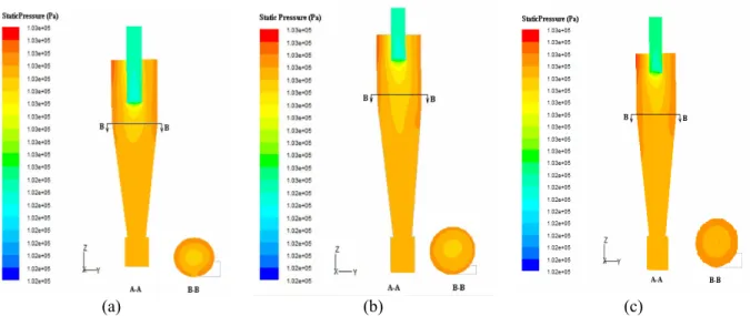
Figure 4 shows a static pressure at the velocity of 15 m.s-1 and three examples of the introduction of an exit tube. The B-B section represents an inlet plane for all measurements and its distance is 218 mm from the top part of the cyclone cap. The static pressure is the greatest along the inner wall of the lateral surface of the cyclone. On the cyclone axis the static pressure has lower values than on the walls and they are dependent on the vortex core and the introduction of an exit tube.
Figure 5 shows the relation between the dynamic pressure and the inlet gas velocity into the cyclone at Hp/D = 0.475.
With an increase in inlet velocity the dynamic pressure in the cyclone decreases. The experimental results coincide well with the numerical ones, although they are a bit higher.
Figure 6 shows the comparison of numerical and calculated tangential velocities in the cylindrical cyclone part at the inlet velocity of 15 m.s-1 to the cyclone. The results of the CFD simulation are in agreement with the calculated ones. The flow pattern indicates quasi-forced and free vortex flow. The turbulence on the cyclone axis agrees approximately with the axis of cyclone geometry just at this measurement.
The axial and tangential velocities were measured experimentally for three velocity settings at the ratios
(a) (b) (c)
Figure 4: Contours of static pressures at the velocity of 15 m.s-1 and at Hp/D of: (a) 0.89; (b) 0.475; (c) 0.4.
Figure 5: A comparison of numerical and calculated dynamic pressure.
The Effect of the Introduction of an Exit Tube on the Separation Efficiency in a Cyclone 633
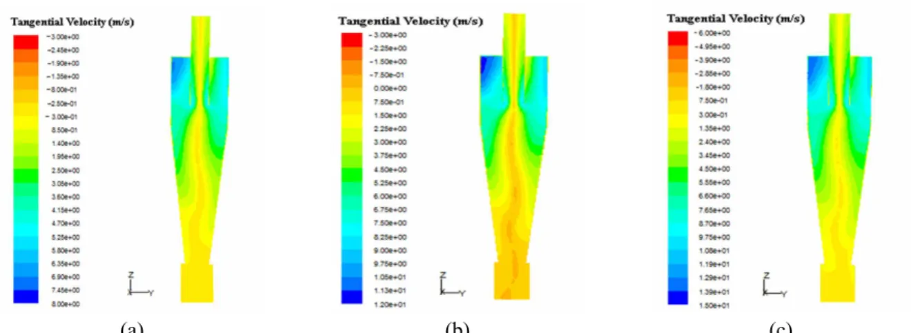
of Hp/D = 0.4, 0.475 and 0.89. Figures 7 – 9 show the contours of tangential velocity for the introduc-tion of an exit tube at Hp/D = 0.4, 0.475 and 0.89 and for three settings of the inlet velocity of 8 m.s-1, 13 m.s-1 a 15 m.s-1. From the figures it is obvious that, with increasing inlet velocity, the vortex core in the whole cyclone section is changed. The dominant velocity in the cyclone is a tangential velocity component. The value of the tangential velocity equals to zero on the wall and in the centre of field flow. The highest tangential velocity is achieved by sucking from the inlet pipeline; then the velocity is decreased by the vortex gas motion downwards along the cyclone wall. Negative values of the tangential velocity are achieved in a created, forced
vortex along the cyclone axis and in a closed container.
In all three cases of the introduction of an exit tube, the vortex core is in the shape of a twisted cylinder and is not axially completely symmetrical, especially in the conical part of the cyclone towards the container of trapped particles. The axis of the forced vortex is not identical in time with the geometric cyclone axis, which is in the shape of a curve. With increasing inlet velocity the length of turbulence in the cyclone increases.
Figure 10 shows the contours of tangential velocity for the introduction at three inlet velocities. From the figures it can be seen that, with increasing inlet velocity, the tangential velocity rises proportionally.
(a) (b) (c) Figure 7: Contours of tangential velocity for the ratio of Hp/D = 0.4 at the inlet velocity of: (a) 8 m.s-1;
(b) 13 m.s-1; (c) 15 m.s-1.
(a) (b) (c)
(a) (b) (c) Figure 9: Contours of tangential velocity for the ratio of Hp/D = 0.89 at the inlet velocity of: (a) 8 m.s-1;
(b) 13 m.s-1; (c) 15 m.s-1.
Figure 10: Contours of tangential velocity for the ratios of Hp/D = 0.4, 0.475 and 0.89. Figures 11 – 13 show the contours of axial velocity
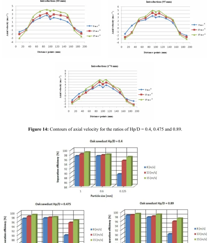
for Hp/D = 0.89 and at the inlet velocity of 8 m.s-1, 13 m.s-1 and 15 m.s-1. In the figures it is possible to see that the axial velocity near the cyclone wall achieves negative values and towards the cyclone centre these velocity values turn into positive ones. Higher values of the axial velocity were recorded in the centre of the cylindrical part than in the conical cyclone part. The cyclone hopper has negative values of axial velocity in the whole cross-section. The highest axial velocity is achieved near the wall of an exit tube.
Figure 14 shows the contours of axial velocity for the introduction at three inlet velocities.
The separation efficiency was investigated on a
The Effect of the Introduction of an Exit Tube on the Separation Efficiency in a Cyclone 635
(a) (b) (c) Figure 11: Contours of axial velocity for the ratio of Hp/D = 0.4 at the inlet velocity of: (a) 8 m.s-1;
(b) 13 m.s-1; (c) 15 m.s-1.
(a) (b) (c) Figure 12: Contours of axial velocity for the ratio of Hp/D = 0.475 at the inlet velocity of: (a) 8 m.s-1;
(b) 13 m.s-1; (c) 15 m.s-1.
(a) (b) (c) Figure 13: Contours of axial velocity for the ratio of Hp/D = 0.89 at the inlet velocity of: (a) 8 m.s-1;
Figure 14: Contours of axial velocity for the ratios of Hp/D = 0.4, 0.475 and 0.89.
The Effect of the Introduction of an Exit Tube on the Separation Efficiency in a Cyclone 637
In Figure 16 there is a simulation of the trajectory of oak particles with a size of 1 mm coloured according to the velocity size for Hp/D = 0.475 at the inlet velocity of 15 m.s-1; the time step was 0.2 s and the time stop was 10 s. From the figure it is possible to see that the particles achieve the highest
velocity at the inlet into the cyclone and the downwards along the conical cyclone part the velocity decreases. The fact that the velocity decreases is due to the abrasion of particles on the cyclone wall, the action of gravity and also the weight of newly arriving particles in the cyclone.
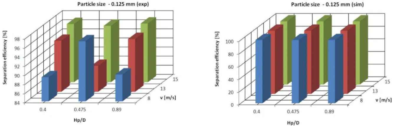
The following figure (Figure 17) shows a graphical dependence of the fractional separation by particle size for Hp/D = 0.475 for the flow velocities of 8, 13 and 15 m.s-1. The separation was investigated experimentally
for the fractions of 1 mm, 0.6 mm and 0.125 mm, parti-cle sizes that occur mainly in the wood-processing indus-try. A comparison of the experimental results with the outputs of CFD simulations can be seen in the Figure 18.
The Effect of the Introduction of an Exit Tube on the Separation Efficiency in a Cyclone 639
Figure 18: The efficiency of cyclone separation for diverse flow velocities, particle sizes and ratios of Hp/D.
CONCLUSIONS
1) From the experimental results and the CFD simulations it can be said that the introduction of an exit tube has a significant influence on the air flow and pressure losses in the cyclone and on the separation efficiency. By introducing an exit tube into a cylindrical cyclone at the ratio of Hp/D = 0.89, the vortex core was not created symmetrically along the whole central cyclone axis as it was at the ratios of Hp/D = 0.475 and 0.4.
2) Deep introduction of an exit tube into a cylindrical cyclone causes higher fluid flow velocity in the separation space of the cyclone, which is manifested in higher pressure cyclone losses.
3) In all three cases of the introduction of an exit tube, the vortex core is in the shape of a twisted cylinder and is not completely axially symmetrical, especially in the part of the conical cyclone towards the dust hopper. The axis of the forced vortex is not temporally coincident with the geometric cyclone axis, which is in the shape of a curve. With increasing inlet velocity, the length of turbulence in the cyclone is increased. CFD simulations were applied for particle sizes of 0.002 mm, 0.005 mm, 0.125 mm, 0.6 mm and 1 mm. The curve of fractional separation was also created from CFD simulations. It is obvious from the graph that the separation decreases upon reducing the particle size. Apart from the particle size impact, separation was also influenced by the geometrical ratios of the particular parts of the vortex separator.
4) With increasing inlet velocity to the cyclone the tangential velocity increases proportionally and this leads to an increase in the separation efficiency in the cyclone.
5) CFD simulations were used in the study of the physical phenomena occurring in the cyclone. The numerical results presented for axial and tangential velocity are in good agreement with the experimental ones.
process was environment humidity, which was reflected in the outputs from the experimental measurements as an influence of small particle agglomeration. It can be concluded that the optimal ratio of Hp/D under our conditions is 0.89.
NOMENCLATURE
CD drag coefficient dimensionless
d particle diameter m
Fi external body force N/m3
g acceleration of gravity m/s2
p′ dispersion pressure Pa
Rep particle Reynolds number dimensionless S ratio of particle density to
fluid density
dimensionless
t time s
u′ dispersion velocity m/s
u time average velocity in the axial direction
m/s
p i
u velocity of the particle m/s
v velocity m/s
x position m
Greek Letters
μ dynamic viscosity Pa.s
ν kinematic viscosity m2/s
ρ density kg/m3
Subscripts
i, j, k 1,2,3
p particle
ACKNOWLEDGMENTS
The contribution was created within the KEGA project no. 027TUZVO-4/2011 funded by the Ministry of Education, Science, Research and Sport of the Slovak Republic.
REFERENCES
Avci, A. and Karagoz, I., Effects of flow and geo-metrical parameters on the collection efficiency in cyclone separators. Journal of Aerosol Science, 34, No. 7, 937 (2003).
Barth, W., Design and layout of the cyclone separator on the basis of new investigations.
Brennstoff-Kraft (BWK), 8, 1 (1956).
Elsayed, Kh. and Lacor, C., The effect of vortex finder diameter on cyclone separator performance and flow field. ECCOMAS CFD Conf., J. C. F. Pereira and A. Sequeira (Eds.) Lisbon (2010). Griffiths, W. D. and Boyson, F., Computational Fluid
Dynamics (CFD) and empirical modeling of the performance of a number of cyclone samplers. Journal of Aerosol Science27, No. 2, 281 (1996). Hoffman, A. C., Jonge, R., Arends, H. and Hanrats,
C., Evidence of the natural vortex length and its effect on the separation efficiency of gas cyclones. Filtration & Separation, 32, No. 8, 799 (1995). Chen, J. and Shi, M., A universal model to calculate
cyclone pressure drop. Powder Technology, 171, No. 3, 184 (2007).
Karagoz, I. and Kaya, F., CFD investigation of the flow and heat transfer characteristics in a tangential inlet cyclone. International Communications in Heat and Mass Transfer, 34, No. 9-10, 1119 (2007). Kim, H. T., Lee, K. W. and Kuhlman, M. R.,
Exploratory design modifications for enhancing cyclone performance. Journal of Aerosol Science, 32, No. 10, 1135 (2001).
Lapple, C. E., Processes use many collector types. Chemical Engineering, 58, 144 (1951).
Launder, B. E., Reece, G. J. and Rodi, W., Progress in the development of a Reynolds-stress turbulent closure. Journal of Fluid Mechanics, 68, No. 3, 537 (1975).
Lidén, G. and Gudmundsson, A., Semi-empirical modeling to generalise the dependence of cyclone collection efficiency on operating conditions and cyclone. Journal of Aerosol Science, 28, No. 5, 853 (1996).
Lim, K. S., Kim, H. S. and Lee, K. W., Characteristics of the collection effciency for a cyclone with different vortex finder shapes. Journal of Aerosol Science, 35, No. 6, 743 (2004).
Martignoni, W. P., Bernardo, S. and Quintani, C. L., Evaluation of cyclone geometry and its influence on performance parameters by computational fluid dynamics (CFD). Brazilian Journal of Chemical Engineering, 24, No. 1, 83 (2007). Meier, H. F. and Mori, M., Gas-solid flow in
cyclones: The Eulerian approach. Computers & Chemical Engineering, 22, No. 1, 641 (1998). Muschelknautz, E. and Krambrock, W.,
Aerodyna-mische Beiwerte des Zyklonabscheiders aufgrund neuer und veberssertter Messungen. Chemie-Ingenieur-Technik, 42, No. 5, 247 (1970). (In German).
The Effect of the Introduction of an Exit Tube on the Separation Efficiency in a Cyclone 641
flow cyclone dust collector. Journal of Thermal Science,8, No. 3, 143 (1999).
Polansky, J. and Stech, J., Calibration of a five-port probe – in Czech. ZCU Plzen (2011).
Qian, F. and Wu, Y., Effects of the inlet section angle on the separation performance of a cyclone. Chemical Engineering Research and Design, 87, No. 12, 1567 (2009).
Raoufi, A., Shams, M., Farzaneh, M., and Ebrahimi, R., Numerical simulation and optimization of fluid flow in cyclone vortex finder. Chemical Engineering and Processing, 47, No. 1, 128 (2008).
Smith, J. L., An experimental study of the vortex in the cyclone separator. Journal of Basic Engineering, 84, No. 4, 602 (1962).
Wang, B., Xu, D. L., Chu, K. W. and Yu, A. B., Numerical study of gas-solid flow in a cyclone separator. Applied Mathematical Modelling, 30, No. 11, 1326 (2006).
Xiang, R., Park, S. H. and Lee, K. W., Effects of cone dimension on cyclone performance. Journal of Aerosol Science, 32, No. 4, 549 (2001). Zhu, I. and Lee, K. W., Experimental study on small