Catarina Alexandra
Louro Fernandes
COMPORTAMENTO CÍCLICO DE ELEMENTOS DE
BETÃO ARMADO COM ARMADURA LISA
CYCLIC BEHAVIOUR OF RC ELEMENTS WITH
PLAIN REINFORCING BARS
Catarina Alexandra
Louro Fernandes
COMPORTAMENTO CÍCLICO DE ELEMENTOS DE
BETÃO ARMADO COM ARMADURA LISA
CYCLIC BEHAVIOUR OF RC ELEMENTS WITH PLAIN
REINFORCING BARS
Dissertação apresentada à Universidade de Aveiro para cumprimento dos requisitos necessários à obtenção do grau de Doutor em Engenharia Civil, realizada sob a orientação científica do Prof. Doutor Humberto Salazar Amorim Varum, Professor Associado com Agregação do Departamento de Engenharia Civil da Universidade de Aveiro, e coorientação do Prof. Doutor Aníbal
Guimarães da Costa, Professor Catedrático do Departamento de Engenharia Civil da Universidade de Aveiro.
Apoio financeiro da FCT e do FSE no âmbito do III Quadro Comunitário de Apoio.
the jury
president Prof. Doutor António Carlos Matias Correia
professor catedrático da Universidade de Aveiro
Prof. Doutor Aníbal Guimarães da Costa professor catedrático da Universidade de Aveiro
Prof. Doutor Daniel Vitorino de Castro Oliveira
professor associado da Escola de Engenharia da Universidade do Minho
Prof. Doutor Humberto Salazar Amorim Varum professor associado com agregação da Universidade de Aveiro
Prof. Doutor Nelson Saraiva Vila Pouca
professor auxiliar da Faculdade de Engenharia da Universidade do Porto
Prof. Doutor Pedro da Silva Delgado
professor adjunto da Escola Superior de Tecnologias e Gestão do Instituto Politécnico de Viana do Castelo
acknowledgements To Professor Humberto Varum, supervisor of this thesis, for his excellent guidance and advice, encouragement and dedication.
To Professor Aníbal Costa, co-supervisor of this thesis, for his invaluable guidance and advice, namely in the development of the experimental programme.
To Eng. Hugo Rodrigues and Eng. José Melo, for their friendship, and their assistance in the experimental programme and numerical modelling of the tested specimens.
To Eng. António Figueiredo and Eng. Henrique Pereira, for their assistance in the experimental programme.
To Professor Romeu Vicente, for his assistance in the experimental testing of the RC beam.
To Eng. Randolph Borg, for his assistance in the numerical modelling of the beam-column joint specimens.
To Professor António Arêde, Eng. Alexandre Costa, Mr. Valdemar Luís and Mr. André Martins, from the LESE laboratory of the Faculty of Engineering of University of Porto, for their invaluable assistance in the experimental testing of the RC beam.
To Civilria Construções S.A, Somague, Grupo Meneses, Silva Tavares & Bastos Almeida, Paviútil, and Arlindo Correia & Filhos S.A, for the construction and transportation of the test specimens, and construction of the structural reaction systems used in the experimental programme.
To the Santa Joana Museum, in Aveiro, for giving access to the building from where the RC beam was collected.
To my fellow PhD students in room 28.02.05, for their friendship, patience and encouragement.
To Fundação para a Ciência e a Tecnologia, for the financial support provided in the form of the PhD grant with reference SFRH/BD/27406/2006.
To my parents and grandparents, for their unconditional support, patience and encouragement.
palavras-chave edifícios existentes de betão armado, armadura lisa, escorregamento, ensaios cíclicos, modelação numérica.
resumo O comportamento cíclico das estruturas de betão armado é fortemente condicionado pelo mecanismo de aderência entre o betão e o aço. O escorregamento relativo entre os dois materiais, resultante da degradação progressiva da aderência em elementos solicitados por ações cíclicas, é uma causa frequente de danos graves e até do colapso de estruturas devido à ocorrência de sismos. Entre as estruturas existentes de betão armado que foram dimensionadas e construídas antes da entrada em vigor dos
regulamentos sísmicos atuais, muitas foram construídas com armadura lisa, e portanto, possuem fracas propriedades de aderência. A informação disponível na literatura sobre o comportamento cíclico de elementos estruturais de betão armado com armadura lisa é reduzida e a influência das propriedades da aderência associadas a este tipo de armadura no comportamento cíclico das estruturas existentes não se encontra ainda devidamente estudada.
O objectivo principal desta tese foi estudar a influência do escorregamento na resposta cíclica de elementos estruturais de betão armado com armadura lisa. Foram realizados ensaios cíclicos em elementos do tipo nó viga-pilar,
construídos à escala real, representativos de ligações interiores em edifícios existentes sem pormenorização específica para resistir às ações sísmicas. Para comparação, foi realizado o ensaio de um nó construído com armadura nervurada. Foi ainda realizado o ensaio cíclico de uma viga de betão armado recolhida de uma estrutura antiga.
Foram elaborados modelos numéricos não-lineares para simular a resposta dos elementos ensaiados, concentrando especial atenção no mecanismo do escorregamento.
Os resultados obtidos no âmbito desta tese contribuem para o avanço do conhecimento sobre o comportamento cíclico de elementos estruturais de betão armado com armadura lisa. As análises numéricas realizadas comprovam a necessidade de incluir os efeitos do escorregamento na
modelação numérica deste tipo de estruturas de forma a representar com rigor a sua resposta às ações cíclicas.
keywords existing RC building structures, plain reinforcing bars, bond-slip, cyclic testing, numerical modelling.
abstract The hysteretic behaviour of reinforced concrete structures is highly dependent on the interaction between concrete and steel. The relative slippage between the steel reinforcing bars and the surrounding concrete, resulting from bond degradation under cyclic loading, is a common cause of severe damage and even collapse of reinforced concrete building structures due to earthquakes. Among the significant number of existing reinforced concrete buildings that were designed and built prior to the enforcement of the modern seismic-oriented design philosophies, many were built with plain reinforcing bars, thus with poor bond properties.
The available data about the cyclic behaviour of reinforced concrete structural elements with plain reinforcing bars is scarce. As a consequence, the influence of the bond properties on the hysteretic behaviour of existing reinforced
concrete structures containing this type of steel reinforcement is not yet comprehensively understood.
The main objective of this thesis was to investigate the influence of the bond-slip mechanism on the cyclic behaviour of reinforced concrete structural elements with plain bars. Cyclic tests were carried out on full-scale joint specimens representative of interior beam-column connections in existing reinforced concrete buildings without specific detailing for seismic demands. An additional joint specimen, with deformed bars, was also tested for comparison. A cyclic test was also performed on a two-span beam with plain bars that was collected from an ancient structure.
Nonlinear numerical models were built to simulate the response of the tested elements, giving particular attention to the bond-slip mechanism.
The tests results obtained in the framework of this thesis contribute to the advance of knowledge on the cyclic behaviour of reinforced concrete elements with plain reinforcing bars. The numerical analyses developed confirm the need of taking into account the effects of the bond-slip mechanism in the numerical modelling of this type of structures, in order to represent more accurately their cyclic response.
i CHAPTER 1 – INTRODUCTION, MAIN OBJECTIVES AND PLAN OF THE
THESIS
1.1 - INTRODUCTION ... 1
1.2 - MAIN OBJECTIVES OF THE THESIS ... 3
1.3 - PLAN OF THE THESIS ... 4
CHAPTER 2 – SEISMIC VULNERABILITY OF EXISTING RC BUILDING STRUCTURES WITH PLAIN REINFORCING BARS: STATE OF THE ART 2.1 - INTRODUCTION ... 7
2.2 - TYPICAL STRUCTURAL DEFICIENCIES AND COMMON CAUSES OF DAMAGE AND COLLAPSE DUE TO EARTHQUAKES ... 9
2.2.1 - Introduction ... 9
2.2.2 - The bond-slip mechanism ... 11
2.2.3 - Beam-column joints ... 17
2.3 - CONCRETE-STEEL BOND BEHAVIOUR OF PLAIN REINFORCING BARS ... 21
2.4 - PAST EXPERIMENTAL STUDIES ON THE CYCLIC BEHAVIOUR OF RC STRUCTURAL ELEMENTS WITH PLAIN REINFORCING BARS ... 27
2.4.1 - Beams ... 27
2.4.2 - Columns ... 28
2.4.3 - Beam-column joints ... 31
ii
CHAPTER 3 – CYCLIC TESTING OF INTERIOR RC BEAM-COLUMN JOINTS
3.1 - INTRODUCTION ... 39
3.2 - TEST SPECIMENS ... 39
3.2.1 - Geometrical characteristics and reinforcement detailing ... 39
3.2.2 - Materials ... 43
3.2.3 - Strength capacity prediction for the beam and column sections ... 44
3.2.4 - Comparison with modern code requirements for earthquake resisting structures ... 45
3.3 - TEST SETUP AND TESTING PROGRAMME ... 50
3.3.1 - Test setup ... 50
3.3.2 - Instrumentation ... 56
3.3.3 - Testing programme ... 57
3.4 - ANALYSIS OF TESTS RESULTS ... 59
3.4.1 - Lateral load versus drift diagrams ... 59
3.4.2 - Moment versus curvature diagrams and curvature demands ... 63
3.4.3 - Damage observed ... 67
3.4.4 - Shear forces and stresses in the joint ... 70
3.4.5 - Drift components ... 75
3.4.6 - Ultimate rotation capacity ... 79
3.4.7 - Energy dissipation ... 83
3.4.8 - Equivalent damping and ductility demands ... 86
3.4.9 - Damage index... 89
3.5 - INFLUENCE OF DISPLACEMENT HISTORY, AXIAL LOAD, BOND, AND STEEL REINFORCEMENT... 95
3.5.1 - Displacement history ... 95
3.5.2 - Column axial load ... 96
3.5.3 - Bond properties ... 99
3.5.4 - Amount of steel reinforcement ... 102
3.6 - SUMMARY ... 106
CHAPTER 4 – NUMERICAL MODELLING OF THE BEAM-COLUMN JOINTS 4.1 - INTRODUCTION ... 109
4.2 - NUMERICAL MODEL WITHOUT BOND-SLIP EFFECTS... 110
4.2.1 - Modelling strategy ... 110
4.2.2 - Material models ... 111
iii
4.2.4 - Comparison between the numerical and experimental results of the joint specimen
with deformed bars ... 114
4.2.5 - Comparison between the numerical and experimental results of the joint specimen with plain reinforcing bars ... 117
4.3 - NUMERICAL MODEL WITH BOND-SLIP EFFECTS ... 121
4.3.1 - Modelling strategy ... 121
4.3.2 - Material models ... 122
4.3.3 - Calibration of the rotational springs ... 123
4.3.4 - Loading pattern ... 128
4.3.5 - Comparison between the numerical and experimental results ... 128
4.4 - SUMMARY ... 132
CHAPTER 5 – CYCLIC TESTING OF A RC BEAM COLLECTED FROM AN EXISTING BUILDING STRUCTURE 5.1 - INTRODUCTION ... 133
5.2 - BEAM SPECIMEN ... 133
5.2.1 - Geometrical characteristics and reinforcement detailing ... 133
5.2.2 - Materials ... 135
5.2.3 - Comparison with modern codes requirements for earthquake resisting structures ... 136
5.3 - TEST SETUP, LOADING PATTERN AND INSTRUMENTATION ... 137
5.4 - TEST RESULTS ... 140
5.4.1 - Force-deflection diagrams ... 140
5.4.2 - Beam deflection and deformed shape, and rotation at supports ... 140
5.4.3 - Damage observed ... 142
5.4.4 - Energy dissipation ... 143
5.5 - SUMMARY ... 144
CHAPTER 6 – NUMERICAL MODELLING OF THE BEAM 6.1 - INTRODUCTION ... 145
6.2 - NUMERICAL MODEL OF THE BEAM ... 145
6.2.1 - Modelling strategy ... 145
6.2.2 - Material models ... 148
6.2.3 - Loading pattern ... 153
iv
6.3.1 - Force-displacement diagrams ... 154
6.3.2 - Damage evolution ... 155
6.3.3 - Energy dissipation ... 157
6.4 - ANALYSIS OF THE RESPONSE AT LOCAL LEVEL ... 158
6.4.1 - Evolution of bending moments ... 158
6.4.2 - Moment-curvature diagrams ... 160
6.4.3 - Evolution of the neutral axis position ... 160
6.4.4 - Stress-strain diagrams ... 161
6.5 - BOND-SLIP INFLUENCE ... 163
6.6 - SUMMARY ... 164
CHAPTER 7 – CONCLUSIONS AND FUTURE RESEARCH 7.1 - CONCLUSIONS ... 167
7.2 - FUTURE RESEARCH ... 168
REFERENCES ... 171
v
TABLE OF FIGURES
CHAPTER 2 – SEISMIC VULNERABILITY OF EXISTING RC BUILDING STRUCTURES WITH PLAIN REINFORCING BARS:
STATE OF THE ART
Figure 2.1 - Column shear failure: a) 1999 Izmit, Turkey earthquake (photo by Halil Sezen, courtesy of the National Information Service for Earthquake Engineering, EERC, University of California, Berkeley [14]); b) 1985 Mexico City earthquake [2] ... 10 Figure 2.2 - Inadequate lap-splices and lack of stirrups (1999 Izmit, Turkey earthquake) [2] ... 10 Figure 2.3 - Building collapse due to soft-storey mechanism in the: a) 2009 L’Aquila, Italy
earthquake [15]; b) 1999 Izmit, Turkey earthquake (photo by Halil Sezen, courtesy of the National Information Service for Earthquake Engineering, EERC, University of California, Berkeley [14]) ... 10 Figure 2.4 - Failure of beam-column joints lacking proper design: a) 2011 Lorca, Spain
earthquake; b) 1999 Izmit, Turkey earthquake) [2] ... 11 Figure 2.5 - Comparative results on effect of type of reinforcement on drift capacity [22] ... 13 Figure 2.6 - Experimental and numerical responses of the beam-column joint analysed by
Limkatanyu and Spacone [28]: a) model with slip; b) model without
bond-slip ... 14 Figure 2.7 - Correction of the steel reinforcement constitutive law for taking into account
bond-slip, as proposed by Varum [2] ... 15 Figure 2.8 - Storey shear-drift response of a RC frame with plain reinforcing bars
(pseudo-dynamic test) [36]: a) numerical results considering and not considering bond-slip; b) comparison between experimental results and numerical results considering
bond-slip ... 16 Figure 2.9 - Interior beam-column joint subjected to seismic loading [46] ... 17 Figure 2.10 - Joint models proposed by: a) Youssef and Ghobarah [60]; b) Shin and LaFave
[63]; c) Lowes and Altoontash [41]; d) Altoontash [62] ... 20 Figure 2.11 - Joint model proposed by Calvi et al. [50] ... 21 Figure 2.12 - Bond stress-slip relationship given by CEB-FIP Model Code 90 for deformed
bars [2, 68] ... 24 Figure 2.13 - Bond stress-slip relationship given by CEB-FIP Model Code 90 for plain bars
vi
Figure 2.14 - Bond stress-slip relationship according to Eligehausen et al. [79] and modified by Cozenza et al. [82] (a), and comparison with test results from Verderame et al. [70] (b) ... 25 Figure 2.15 - Bond-slip models for cyclic loading (deformed bars) proposed by: a) Tassios
[84] (monotonic envelope and cyclic rules); b) Morita and Kaku [85];
c) Viwathanatepa et al. [86], d) Hawkins et al. [87]; e) Eligehausen et al. [79] ... 26 Figure 2.16 - Cyclic bond-slip model for plain reinforcing bars proposed by Verderame et al.
[70]: a) hysteretic bond-slip relationship; b) summary of the model parameters ... 27 Figure 2.17 - Results of the experimental tests on RC beams carried out by Marefat et al. [88]:
a) crack pattern at ultimate state; b) deformation components in specimens PC-C2 (plain bars) and DC-C2 (deformed bars) ... 28 Figure 2.18 - Experimental campaign on RC columns carried out by Verderame et al. [24, 25]:
a) column specimens and materials properties; b) test setup and displacement
histories; c) column base rotation versus drift relationships ... 29 Figure 2.19 - Test specimens and test setup of the experimental tests on beam-column joints
with plain and deformed reinforcing bars reported in [97]: a) interior beam-column joints; b) exterior beam-column joints ... 32 Figure 2.20 - Experimental campaign on RC joints carried out by Pampanin et al. [8]: a) joint
specimens and materials properties; b) test setup and displacement history; c) test results for the exterior joint specimens (force-drift diagrams, damage and
development of the “concrete wedge” mechanism); d) tests result for the interior joint specimens (force-drift diagrams and comparison between anchorage solutions) ... 33 Figure 2.21 - Differences recorded between the deep beam joint specimens with plain and
deformed reinforcing bars (final damage state and hysteretic envelopes) tested by Hertanto [12] ... 34 Figure 2.22 - Cyclic testing of exterior beam-column joints carried out by Bedirhanoglu et al.
[100]: a) joint specimens and material properties; b) test setup and displacement
histories; c) final damage state (examples) ... 35 Figure 2.23 - Comparison between beam-column joint specimens with plain and deformed
reinforcing bars [101]: a) final damage state in beam-column joint specimens;
b) storey shear versus storey displacement for the interior joints ... 36 Figure 2.24 - Experimental investigation on retrofitting techniques for exterior beam-column
joints carried out by: a) Akguzel and Pampanin [106]; b) Genesio et al. [104] ... 37 Figure 2.25 - Full-scale RC frame models pseudo-dynamically tested at the ELSA laboratory
in the framework of the research programme: a) ICONS [2]; b) SPEAR [110] ... 38
CHAPTER 3 – CYCLIC TESTING OF INTERIOR RC BEAM-COLUMN JOINTS
Figure 3.1 - Idealization of the beam-column joint elements under investigation ... 40 Figure 3.2 - Dimensions and reinforcement detailing of specimens JPA-1, JPA-2, JPA-3,
and JD... 42 Figure 3.3 - Dimensions and reinforcement detailing of specimen JPB ... 42 Figure 3.4 - Dimensions and reinforcement detailing of specimen JPC ... 43
vii
Figure 3.5 - Methods of anchorage other than by straight bars according to EC2 [3] ... 49
Figure 3.6 - Schematics of the test setup ... 51
Figure 3.7 - General view of the test setup... 52
Figure 3.8 - Location and details of the high-load carrying capacity devices used to support the self-weight of the joint specimens ... 52
Figure 3.9 - Reaction frames and sliding devices designed to simulate the support conditions of the beams ... 53
Figure 3.10 - Reaction frames and pinned connection designed to simulate the support conditions of the columns ... 54
Figure 3.11 - Reaction frame and hydraulic servo-actuator used to impose the lateral displacements ... 55
Figure 3.12 - Method used to impose the column axial load ... 56
Figure 3.13 - LVDTs setup ... 57
Figure 3.14 - Lateral displacement history: a) type 1; b) type 2 ... 58
Figure 3.15 - Lateral load versus drift diagrams of the beam-column joint specimens ... 60
Figure 3.16 - Peak envelopes of the lateral load-drift diagrams ... 61
Figure 3.17 - Strength degradation: a) absolute values; b) values normalized to the maximum lateral load ... 62
Figure 3.18 - Secant stiffness degradation: a) absolute values; b) values normalized to the secant stiffness at 0.3% drift ... 62
Figure 3.19 - Moment-curvature diagrams of slice 1 in the beams ... 64
Figure 3.20 - Moment-curvature diagrams of slice 1 in the columns ... 65
Figure 3.21 - Maximum mean curvatures of slice 1 ... 67
Figure 3.22 - General damage distribution observed in the specimens with plain reinforcing bars (a) and damage distribution in the specimen with deformed bars (b) ... 68
Figure 3.23 - Damage state at maximum drift... 69
Figure 3.24 - Crack pattern corresponding to the final damage state ... 70
Figure 3.25 - Principal tensile stress versus drift diagrams ... 74
Figure 3.26 - Analytical formulation adopted for determining the deformation equations ... 76
Figure 3.27 - Relative contribution of beams and columns to the total drift ... 78
Figure 3.28 - Relative contribution of linear elastic deformation and nonlinear deformation to the total drift ... 79
Figure 3.29 - Lateral load versus column chord rotation diagrams ... 83
Figure 3.30 - Evolution of dissipated energy ... 84
Figure 3.31 - Relative contribution of beams and columns to the total dissipated energy ... 85
Figure 3.32 - Equivalent damping versus displacement ductility: a) experimental results; b) comparison with the results from existing equivalent damping equations ... 88
Figure 3.33 - Time evolution of the PA damage index for specimen JPA-1 ... 92
Figure 3.34 - Time evolution of the PA damage index for specimen JPA-2 ... 92
viii
Figure 3.36 - Time evolution of the PA damage index for specimen JPB ... 93
Figure 3.37 - Time evolution of the PA damage index for specimen JPC ... 94
Figure 3.38 - Time evolution of the PA damage index for specimen JD ... 94
Figure 3.39 - Lateral load-drift diagrams of specimens JPA-1 and JPA-2 ... 95
Figure 3.40 - Moment-curvature diagrams of specimens JPA-1 and JPA-2 ... 96
Figure 3.41 - Lateral load-drift diagrams of specimens JPA-1 and JPA-3 ... 97
Figure 3.42 - Moment-curvature diagrams of specimens JPA-1 and JPA-3 ... 98
Figure 3.43 - Tensile stress-drift diagrams of specimens JPA-1 and JPA-3 ... 98
Figure 3.44 - Lateral load-drift diagrams of specimens JPA-1 and JD ... 99
Figure 3.45 - Moment-curvature diagrams of specimens JPA-1 and JD ... 100
Figure 3.46 - Maximum curvature for JPA-1 and JD ... 101
Figure 3.47 - Tensile stress-drift diagrams of specimens JPA-1 and JD... 102
Figure 3.48 - Lateral load-drift diagrams of specimens JPA-3 and JPB ... 103
Figure 3.49 - Lateral load-drift diagrams of specimens JPB and JPC... 103
Figure 3.50 - Moment-curvature diagrams of specimens JPA-3 and JPB ... 104
Figure 3.51 - Moment-curvature diagrams of specimens JPB and JPC ... 105
Figure 3.52 - Tensile stress-drift diagrams of specimens: a) JPA-3 and JPB; b) JPB and JPC ... 105
CHAPTER 4 – NUMERICAL MODELLING OF THE BEAM-COLUMN JOINTS Figure 4.1 - Model adopted to simulate the response of the beam-column joint specimens... 111
Figure 4.2 - Stress-strain model for monotonic loading of confined and unconfined concrete proposed by Mander et al. [2] ... 112
Figure 4.3 - Menegotto-Pinto steel model (a) and definition of curvature parameter R [6] (b) ... 113
Figure 4.4 - Loading conditions in the numerical models ... 114
Figure 4.5 - Lateral load-drift diagrams of specimen JD (experimental and numerical) ... 115
Figure 4.6 - Evolution of dissipated energy for specimen JD (experimental and numerical) ... 115
Figure 4.7 - Moment-curvature diagrams of the beams for specimen JD (experimental and numerical) ... 117
Figure 4.8 - Moment-curvature diagrams of the columns for specimen JD (experimental and numerical) ... 117
Figure 4.9 - Lateral load-drift diagrams of specimen JPA-1 (experimental and numerical) ... 118
Figure 4.10 - Evolution of dissipated energy for specimen JPA-1 (experimental and numerical) . 119 Figure 4.11 - Moment-curvature diagrams of the beams for specimen JPA-1 (experimental and numerical) ... 120
Figure 4.12 - Moment-curvature diagrams of the columns for specimen JPA-1 (experimental and numerical) ... 120
ix
Figure 4.13 - Joint model by: a) Lowes and Altoontash (adapted from [7]); b) Yu (adapted
from [8]) ... 121
Figure 4.14 - Model with rotational springs ... 122
Figure 4.15 - Derivation procedures of the moment-rotation relationships of the bar slip rotational springs in the joint model proposed by Yu [8] ... 123
Figure 4.16 - Response curves assigned to the spring elements: a) in the beams (bilinear asymmetric curve); b) in the columns (simplified bilinear Takeda curve) ... 126
Figure 4.17 - Lateral load-drift diagrams of specimen JPA-1 (experimental and numerical with and without considering bond-slip) ... 128
Figure 4.18 - Evolutions of dissipated energy for specimen JPA-1 (experimental and numerical with and without considering bond-slip) ... 129
Figure 4.19 - Moment-curvature diagrams of slice 1 in the beams of specimen JPA-1 (experimental and numerical with and without considering bond-slip) ... 130
Figure 4.20 - Moment-curvature diagrams of slice 2 in the beams of specimen JPA-1 (experimental and numerical with and without considering bond-slip) ... 131
Figure 4.21- Moment-curvature diagrams of slice 1 in the columns of specimen JPA-1 (experimental and numerical with and without considering bond-slip) ... 131
Figure 4.22 - Moment-curvature diagrams of slice 2 in the columns of specimen JPA-1 (experimental and numerical with and without considering bond-slip) ... 131
CHAPTER 5 – CYCLIC TESTING OF A RC BEAM COLLECTED FROM AN EXISTING BUILDING STRUCTURE Figure 5.1 - Steel reinforcement detailing ... 134
Figure 5.2 - Support conditions adopted in the cyclic test and identification of spans and supports ... 137
Figure 5.3 - Test setup: a) schematics; b) general view ... 138
Figure 5.4 - Vertical loading history ... 139
Figure 5.5 - Vertical displacements and rotations monitored in the cyclic test... 139
Figure 5.6 - Force-deflection diagrams ... 140
Figure 5.7 - Evolution of the spans deflection ... 141
Figure 5.8 - Evolution of the beam’s deformed shape ... 141
Figure 5.9 - Force-rotation (absolute values) diagrams for the left and right supports ... 142
Figure 5.10 - Location and length of the plastic hinges ... 142
x
CHAPTER 6 – NUMERICAL MODELLING OF THE BEAM
Figure 6.1 - Numerical model adopted for the RC beam (adapted from [3]): elements’ location and dimensions, plastic hinge lengths, and cross-section of the beam ... 146 Figure 6.2 - Beam-column element BeamWithHinges linked to the Zero-length Section
element ... 148 Figure 6.3 - Concrete01 and Concrete02 material models (adapted from [4]) ... 149 Figure 6.4 - Confinement effect in the concrete model according to Guedes [6] ... 150 Figure 6.5 - Bar stress-slip model proposed by Zhao and Sritharan [5]: a) envelope curve;
b) hysteretic response ... 152 Figure 6.6 - Vertical mid-span displacements imposed in the numerical model ... 153 Figure 6.7 - Force-displacement diagrams (numerical and experimental): a) left mid-span
section; b) right mid-span section ... 154 Figure 6.8 - Numerical force-displacement diagrams of the left mid-span and right mid-span
sections ... 155 Figure 6.9 - Damage evolution at: a) left mid-span section; b) right mid-span section ... 156 Figure 6.10 - Evolution of the total dissipated energy (numerical and experimental) ... 157 Figure 6.11 - Evolution of bending moments... 159 Figure 6.12 - Bending moment diagrams (in kNm) ... 159 Figure 6.13 - Moment-curvature diagrams... 160 Figure 6.14 - Evolution of the neutral axis position ... 161 Figure 6.15 - Relative contributions of bond-slip and bending to the mid-span displacement of
the: a) left span; b) right span ... 163 Figure 6.16 - Force-displacement diagrams (experimental and numerical with and without
bond-slip): a) left mid-span section; b) right mid-span section ... 164 Figure 6.17 - Evolution of the total dissipated energy (experimental and numerical with and
xi
TABLE OF TABLES
CHAPTER 2 – SEISMIC VULNERABILITY OF EXISTING RC BUILDING STRUCTURES WITH PLAIN REINFORCING BARS:
STATE OF THE ART
Table 2.1 - Parameters (mean values) of the bond stress-slip relationship of deformed bars [68] ... 24 Table 2.2 - Parameters (mean values) of the bond stress-slip relationship of plain bars [2, 68] ... 24
CHAPTER 3 – CYCLIC TESTING OF INTERIOR RC BEAM-COLUMN JOINTS
Table 3.1 - Steel reinforcement details ... 41 Table 3.2 - Mechanical properties of the steel reinforcement (mean values)... 44 Table 3.3 - Flexural and shear capacities of the beams and columns computed according
to EC2... 45 Table 3.4 - EC2 and EC8-1 provisions about maximum distance between beam transverse
reinforcing bars (in mm) ... 46 Table 3.5 - EC8-1 provisions for minimum mechanical volumetric ratio of column transverse
reinforcement ... 47 Table 3.6 - EC2 and EC8-1 provisions about maximum distance between column transverse
reinforcing bars (in mm) ... 48 Table 3.7 - Lateral displacement histories... 58 Table 3.8 - Column axial load and type of lateral displacement history imposed on the joint
specimens ... 59 Table 3.9 - Maximum lateral load and maximum strength degradation ... 61 Table 3.10 - Ratio between the maximum moment and the moment capacity according to EC2... 63 Table 3.11 - Drift corresponding to the onset of cracking and maximum crack opening ... 68 Table 3.12 - Maximum values of horizontal shear force and maximum principal tensile stress
in the joint ... 73 Table 3.13 - Values adopted for the parameters involved in the computation of the ultimate
xii
Table 3.14 - Theoretical values of ultimate rotation capacity ... 81 Table 3.15 - Maximum chord rotation and ratio to theoretical values of ultimate rotation
capacity ... 83 Table 3.16 - Energy dissipation... 84 Table 3.17 - Equivalent damping and displacement ductility at the maximum drift ... 87 Table 3.18 - Values estimated for the strength degradation parameter (β) and ultimate
displacement (uu) ... 90
Table 3.19 - Calculated damage index versus observed damage [18] ... 91
CHAPTER 4 – NUMERICAL MODELLING OF THE BEAM-COLUMN JOINTS
Table 4.1 - Values adopted for the concrete model parameters ... 112 Table 4.2 - Values adopted for the steel model parameters ... 113 Table 4.3 - Average bond strengths as function of steel stress state [7] ... 124 Table 4.4 - Values adopted for the parameters of the rotational springs in the beams ... 127 Table 4.5 - Values adopted for the parameters of the rotational springs in the columns ... 127
CHAPTER 5 – CYCLIC TESTING OF A RC BEAM COLLECTED FROM AN EXISTING BUILDING STRUCTURE
Table 5.1 - Steel reinforcement detailing ... 134 Table 5.2 - Results of the compression tests and correction of the concrete strength according
to ASTM C42/C42M [4] ... 135 Table 5.3 - Strength correction factors for L/D values between 1.00 and 1.75 [4] ... 135
CHAPTER 6 – NUMERICAL MODELLING OF THE BEAM
Table 6.1 - Values adopted for the Concrete01 and Concrete02 models parameters ... 149 Table 6.2 - Values adopted for the Steel02 model parameters ... 151 Table 6.3 - Values adopted for the Bond_SP01 model parameters ... 153 Table 6.4 - Parameters involved in the computation of the ultimate rotation capacity of the
beam according to EC8-3 ... 157 Table 6.5 - Comparison between the beam flexural strength computed according to EC2 and
the numerical values of maximum moment ... 159 Table 6.6 - Stress and strain distributions in the cross-section of the beam (left mid-span
1
INTRODUCTION, MAIN OBJECTIVES AND PLAN OF THE THESIS
1.1 - INTRODUCTION
The hysteretic behaviour of reinforced concrete (RC) structures is strongly dependent on the interaction between the concrete and the steel reinforcement.
Cyclic load reversals, like those induced by earthquakes, lead to progressive bond degradation. The resulting relative slippage between the reinforcing bars and the surrounding concrete, which is commonly addressed as bond-slip, is one of the common causes of severe damage and even collapse of RC structures due to earthquakes.
A significant number of existing RC building structures located in seismic-prone countries all over the world was designed and built before the 1970s, prior to the enforcement of the modern seismic-oriented design philosophies, thus lacking adequate ductility and specific detailing for seismic demands. Many of these structures were built with plain reinforcing bars, to which are associated poor concrete-steel bond properties. Premature bond degradation and significant bar slippage are expected to occur in RC structural elements with plain bars subjected to moderate to severe cyclic loading, making this type of structures particularly sensitive to the bond-slip mechanism.
In critical regions, like base of columns and beam-column joints, the bond-slip mechanism can have a significant contribution to the elements’ lateral deformation hence to the overall response of the structures. Reduction in stiffness and in energy dissipation capacity are also commonly associated with the occurrence of bar slippage. The complex behaviour of beam-column joints, for example, is highly influenced by the concrete-steel bond
2
properties, and bond degradation can dramatically alter the force transfer mechanisms within the joint region, with consequent load redistribution and impact on the joint strength. However, bond-slip is typically neglected in the numerical analysis of RC structures. Also, the specifications of the modern design codes were developed under the assumption of perfect bond between concrete and steel. In this way, the seismic response of RC structures with plain reinforcing bars can be significantly different from the theoretical predictions.
Despite the increasing number of research work devoted to the analysis of the cyclic behaviour of RC structural elements representative of non-seismic resisting structures, there is still a recognised lack of information about the performance of substandard elements with plain reinforcing bars.
When compared to the amount of information provided in the literature for elements with deformed bars, namely in terms of experimental data, the information available for elements with plain bars is scarce. The same can be said about the concrete-steel bond behaviour. In fact, a comprehensive model for describing the cyclic bond stress-slip relationship has not yet been established for this type of steel reinforcement.
It should be noted that an extensive experimental database (covering a wide range of loading conditions, typical geometrical and structural detailing characteristics, and materials mechanical properties) is fundamental to calibrate and upgrade numerical models for the adequate simulation of the cyclic behaviour of this type of elements. The development of simple modelling strategies, which take into account the influence of the bond-slip mechanism on the elements’ response, is also highly dependent on the extension of the available experimental database. Various modelling strategies for simulating the bar slippage effects are proposed in the literature, but the majority is limited to the analysis of specific types of elements or, in some cases, quite complex to implement. As a consequence of the lack of experimental data and of general and reliable models for simulating the bond-slip mechanism, the influence of the bond properties of plain reinforcing bars on the hysteretic behaviour of existing RC structures built with this type of steel reinforcement is not yet completely understood.
3 1.2 - MAIN OBJECTIVES OF THE THESIS
The main objective of this thesis was to study the influence of the bond-slip mechanism on the cyclic behaviour of RC structural elements with plain reinforcing bars. More specifically, this research aimed to:
i) Collect and analyse relevant information provided in the scientific literature about the cyclic behaviour of RC structural elements with plain reinforcing bars, identifying needs for future research and limitations;
ii) Contribute to the characterization of the cyclic behaviour of RC structural elements with plain reinforcing bars, by analysing the influence of various parameters, with focus placed on the bond properties, and establishing the comparison with the major findings from similar research work provided in the literature;
iii) Contribute to enlarge the available experimental database on the cyclic behaviour of RC structural elements with plain reinforcing bars, which can be used to calibrate and upgrade numerical models for the adequate simulation of the cyclic response of this type of elements.
In order to achieve these objectives, the work was developed in three main parts:
i) Literature review on the main sources of seismic vulnerability of existing RC building structures designed and built before the enforcement of the modern seismic-oriented design philosophies, and on the available data about the cyclic behaviour of RC structural elements with plain reinforcing bars.
ii) Cyclic tests on full-scale RC structural elements with plain reinforcing bars and structural detailing similar to that typically adopted in RC building structures designed and built before the 1970s, namely a set of joint specimens representative of interior beam-column connections, and a two-span RC beam that was collected from an existing structure.
iii) Numerical modelling of the experimental response of the tested specimens using nonlinear fibre-based models and paying particular attention to the bond-slip mechanism.
4
1.3 - PLAN OF THE THESIS
This thesis is organized in seven chapters. Following the introduction, Chapter 2 presents a review on the main sources of seismic vulnerability in existing RC building structures designed and built before the enforcement of the modern seismic-oriented design philosophies. The structural deficiencies typically found in these structures, and the main causes of damage and collapse due to earthquakes are summarized. Focus is placed on the effects of the bond-slip mechanism and on the vulnerability of beam-column joints. Focusing on RC structural elements with plain reinforcing bars, a discussion about the bond performance of plain bars, and a review on recent experimental campaigns carried out for assessing the cyclic behaviour of this type of elements are presented. The chapter highlights the key role of the concrete-steel bond properties in the performance of RC elements with plain reinforcing bars and also the lack of information and need for more investigation work on the subject.
Chapter 3 addresses the cyclic testing of the RC beam-column joints. The specimens’ properties, and the test setup and testing programme are described. The main experimental results are presented and analysed. The influence of various parameters on the joints performance is investigated, paying particular attention to the effects of the bond properties.
Chapter 4 is devoted to the numerical modelling of the beam-column joint specimens. The adopted modelling strategies and assumptions are presented, and comparisons are established between the numerical and experimental results. Particular focus is placed on the influence of the bond-slip mechanism on the joint specimens’ response.
Chapter 5 reports the cyclic testing of the RC beam. The beam properties, and the test setup and procedure are described, and the main experimental results are presented.
Chapter 6 addresses the numerical modelling of the RC beam. The adopted modelling strategy and assumptions are presented. Comparison is established between the numerical and experimental results. Particular attention is paid to the influence of the bond-slip mechanism on the beam response.
5 Finally, Chapter 7 summarizes the main conclusions resulting from the research work, identifying the main contributions, as well as the limitations, and gives suggestions for further developments and possible research directions.
The references of the papers published in journals and articles presented in conferences, in the framework of the PhD thesis, are listed in the Appendix.
7
SEISMIC VULNERABILITY OF EXISTING RC BUILDING
STRUCTURES WITH PLAIN REINFORCING BARS:
STATE OF THE ART
2.1 - INTRODUCTION
The incorporation of seismic design procedures in building design was first adopted in a general sense in the 1920s and 1930s. Lateral forces corresponding to a fraction of the building weight and elastic design to permissible stress levels were in force, what later was verified to be not an adequate design strategy [1].
As stated by Varum [2], until the 1950s in the US and the 1960s in Europe, there were essentially no formal seismic design provisions in design codes. It was only in the mid-1970s that provisions for design and detailing of members and structures came out in the US standards. Yet, it was not before the mid-1980s that these provisions were included in the European national codes. Until then, only seismic equivalent lateral loading was considered in seismic design. For example, in Portugal, the first provisions for seismic design appeared in 1958 (RSCCS [3]), but rules resembling those of modern codes were only introduced in 1983 (RSA [4]). In Greece, which is one of the most earthquake-prone countries in Europe, the first modern earthquake resistant design code was only introduced in 1992, becoming mandatory in 1995 [2]. In Italy, before the current design codes came into force, only in 1975 did the dynamic properties of the structures became considered in the Italian regulations [5]. Nowadays, together with the remaining Eurocodes (like Eurocode 2 (EC2, [6]) for RC structural design), Eurocode 8 [7] is the reference standard for seismic design in many European countries.
8
In general, the 1970s were a turning point in the design and construction practice all around the world. In particular, capacity design principles were introduced, highlighting the key role of ductility, instead of lateral strength, in preventing structural collapse and excessive damage during seismic events. Selection of a suitable structural configuration for inelastic response, selection of a suitable and appropriately detailed location (plastic hinges) for inelastic deformations to be concentrated, and insurance (through suitable strength differentials) that inelastic deformation does not occur in undesirable locations or by undesirable structural modes, are the basis for the capacity design philosophy [1]. For instance, a beam sway mechanism instead of a column sway mechanism (soft-storey) is more desirable, and failures due to shear (implying large degradation of strength and stiffness) and loss of reinforcement anchorage should be prevented.
A significant number of existing RC structures, located in seismic-prone countries all over the world, was built before the 1970s [2] hence prior to the enforcement of the modern seismic-oriented design philosophies. As a consequence of the absence of capacity design principles in design and poor reinforcement detailing, a significant lack of ductility, at both local and global levels, is expected for these structures, resulting in inadequate structural performance even under moderate seismic excitations [8]. This type of structures is referred to herein as old-type structures. Damage and collapse of building structures observed in recent severe earthquakes, confirm the important source of risk that old-type RC buildings represent to society, in both human and economic terms. In Portugal, for example, the survey [9] on the Portuguese residential park that was conducted in 1991 revealed the predominance of RC buildings, indicating that, by that year, 56% of the total residential buildings had been constructed between 1961 and 1991 [2].
Deformed reinforcing bars are currently used in the RC construction. However, the use of plain bars as longitudinal (and transverse) steel reinforcement in RC building structures was quite common until the mid-1960 (in the US) up to the mid-1980s (in some European countries) [10]. For example, in Italy and in the whole Mediterranean area, the use of plain reinforcing bars was widely spread up to 1970 [11]. Thus, a significant number of existing old-type RC buildings around the world has plain bars as steel reinforcement.
In the next sections, the main structural deficiencies commonly found in old-type RC building structures are briefly described, as well as the most common causes of damage
9 and collapse of buildings due to earthquakes. Particular attention is given to the influence of the concrete-steel bond properties and to the cyclic behaviour of beam-column joints. Focusing on RC elements with plain reinforcing bars, a discussion on the bond mechanism, and a review of the experimental work reported in the available literature aimed at the investigation of the cyclic behaviour of this type of elements, are presented.
2.2 - TYPICAL STRUCTURAL DEFICIENCIES AND COMMON CAUSES OF DAMAGE AND COLLAPSE DUE TO EARTHQUAKES
2.2.1 - Introduction
Typical structural deficiencies found in old-type RC building structures, that constitute recognised sources of seismic vulnerability, are [2, 8, 12]: i) lack of appropriate confinement through transverse reinforcement in the plastic hinge regions; ii) lack or absence of joint transverse reinforcement; iii) moment capacity of the columns lower than the moment capacity of the beams (weak column-strong beam mechanism); iv) inadequate
anchorage solutions; v) lapped splices located in potential plastic hinge regions;vi) lower
quality of materials when compared to current practice, in particular the use of plain reinforcing bars as longitudinal reinforcement and of low-strength concrete; and, vii) presence of masonry infill walls with complex interaction with the bare frame. Causes of damage and collapse of old-type RC building structures due to earthquakes are also frequently associated with vertical and horizontal irregularities.
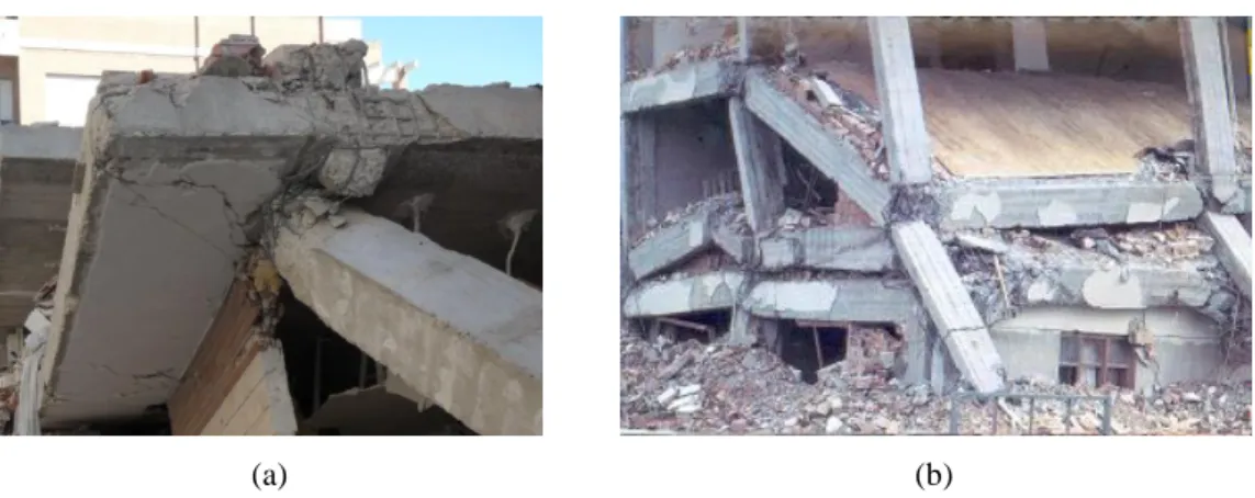
Shear failure can occur in beams due to both insufficient steel reinforcement and the increase in loads during the earthquake [13]. Shear forces in columns resulting from typical gravity and wind load designs can be significantly lower than those developed during seismic loading. Shear failure in columns is frequently observed (Figure 2.1). Poor confinement (associated with inadequate spacing of stirrups or presence of ties) can result in flexural crisis at the base of columns located at low levels (Figure 2.2), with instability of the compressive reinforcement, slippage of the tensile reinforcing bars and crushing of the unconfined concrete [13]. Soft-storey mechanisms are one of the most common causes of building collapse due to earthquakes (Figure 2.3).
10
(a) (b)
Figure 2.1 - Column shear failure: a) 1999 Izmit, Turkey earthquake (photo by Halil Sezen, courtesy of the National Information Service for
Earthquake Engineering, EERC, University of California, Berkeley [14]); b) 1985 Mexico City earthquake [2].
Figure 2.2 - Inadequate lap-splices and lack of stirrups
(1999 Izmit, Turkey earthquake) [2].
(a) (b)
Figure 2.3 - Building collapse due to soft-storey mechanism in the: a) 2009 L’Aquila, Italy earthquake [15]; b) 1999 Izmit, Turkey earthquake (photo by Halil Sezen, courtesy of the National Information Service for
Earthquake Engineering, EERC, University of California, Berkeley [14]).
The risk of collapse of RC building structures due to seismic events is often associated with the brittle failure of beam-column joints (Figure 2.4). The type of joint damage or failure mechanism is mainly dependent on the joint typology (exterior or interior joint), adopted structural details (such as the amount of joint transverse reinforcement and anchorage solution), and concrete-steel bond properties (see Section 2.2.3). Beam-column joints in old-type RC building structures typically lack appropriate joint transverse reinforcement (sometimes only one stirrup was used, but it was common the absence of transverse reinforcement), as well as appropriate anchorage and bond properties.
11
(a) (b)
Figure 2.4 - Failure of beam-column joints lacking proper design: a) 2011 Lorca, Spain earthquake; b) 1999 Izmit, Turkey earthquake) [2].
2.2.2 - The bond-slip mechanism
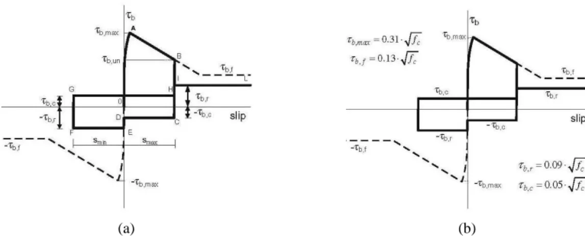
Concrete-steel bond is the mechanism that allows the force transfer between the steel reinforcing bars and the surrounding concrete in RC structures. It is a combination of [16]: i) adhesion, which is related to the shear strength of the steel-concrete interface and results primarily from chemical bonding; ii) bearing forces perpendicular to the lug faces, which arise as the bar is loaded and tries to slide; and, iii) friction, which is produced by bearing force on the concrete-steel surface and by shearing off the concrete between the lugs on the cylindrical concrete surface at the tip of the lugs. Detailed explanation about the different stages that characterise the interaction between concrete and steel can be found in [17]. Bond action is not only necessary to ensure an adequate level of safety by allowing the concrete and steel to work together, but also to control the structural behaviour by providing an adequate level of ductility. While safety requires bond to have good mechanical properties at the local level, ductility requires bond to withstand large steel strains along the embedded reinforcement in order to let the strains spread between two continuous bending cracks, and to favour the formation of densely-spaced secondary cracks in the concrete [17].
The hysteretic behaviour of RC structures is highly dependent on the concrete-steel interactional mechanisms. Cyclic load reversals (like those induced by earthquakes) lead to progressive bond degradation, resulting in significant relative slippage between the reinforcing bars and the surrounding concrete, which is commonly addressed as bond-slip. The sudden loss of bond, and consequent bar slippage, is acknowledged as one of the
12
sources of brittle failure in RC structural elements, and is reported to have been the cause of severe local damage and even collapse of many structures due to earthquakes [2]. In RC structural elements subjected to cyclic loading, the concrete-steel bond can deteriorate even before the stress state has attained the yield stress of the steel and the stress strength of the concrete [2, 18].
Bond failure can occur due to [16]: i) direct pullout of the reinforcing bar, if ample confinement is provided for the reinforcing bars (observed as fixed-end rotations at the elements ends, like in column bases and beam-column joints); or, ii) splitting of the concrete cover along the bar, if the concrete cover or confinement is insufficient to obtain a pullout failure. The failure modes under monotonic loading and cyclic loading are similar. However, particularly under reversed cyclic loading, bond failure may occur at cyclic bond stress levels lower than the ultimate stress under monotonic loading [17].
Plain reinforcing bars exhibit poor bond properties when compared to deformed bars (see Section 2.3) hence being particularly sensitive to bond degradation under cyclic loading. Plain reinforcement does not possess lugs or other surface deformations and therefore cannot transfer bond forces by mechanical interlock. Instead, bond is transferred by adhesion between the concrete and the reinforcing bar before slip occurs, and by the wedging action of small particles that break free from the concrete during slip [19, 20]. Appropriate anchoring details are necessary to ensure a satisfactory interaction between the concrete and the longitudinal steel reinforcement. Anchorage of plain bars in old-type RC building structures was typically provided by end-hooks which may not be effective in preventing the bars from slipping. The effectiveness of different end details on plain reinforcing bars was investigated, among others, by Fabbrocino et al. [21, 22].
Fixed-end rotations due to bar slippage in critical regions like column bases and beam-column joints are additive to the rotation calculated from flexural analysis in the elements and for this reason should be taken into account when determining the response of RC structures subjected to seismic loading. Experimental results concerning RC columns with deformed bars tested by Sezen [23] indicate that, in some cases, the deformations due to reinforcement slip may be as large as column flexural deformations. Regarding the tested columns, the slip deformation contributed 25% to 40% to the total lateral displacement. In elements with plain reinforcing bars, the deformation component associated with the
fixed-13 end rotation effect can be considerably increased, and may represent up to 80% to 90% of the elements’ overall deformability [11, 24, 25]. Therefore, ignoring the bond-slip effects, particularly in the presence of plain bars, may lead to predicted lateral deformation significantly smaller than the real deformation or to predicted lateral stiffness larger than the existing element stiffness [26], and also to overestimation of the hysteretic energy dissipated during cyclic loading [27, 28]. For example, the results of the numerical analyses concerning a RC frame, carried out by Fabbrocino et al. [22], illustrate the important effect of bond and fixed-end rotation on the base shear-top drift response, particularly in the presence of plain bars (Figure 2.5).
Figure 2.5 - Comparative results on effect of type of reinforcement on drift capacity [22].
Poor bond properties also have a direct influence on the bending and shear deformation mechanisms. Fewer and wider cracks are generally observed (see Section 2.4), increasing the deformation component due to bending and reducing the deformation component associated with shear [11, 24, 25]. Also, it should be noted that the provisions of the modern design codes (like EC2) were developed under the assumption of perfect bond between concrete and steel. Therefore, the use of plain bars as steel reinforcement may lead to a structural performance that is very different from that predicted by the design codes.
In this way, it is clear that the accurate modelling of the bond-slip behaviour and its inclusion in the numerical models of structural analysis is fundamental to achieve a more realistic simulation of the hysteretic behaviour of RC structures, in particular of those built with plain reinforcing bars. However, perfect bond is a common assumption in the numerical analysis of RC structures. Also, a model for describing the cyclic bond-slip behaviour for plain reinforcing bars has not yet been established (see Section 2.3.2).
14
Modelling strategies for including bond-slip effects in the nonlinear analysis of RC structural elements
Several proposals of analytical models that include bond-slip effects in the response of RC structures can be found in the published literature. According to Limkatanyu and Spacone [28], the simplest way to account for the bond-slip effects in frame elements is to add nonlinear springs at the element ends. Examples of this type of modelling strategy applied to beam-column joints are mentioned in Section 2.2.3. Following other approaches: i) Filippou and Issa [29] and Filippou et al. [30] proposed a so-called sub-element frame element model in which the different sources of material nonlinearities (such as bending deformations, shear deformations, and bond-slip) are represented by separate sub-elements; ii) Manfredi and Pecce [31] proposed a refined fibre model for the analysis of RC beams that includes an explicit formulation of the bond stress-slip relationship; iv) Monti and Spacone [32] combined the force-based fibre beam element proposed by Spacone et al. [33] with the reinforcing bar element with bond-slip proposed by Monti et al. [34]; v) Limkatanyu and Spacone [27] proposed a frame element in which the bond-slip is computed directly as the difference in the steel and the concrete displacements at the bar level. Limkatanyu and Spacone [28] used two models that were developed by the authors to investigate how bond-slip affects the cyclic response of one interior RC beam-column joint and of a two-storey one-bay RC frame that had been tested under cyclic loading. One was the previously mentioned model [27], and the other was a rigid-panel joint element with bond-slip [35]. In both cases, the analytical results were shown to correlate better with the experimental results when bond-slip effects were taken into account, namely in terms of strength, displacement demands and energy dissipation (Figure 2.6).
(a) (b)
Figure 2.6 - Experimental and numerical responses of the beam-column joint analysed by Limkatanyu and Spacone [28]: a) model with bond-slip; b) model without bond-slip.
15 Varum [2] proposed a simple method for including bond-slip in the numerical analysis of a
RC frame structure that had been pseudo-dynamically tested. Bond-slip was modelled
explicitly using a correction of the steel reinforcement constitutive law (slippage factor, λ) that expresses the lack of compatibility between concrete and steel strains (εc and εs,
respectively) due to bond-slip. The corrected constitutive law is depicted in Figure 2.7. Considering that steel hardening strain in not reached, the steel constitutive law is assumed bi-linear with an elastic perfect plastic behaviour [2]. In the numerical analyses, it was assumed for each element (beam or column) a constant value of λ in accordance to the maximum deformation experimentally observed at this element during the pseudo-dynamic tests. The comparison established between the numerical (with and without bond-slip) and the experimental results shows that it was only possible to reproduce the experimental results well with the inclusion of the bond-slip effects in the numerical model (see Figure 2.8) [2, 36]. However, Varum [2] states the need for the improvement of the proposed model. Namely, it is presumed that a more precise numerical simulation can be achieved with a bond-slip model that provides full bond at the beginning of loading being increased the slippage factor with the maximum steel strain observed at each element.
s c y , s ' y , s ' s,y y , s 0 1 , s ' s E E s o , s s s y , s s s y , s s s , s s s y , s s s s E ) occurs steel yielding not ( not if E bond perfect if 1 0
Figure 2.7 - Correction of the steel reinforcement constitutive law for taking into account bond-slip, as proposed by Varum [2]. E s,y s ' s,y = s,0 Es' s,y s,y' s perfect bond corrected behaviour law
16
(a) (b)
Figure 2.8 - Storey shear-drift response of a RC frame with plain reinforcing bars (pseudo-dynamic test) [36]: a) numerical results considering and not considering bond-slip; b) comparison between experimental results
and numerical results considering bond-slip.
In terms of available software for nonlinear structural analysis, only a few provide specific tools for including bond-slip. For example:
i) The CASTEM 2000 software [37] provides the acier-ancrage model, which is based on the bond stress-slip relationship proposed by CEB-FIP Model Code 90 [38] for deformed bars.
ii) OpenSees [39] provides a steel material model (Bond_SP01) described by the bar stress-slip relationship proposed by Zhao and Sritharan [40] for simulating the slip between steel and concrete, in particular that resulting from strain penetration. The model was calibrated for elements with deformed bars. In OpenSees is also implemented the joint model proposed by Lowes and Altoontash [41], which takes into account the effects of bar slippage (see Section 2.2.3).
iii) The ATENA finite element package [42] provides two models to account for the effects of bond-slip [42]: one model based on the bond stress-slip relationship proposed by the CEB-FIP Model Code 90 [38] for deformed bars, and the other model based on the bond-slip law by Bigaj [43]. A new model implemented in ATENA that allows considering an arbitrary bond-slip relationship is described in [44].
17 2.2.3 - Beam-column joints
There is a vast amount of literature about the cyclic behaviour of RC beam-column joints, the majority of which was derived from data collected from investigation work carried out on joint specimens designed according to the specifications of modern design codes. The focus is mainly placed on the improvement of joint performance through new design concepts and improved details, such as joint hoops and improved anchorage [45]. In comparison, there is a considerably lesser amount of similar data available for joint elements representative of beam-column connections in existing old-type RC building structures lacking proper detailing. Data referring to beam-column joints with plain reinforcing bars is particularly scarce (see Section 2.4.3).
Beam-column joint regions are characterised by complex mechanical interactions. Frame member loads may be idealised as tension, compression, and shear resultants acting on the joint, with tension carried by the frame members’ longitudinal steel, compression carried by longitudinal steel and concrete, and shear carried by concrete (Figure 2.9). The load carried in the frame members’ longitudinal steel is transferred into the joint core concrete through bond. The load carried in the frame members’ concrete is transferred directly into the joint core concrete. The shear transfer from the frame members into the joint core at the perimeter of the joint is assumed to occur across closed concrete cracks in the vicinity of the frame (member flexural compression zones) [41]. Joint failure is conventionally assumed when one of the force transfer mechanisms fails.
forces from beams an columns acting on the joint
crack pattern and bond forces after diagonal tension cracking initiates in
the joint core
concrete diagonal strut mechanism, equilibrating
concrete compression forces in beams and columns and some bond
forces in the compression zones
truss mechanism of concrete diagonal compression field and horizontal and vertical reinforcement needed for equilibrium after diagonal
tension cracking
18
Diagonal tension cracking of the joint core takes place when the principal tensile stress acting under the combination of the stress and of the mean vertical compressive stress in the joint exceeds the concrete tensile strength [10]. If bond deterioration occurs at an early stage (as expected in the presence of plain reinforcing bars), the majority of the forces are transferred into the joint core by the compression strut (Figure 2.9-c), and therefore diagonal tension cracking is less likely to occur [46]. In this case, shear failure is not observed, but the connection is not able to develop its maximum nominal capacity. If diagonal cracking occurs, the joint is assumed to resist shear via the combination of the diagonal compression strut mechanism and a truss mechanism (Figure 2.9-d), the efficiency of which is highly dependent on the bond properties and also on the joint transverse reinforcement [46]: i) if bond is poor, the truss mechanism will not function; ii) if bond is good, the truss mechanism cannot transfer the joint shear without transverse reinforcement in the joint core and the joint shear will be mainly carried by the diagonal compression strut. The efficiency of the diagonal compression strut is strongly related to the anchorage solution adopted for the longitudinal reinforcement. Detailed information on the joint force transfer and shear resistance mechanisms can be found, for example, in [10, 46, 47].
As previously stated, beam-column joints in old-type RC building structures typically lack appropriate joint transverse reinforcement. Moreover, bond properties are typically poor, namely when plain bars are used as longitudinal reinforcement. In this case, the shear transfer from the elements framing into the joint to the joint core will have to mainly rely on the compression strut mechanism. Therefore, the joint behaviour will be highly dependent on the anchorage solution adopted for the longitudinal bars, the role of which has been observed to be particularly relevant on the response of exterior beam-column joints [8, 48, 49].
Detailed discussion on the effects of bond deterioration in beam-column joints on the local hierarchy of strength and sequence of events was provided by Calvi et al. [50]. Analysis of the influence of bond properties, namely the use of plain bars versus deformed bars, and its effects on the damage distribution can be found in Section 2.4.3.
19 Reference to reports of experimental work containing investigation about the influence of other parameters on the cyclic behaviour of beam-column joints (like column axial load, joint transverse reinforcement, amount of longitudinal and transverse reinforcement in the elements framing into the joint, alternative anchorage solutions, presence of slabs and transverse beams, among others) can be found in [12, 45, 51], and also in Section 2.4.3 for the particular case of joints with plain reinforcing bars.
Modelling strategies for beam-column joints
In the seismic analysis of RC frame structures, beam-column joints are commonly assumed rigid [52, 53]. However, recent analytical investigations [52, 54, 55] show that in most cases the rigid joint assumption is inadequate, and highlight the importance of accounting for shear and bond-slip. Only when joint shear deformations are negligible may the rigid joint assumption be considered an adequate modelling approach [28]. Many modelling strategies have been proposed for simulating the cyclic behaviour of beam-column joints, ranging from empirical methods to finite element models (see [12, 27, 35, 41, 50, 52, 54-67]). For example (Figure 2.10):
i) Youssef and Ghobarah [60] proposed a joint model in which the joint region is represented by four rigid elements, and beams and columns are idealised using elastic elements (Figure 2.10-a). The connection between the joint and each element idealises bond-slip and concrete crushing by using three steel springs and three concrete springs. Two diagonal translational springs connecting the opposite corners of the panel zone are used to simulate shear deformation.
ii) Shin and LaFave [63] proposed a model in which the joint is represented by four rigid link elements located along the joint edges and three nonlinear rotational springs embedded in one of the four hinges connecting the adjacent rigid elements. Rotational springs, two at each beam-joint interface, placed in series, separately simulate the fixed-end rotations due to slip of the beam longitudinal reinforcement and plastic hinge rotations due to inelastic behaviour of the beam (Figure 2.10-b). The model is particularly intended for the analysis of RC beam-column joints of ductile moment frames designed and detailed according to the provisions of modern seismic design codes.
20
iii) Lowes and Altoontash [41] proposed a joint element composed by one shear panel, eight bar-slip springs and four interface-shear spring elements (Figure 2.10-c). The model takes into account various inelastic response mechanisms such as the shear failure of the joint core, the loss of shear load transfer due to cracking at the beam-column interfaces, and the failure of bond on the longitudinal reinforcement. Modifications to the model were proposed by Mitra and Lowes [54, 61]. A simplified version of the model was proposed by Altoontash [62], consisting of a panel zone with a rotational spring to simulate the shear deformation of the joint and four zero-length rotational springs located at the beam-joint and column-joint interfaces to simulate the fixed-end rotations due to bar slippage (Figure 2.10-d).
(a) (b)
(c) (d)
Figure 2.10 - Joint models proposed by: a) Youssef and Ghobarah [60]; b) Shin and LaFave [63]; c) Lowes and Altoontash [41]; d) Altoontash [62].
According to Favvata et al. [52], the type of models previously shown are difficult to implement in the seismic analysis of an entire RC frame structure. Studies that include the influence of joint damage and failure in the assessment of the seismic response of RC
![Figure 2.6 - Experimental and numerical responses of the beam-column joint analysed by Limkatanyu and Spacone [28]: a) model with bond-slip; b) model without bond-slip](https://thumb-eu.123doks.com/thumbv2/123dok_br/16037447.1104976/38.892.173.748.883.1087/figure-experimental-numerical-responses-column-analysed-limkatanyu-spacone.webp)
![Figure 2.8 - Storey shear-drift response of a RC frame with plain reinforcing bars (pseudo-dynamic test) [36]:](https://thumb-eu.123doks.com/thumbv2/123dok_br/16037447.1104976/40.892.133.787.154.427/figure-storey-shear-drift-response-reinforcing-pseudo-dynamic.webp)
![Figure 2.14 - Bond stress-slip relationship according to Eligehausen et al. [79] and modified by Cozenza et al](https://thumb-eu.123doks.com/thumbv2/123dok_br/16037447.1104976/49.892.214.708.517.932/figure-bond-stress-relationship-according-eligehausen-modified-cozenza.webp)
![Figure 2.18 - Experimental campaign on RC columns carried out by Verderame et al. [24, 25]: a) column specimens and materials properties; b) test setup and displacement histories;](https://thumb-eu.123doks.com/thumbv2/123dok_br/16037447.1104976/53.892.138.775.407.881/experimental-campaign-verderame-specimens-materials-properties-displacement-histories.webp)
![Figure 2.20 - Experimental campaign on RC joints carried out by Pampanin et al. [8]: a) joint specimens and materials properties; b) test setup and displacement history; c) test results for the exterior joint specimens (force-drift diagrams, damage and d](https://thumb-eu.123doks.com/thumbv2/123dok_br/16037447.1104976/57.892.133.784.150.1024/experimental-campaign-pampanin-specimens-materials-properties-displacement-specimens.webp)
![Figure 2.21 - Differences recorded between the deep beam joint specimens with plain and deformed reinforcing bars (final damage state and hysteretic envelopes) tested by Hertanto [12]](https://thumb-eu.123doks.com/thumbv2/123dok_br/16037447.1104976/58.892.165.749.610.822/differences-recorded-specimens-deformed-reinforcing-hysteretic-envelopes-hertanto.webp)
![Figure 2.23 - Comparison between beam-column joint specimens with plain and deformed reinforcing bars [101]: a) final damage state in beam-column joint specimens; b) storey shear versus storey displacement for](https://thumb-eu.123doks.com/thumbv2/123dok_br/16037447.1104976/60.892.161.747.572.811/figure-comparison-column-specimens-deformed-reinforcing-specimens-displacement.webp)
