Creating and Assembling Virtual
Exhibitions from Existing X3D Models
Jorge Gomes, Maria Beatriz Carmo, Ana Paula Cl´
audio
DI–FCUL–TR–2011–4
DOI:10455/6748 (http://hdl.handle.net/10455/6748)
October 2011
Creating and Assembling Virtual Exhibitions from
Existing X3D Models
Jorge Gomes, Maria Beatriz Carmo, Ana Paula Cláudio Faculdade de Ciências da Universidade de Lisboa [email protected], [email protected], [email protected]
Abstract. Virtual visits on the Web are an important means to publicize a
museum collection and attract visitors. Software applications for building virtual exhibitions, in addition to being tools to create content for virtual visits, may help the staff of a museum to conceive and mount exhibitions. This report presents the Virtual Exhibition Builder, an interactive software tool aimed at the creation of virtual exhibitions, given a 3D model of the physical environment of the museum described in an X3D file, and information about the artworks. The development of this tool involves inputs proposed by museum experts.
Keywords: Virtual Exhibition; Virtual Museum; X3D; Xj3D.
1
Introduction
Museums located around the world are open to remote, on-line visitors through the medium of the World Wide Web, supporting real-time and interactive access 24 hours a day, seven days a week. Hence those visitors who are not able to visit a specific museum in loco can get acquainted with its collection through the museum website, which is a democratic cultural achievement. However, the main goal of most museum websites is to attract visitors to the museum itself.
Besides this ambition to attract visitors to the museum itself, virtual visits are valuable in other contexts, for instance: to extend the period of an exhibition; to allow visitors to observe objects of art that are seldom exposed or temporarily not available to exposition; to provide additional information or experiences to on-site visitors before or during their visit to the museum; to get inside recreated virtual models of cultural and historical places or buildings that no longer exist or have suffered considerable changes throughout time.
The most common approach to present museum collections are HTML pages containing photographs, text and links to other pages. Panoramic photographs, like those that can be built in QuickTimeVR (Chen, 1995), are often used. These photos offer a 360º view of the space around a fixed location, giving a sense of immersion. Immersive photographs extend further this sensation, offering the possibility of viewing also 180º in the up and down directions.
Although creating a feel of immersion inside the exhibition space, these photographs do not allow free navigation inside it. In order to visit the space, the user has to select pre-defined observation points in an interactive 2D map (Louvre
Museum; National Gallery of Art) or through arrows overlaid on the photographs (Google Art Project).
To achieve a more intense sense of immersion, allowing free navigation inside the exhibition space, it is necessary to create 3D models of the exhibition itself (Baylyl Art Museum; Victoria). The first phase of this creation process is to build the virtual model of the space, in some cases, a whole building. Then it is necessary to create the virtual exhibition inside it, a task that should be performed by the museum experts, which seldom include information technology specialists. Thus an interactive tool for assisting the placement of artworks in selected locations is undoubtedly a valuable tool for any museum staff. Besides being useful to create virtual exhibitions, for instance to make them available on the Web, such a tool can also be quite a valuable auxiliary tool to mount a new exhibition.
With this goal in mind, a first prototype designed for creating interactive virtual exhibitions was developed (Semião, 2008). It was based on Web3D technology (Web3D) and generated 3D environments in X3D. This prototype had some limitations, namely: it only permitted the placement of 2D pieces, such as paintings and tapestries; it did not allow changes in a previously created exhibition; it supported only a subset of all the possible representations in X3D format.
To overcome these limitations, a new version of the tool with additional features was implemented (Gomes, 2010). This tool was presented to museum experts to get advice about the functionalities that should be provided and, as a result, it was updated taking into consideration their observations. This report extends the description of this revised version (Gomes, 2011), called Virtual Exhibition Builder, whose main features are the placement of 2D and 3D artworks; the insertion of removable structures, such as dividing walls or plinths to display 3D objects; the editing of previously created virtual exhibitions; the selection of eligible locations for artworks based on user criteria; the support of generic X3D models; the inclusion of navigation aids through the definition of viewpoints.
This report is organized as follows: section 2 refers to work undertaken in the context of cultural diffusion using 3D modeling; section 3 presents the opinions given by museum experts about the functionalities of our prototype; section 4 describes the developed application; finally, section 5 draws conclusions and indicates the direction of future work.
2
Virtual Models
Computer generated 3D models have been extensively used in the field of cultural heritage applications, contributing to the diffusion of images of museum collections and historic buildings on the Web. In the case of historical sites, the virtual reconstruction is sometimes the only way to view the changes regarding a building's architecture over time (El-Hakim, 2006; Hetherington, 2006), or its appearance before damage caused by weathering, natural disasters or wars (Vlahakis, 2002; Ramic-Brkic, 2009). Among other references in this area, those listed have in common the use of 3D models in VRML or X3D. This technology has also been used for creating virtual museums exhibitions, since in most cases they are intended to be viewed through the Web as a means to display museum collections and attract visitors.
The content of virtual exhibitions should be created by domain experts, like museum curators and their staff, usually not experts in computer science. Therefore, interactive software applications, not requiring users' informatics skills, would help domain experts to accomplish this task. Some tools have been proposed, providing not only a means to develop virtual exhibitions, but also to help a museum curator conceive and mount an exhibition.
An example of a tool for this purpose is presented in (Hrk, 2001). It provides a 2D graphical editor that allows, on one hand, editing the floor plan of a gallery, including its graphical properties, like colour and texture of each wall, and on the other hand, mounting paintings on the walls. The latter task is accomplished using two auxiliary windows opened by double-clicking on a wall in the floor plan: one of the windows represents the layout of the paintings placed on that wall; and the other window presents the interface to add, delete, resize or move the paintings. This tool deals only with 2D paintings and does not support 3D artworks.
Within the scope of the ARCO (Augmented Representation of Cultural Objects) project the creation and management of virtual exhibitions have been addressed (Walczak, 2006). A set of tools has been developed comprising the generation of digital representations of artifacts, the management of these media objects and their visualization in a 3D environment. The goal is to help museum curators to build virtual exhibitions for the Web and to be used in local interactive kiosk displays. This goal is achieved using parameterized templates developed by content designers with knowledge in computer science and 3D technologies (Wojciechowski, 2004). These templates are developed in X-VRML which is a high-level XML-based procedural language that adds dynamic modeling capabilities to virtual scene description standards, like VRML and X3D. In an X-VRML template, X-VRML commands are interleaved with fragments of native scene description allowing the program to read data from a database and use parameter values as input. Database access allows dynamic update of the virtual scene, and, reciprocally, user interaction or programmed dynamism of objects in the scene may generate updates to the database (Walczak, 2003). The actual content of a presentation depends on the actual parameters of the template which can be preset by the curator through a content management application, supplied by the user or obtained by database queries.
A recent virtual recreation of the Museum of Contemporary Art of Macedonia in Thessaloniki, Greece, is described in (Patias, 2008). The physical space of the museum and its collection were digitized and converted into a Web3D format (VRML/X3D) to be disseminated through the Web. Although there is no reference to a specific application used by the museum staff, one of the features created for virtual visitors is the interactive construction of an art gallery. The artworks are selected by database queries based on keywords, such as, author or artwork name among others, and then in the virtual space by dragging and dropping. No specific details are given about this application.
In (Katalabs) a video presents a 3D gallery builder based in WebGL. An editor allows the user to place pictures on the walls and adjust their positions. 3D models, defined in the COLLADA format, can be inserted into the scene. No details are given about the creation the 3D environment and how the 3D models are inserted there.
As mentioned before in previous work (Semião, 2008) developed in collaboration with a cultural institution, an application was conceived aiming to support the creation of virtual exhibitions by the museum curator and his team. Hence, one of the requirements for this application was its ability to be used by people with no expertise
in computer science. Furthermore, to allow its re-use, it should be able to receive different exhibition spaces. With this in mind, an interactive tool capable of dealing with 3D scenarios described in X3D was developed. The manipulation of the scene is done using Xj3D, and information about the paintings is stored in a MySQL database. The construction of the virtual exhibition is divided into two phases: first, the areas where the paintings can be placed are identified, creating a new file with touch sensors associated with these surfaces; after that, the virtual exhibition is built choosing paintings from the database and selecting the area where they should be placed. To overcome the limitations identified in the tool, a new application was designed and implemented. This new application was presented to a museum team to get an expert opinion about it.
3
Preliminary Validation by a Museum Team
The new application was presented to the director of the City Museum of Lisbon Town Council and to her team0. Throughout the year, this museum presents several temporary exhibitions, along with its permanent collection. Moreover, the curator and her staff are also responsible for other museums belonging to the same entity.
The aim of this interview with the museum team was to get an expert opinion on this matter to assess the following aspects:
─ This kind of application is a valuable auxiliary tool, either to prepare an exhibition or to create a Web virtual exhibition.
─ The functionalities developed are suitable to perform these tasks and how they should be improved or extended.
Next, we present the conclusions drawn from this interview.
3.1 Usefulness of the Interactive Tool to Build Virtual Exhibitions
All members of the museum team considered that this interactive tool can help them to prepare an exhibition. The tool can be used to try different approaches to arrange the artworks within the exhibition space. Afterwards, these preliminary proposals can be discussed both among the elements of the team and the artists whose artworks are involved in the exhibition.
It was concluded that photorealistic images are not an important issue in this stage, since the main concern is to decide about the harmonious arrangement of the artworks. Therefore, the ability to dispose and simulate light sources is not required.
The tool preserves the relative dimensions of the artworks and of the exhibition space which is a significant feature according to the team.
The creation of virtual exhibitions to be available on the Web was also considered an interesting functionality. Thus the exhibition is extended even after it is over at the museum as a result of its virtual existence on the Web. In this way the cultural activity of the museum is enhanced and expanded.
3.2 Suitability of the Developed Functionalities, Improvements and Extensions
─ Selection of the surfaces that will potentially exhibit artworks.
─ Placement of 2D and 3D artworks and removable structures, such as dividing walls to dispose paintings or plinths to display 3D objects.
─ Refinement of previously built exhibitions.
─ Creation of an X3D file with the resulting virtual exhibition.
All the developed functionalities were considered useful by the museum team. They suggested some minor improvements, like displaying thumbnails of 3D artworks in the selection interface, and proposed some new features, namely, to provide a new kind of removable structure that simulates the limits of a glass case to cover 3D artworks giving a more precise approach of the final appearance of the exhibition. Another feature that extends the diversity of artworks supported by the prototype is the possibility of suspending 3D artworks from the ceiling.
Moreover, to speed up the preparation of temporary exhibitions, they suggested that simplified models of 3D artworks could be a reasonable approach. This can improve the application’s performance. Furthermore, the creation of detailed 3D models is expensive and time consuming because of the techniques usually used, based on laser scanning, photogrammetry or 3D modeling.
The museum team also mentioned the value of obtaining information about the placement coordinates of the artworks. For instance, in the case of 2D paintings, this means the interface providing information about distances between the painting and the floor and the adjacent paintings or walls.
In addition, the layout of each surface, with the dimensions identified, could be printed and used by the staff elements that actually put the artworks on place.
It was noticed that navigation in 3D space can raise some problems in achieving the correct position of the user. This can be corrected by defining viewpoints at key points allowing the user to move among them.
4
Virtual Exhibition Builder
The development of this tool was initially guided by the basic concern of producing a platform to assist museum staffs, most probably non-informatics, to prepare an exhibition and create a virtual exhibition. Moreover, it was intended to be used for different physical spaces.
Since mounting the exhibition involves selecting artworks and associating each one with the surface where it will be exposed, one of the problems arising for the generic treatment of any exhibition space is the need to automatically add to the description of the exhibition space model the capacity to choose these surfaces. In the case of X3D this process involves touch sensors in areas that can become suitable for the placement of objects. Further, it is necessary to store all the information about the structure of the virtual exhibition model and all amendments in order to support future alterations. Available in our tool, this feature is based on a conversion mechanism that transforms any X3D model of an exhibition into a generic, geometric description enabling a uniform treatment of any scene.
Another potential advantage is that the mechanism for placing objects in the scene is independent from the type of the object and can be easily extended to support new types.
The following sections present application architecture, explain the basic features and describe the user interface.
4.1 The Architecture of the Application
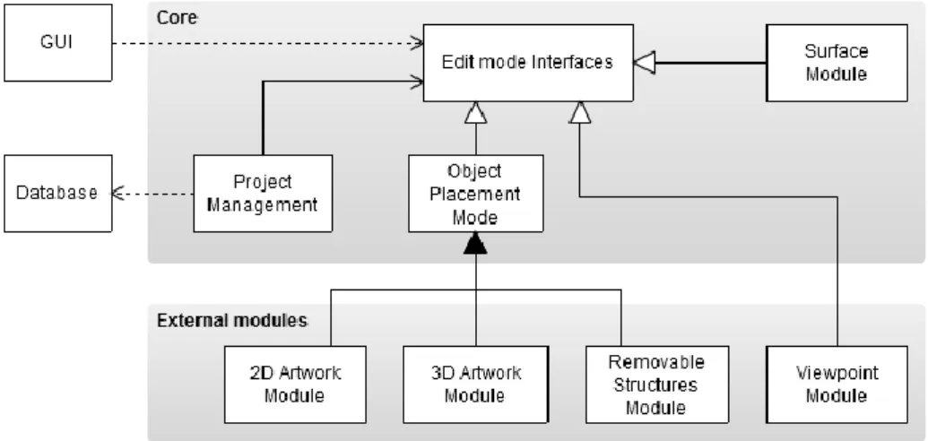
The architecture of the application is based on a modular design so that the supported features can easily be extended, an essential characteristic since the construction of a virtual exhibition may require a wide range of features and objects to expose. Figure 1 shows the articulation between the application components.
Fig. 1. The components of the application.
In order to achieve modularity in the application features, the functionalities of the application are split into multiple edit modes. An edit mode is an independent unit, associated with a specific action that can be undertaken, such as, adding a 2D artwork, adding a 3D artwork, adding a removable structure, creating a viewpoint. It has the capacity to change the scene in some particular way and record these changes on the X3D file that stores the final virtual exhibition. It can be activated and deactivated; and it is possible to switch from one mode to another at any moment, having only one active mode at a time. Its logical state can be recorded and loaded later on when the exhibition is re-edited.
Each edit mode is implemented by an independent module in the application, so that the other components never depend on a module’s specificities. The articulation with each module is done through well defined interfaces (Edit mode interfaces), that contain the necessary methods for the application’s workflow, such as switching edit mode, saving the current logical state or obtaining the graphical user interface associated with the edit mode. Through these interfaces, the components of Project Management can glue everything together without relying on the implemented modules.
Since many features of the application rely on the placement of objects in the scene, there is an abstract implementation of a generic object placement module (Object Placement Mode). This implementation includes all the common features concerning object placement, like initial laying, movement of objects, bounding box drawing, and other generic behaviours of these modules. For each specific type of objects that can be added to the scene, a derived module of this abstract module is implemented, taking into account the particular characteristics of the object. This
abstract module makes the implementation of new objects much easier and also grants consistency of operation across the independent modules.
Information about the artworks is stored in a database integrated into the application, using SQLite. We have chosen an integrated database because it avoids the installation and configuration of servers and databases. Although it would be more interesting to link the application to existing databases, this solution would certainly raise compatibility issues. Moreover, as stated by the experts of the museum, when dealing with the conception of temporary exhibitions, it is a more reasonable approach to use a database separate from the one that contains the museum collection. This solution allows the artists involved and external consultants to access the application’s database without compromising the museum’s database. Furthermore, the artworks displayed in some temporary exhibitions do not belong to the museum’s collection, so it is not supposed to add them to the museum’s database. The information can be added to the database using any tool that handles SQLite databases; the application includes the graphical tool SQLite Studio for this purpose. Alternatively it can be built a graphical tool to provide information insertion in a more user-friendly way, according to the specificities of this type of data.
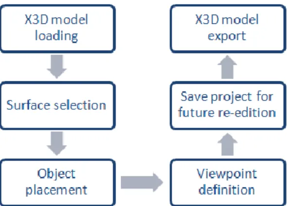
Figure 2 shows a diagram with the elementary steps to build a virtual exhibition. First, an X3D model with the rooms of the exhibition space is loaded. Then the user selects which surfaces are adequate to display artworks and starts object placement. Specific viewpoints can be defined to help navigation around the exhibition. To allow future adjustments in the exhibition built so far, the user can save the current state of the edition. This exhibition can also be exported to an X3D file that can be visualized in an X3D browser.
Fig. 2. Virtual exhibition building workflow
The application is implemented on Java SE 1.6, and the components that work with X3D mainly use Xj3D API, version 2.0M1, which builds and handles the scene graph.
To access and modify the contents of this graph the methods of the SAI (Scene Access Interface), also part of the X3D specification, are used. For convenience we resorted to Java3D API 1.3 for some phases of the geometric processing. The graphical user interface (GUI) is built on Java Swing.
4.2 Standardization of the Scene Geometry
Despite being a well-defined format, X3D allows for multiple internal representations for the same visible result due to the wide variety of nodes that exist to describe the geometry of an object. Such variety allows, for example, that each 3D modeling tool that exports files to the X3D format may use its own conversion process, applying particular techniques and nodes. Thus, analyzing an X3D scene when we do not know its creation process poses major difficulties for interpreting its geometry in an easy, complete and correct way.
Since the application needs to interpret the geometry of the scene and change some of its aspects, for example adding sensors, it became clear that it was necessary to create a layer that abstracts the original geometry of the scene. To overcome this difficulty, we devised a process that does not change the initial description of the scene but adds a new definition of its geometry, which contains the information necessary to add new objects to the scene.
This abstraction layer of the initial scene geometry is composed of a set of surfaces, each surface being a flat area characterized by a single normal vector and comprising an arbitrary number of adjacent triangles. For example, on a building model, one of these areas may correspond to a wall or to the floor.
The process of converting the initial description of the scene into a set of surfaces includes the following steps:
1. Conversion of all the geometry into triangles. This means to convert the description of the scene into a single type of structure based on triangles.
2. Aggregation of triangles on surfaces, combining adjacent triangles whose normal vectors are parallel.
3. Elimination of repeated geometric elements, since the initial X3D file created by modeling software tools may include repeated geometries.
4. Identification of the two sides of every surface, because they can be observed from both sides and a touch sensor can be defined for each side of the same surface.
The conversion of all the geometry into triangles was the process that required a deeper analysis. First, it was necessary to choose a structure based on triangles, among the various possibilities that X3D offers, to serve as the basis for the description of any scene. Taking into account its simplicity and the update possibilities the node TriangleSet has been chosen. In the conversion process, the filters provided by the conversion tool distributed with Xj3D are used to convert the description of the scene into TriangleSet nodes.
Two methods were developed to perform the aggregation of the scene’s triangles into surfaces: a global method and a local method.
In the global method, the surface building process ignores how the geometry is organized in Shape nodes. All triangles of the scene are combined together in one single structure and then the algorithm to aggregate triangles into surfaces is applied. A surface can thus be formed by triangles of different Shape nodes. Note that in this method the process of removing repeated geometries, mentioned above, is unnecessary, because all the repetitions are removed earlier during the combination of the triangles together.
The local method assumes that the shapes defined in the scene represent the logical organization of its geometry. Each Shape is processed independently and the aggregation algorithm is applied only to the set of its triangles. In this case, the
resulting surface cannot be formed by triangles of various Shapes. Therefore, adjacent surfaces, with parallel normal vectors, may be generated.
A rough analysis of the global method shows that it has a quadratic complexity. The local method splits the conversion processing, treating each shape separately. So, considering the number of shapes, its complexity is linear, as it repeats the same algorithm for each shape. Assuming that the number of triangles of each shape is reasonably similar, the whole process has a linear complexity in the number of triangles, which is essential if one wants to render scenes with high complexity. So, despite being more accurate, as it can join together all the triangles of one surface, due to its time complexity, the global method it is not recommend for complex scenes. By default the local method is used, however the user may select the global method.
4.3 Selection of Surfaces
Since all the surfaces of the exhibition building are not usually suitable for the placement of artworks, an important aspect to address is the selection of the appropriate surfaces for this purpose. Before starting the placement of art objects, therefore, the user must choose which areas are suitable for placement. This selection can be interactive, choosing one by one all the suitable surfaces or using pre-defined filters. These filters examine each surface and decide whether it should be selected and can also be combined and used to perform the inverse operation, that is, to reject surfaces instead of selecting them.
The development and integration of new filters are quite straightforward. At the current development stage, these are the implemented filters:
─ Area filter: selects all the surfaces that have a certain minimum area.
─ Normal filter: selects the surfaces whose normal checks the conditions imposed by the user.
These filters can also be used in the surface detection of the scene geometry’s standardization process, enabling performance improvements when dealing with very complex models. The area filter plays an important role here, since it can be used, for example, to rule out the little polygons that define round geometry.
4.4 Placement of Objects
To allow extending the type of objects that can be inserted into the scene, we defined a set of basic parameters that characterize an object: the bounding box; the base of contact with the surface where it is placed; the normal vector of this surface (corresponding to the face or the visible volume of the object); and the orientation of its upper edge.
To simplify the processing stage, it is assumed that the objects - possibly due to a prior processing - have their supporting surface parallel to the XZ plane; the normal to this surface is a vector aligned with the positive YY semi-axis and the orientation of the top line corresponds to the positive XX semi-axis.
Assuming this, it is possible to place any object on any surface by just applying the proper geometric transformations to the object.
After selecting the object to be inserted into the scene, the placement surface must be chosen using the mouse. The centre of the contact surface of the object is placed on the specific surface point selected with the cursor. Then the object position can be
adjusted, applying translations along the surface and rotations. These adjustments are controlled through interface buttons. The object can also be placed on another surface. As mentioned above, each type of object is implemented by a corresponding module which reflects its specificities. 2D artworks are stored as images in the database, along with additional information about the piece. When such an object is placed on a scene surface, a parallelepiped is created to represent the object, and the corresponding image is applied as a texture on one of its faces.
One of the characteristics stored in the database is the physical dimensions of the artworks, so they are displayed using the correct scale.
3D artworks are stored as X3D models, and their orientation in space must comply with the rules described above. The bounding boxes are automatically calculated according to their geometry and saved in the database to avoid further unnecessary processing. To this end, the initial model is transformed into a description that contains only nodes with explicit coordinates, and a search is performed on these coordinates to obtain the extremes of the bounding box. When a 3D object is inserted into the scene, the X3D nodes that describe it are added to the scene.
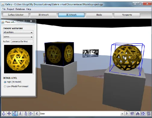
Fig. 3. Two alternative representations of the same 3D object are shown.
An alternative means for placing 3D artworks is achieved by using a simplified representation. It is built taking into account the smallest axis aligned bounding box that can be adjusted to an artwork’s model and a single image of the artwork. The image is stored in the database along with the physical dimensions of the object, which can also be calculated from the corresponding 3D model if it exists. A
parallelepiped object is placed in the scene, having the correct dimensions, and the image applied as texture to all faces. In Figure 3 there is an example of two different representations of the same 3D object.
4.5 X3D Exhibition File Generation
The X3D file containing the description of the virtual exhibition is produced using an exporting process, since Xj3D does not possess such conversion capacity. The file containing the original scene graph is modified using the DOM (Document Object Model) interface provided by Java API for XML processing.
To maintain the modularity, each module is responsible for defining the changes in the XML document that reflect changes made in its context, that is, in the corresponding edit mode. Any X3D browser can be used for this purpose.
4.6 Exhibition Re-Edition
To make adjustments to a virtual exhibition previously built, the X3D file resulting from its construction does not have all the required information. Hence it is necessary to know which objects were introduced in the initial scene.
To enable the re-editing of virtual exhibitions, a mechanism was designed based on a set of auxiliary data structures that store information about all objects added to the scene.
The contents of these structures can be saved in a file - called the state file - which reflects the current editing state of a scene.
Later, to re-edit a virtual exhibition, its state file is used to restore the contents of the auxiliary structures that manage scene changes, allowing updates to the scene.
This process also keeps modularity, each editing mode being responsible for saving and restoring its own status.
4.7 User Interface
Several adjustments were introduced in the user interface after the preliminary evaluation to provide a clearer identification of the available functionalities.
The user interface is composed of two sets of elements: one is shared by all edit modes while the other depends on the active edit mode.
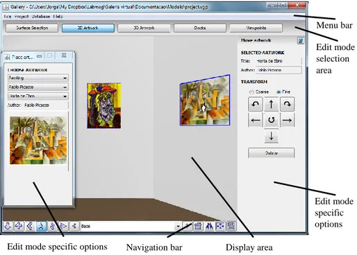
The shared elements are split into three different zones (Figure 4): (1) the menu bar, with common options like file save and file load; (2) the edit mode selection area, bellow the menu bar, comprising a set of buttons that activate the corresponding edit mode and (3) the 3D browser, including the display area and the navigation bar.
The edit mode dependent options are displayed in two lateral panels, one on each side of the 3D browser, as shown in Figure 4, corresponding to the placement of 2D artworks. In order to maximize the 3D browser display area, these panels are narrow and completely hidden if there are no options to show. Furthermore, each panel can be detached from the main window generating separate always-on-top windows which can be minimized, thus allowing the browser to expand to both sides. These features of the interface can be observed in Figure 4, in which the left panel is detached from the main window and in Figure 3 in which the right panel is minimized. The content of these panels is defined by the active edit mode. In the
implemented edit modes, the left panel is used for definition or placement of new elements in the scene, while the right panel provides options to deal with existing ones.
Fig. 4. User interface for 2D object placement.
Regarding the interaction with the 3D scene, there are many features shared by all the edit modes related to objects’ placement, namely:
─ The elected surfaces for objects’ placement become highlighted and selectable when the cursor is over them.
─ To place a new object in the scene, the user clicks in a selectable surface and the object is placed in that point.
─ The objects placed in the scene that correspond to the active edit mode, become slightly highlighted and selectable. When the cursor is over them, they are visually enhanced by displaying the corresponding bounding box.
─ Only one object can be selected at a time. It is possible to move an object from one surface to another by selecting it and clicking in any other selectable surface.
The edit modes related to objects’ placement also share options to move, rotate and delete the selected object. These options are located in the right panel and only become enabled when some object is selected.
The navigation in the 3D scene is achieved through the navigation modes and options offered by the Xj3D Browser.
The specific details of the interface for each edit mode are presented, as follows: Menu bar Edit mode selection area Display area Navigation bar
Edit mode specific options
Edit mode specific options
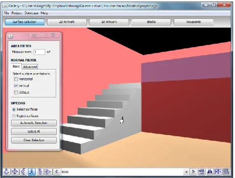
Selection of surfaces
This edit mode provides a simple interface to configure the filters for the selection of appropriate surfaces to dispose artworks as described above (Figure 5). Whenever a surface is selected, its colour becomes more reddish to stand out.
Fig. 5. User interface for the selection of surfaces appropriate for the placement of objects.
Placement of 2D artworks
This edit mode supports the placement of two-dimensional artworks on surfaces. Its interface contains the functionalities for searching the database of artworks (Figure 4). A thumbnail of the chosen artwork is displayed. When an artwork is selected in the scene, the right panel displays the title and author of that artwork.
Placement of 3D artworks
This edit mode deals with the placement of three-dimensional artworks. Its interface (Figure 3) is similar to the previous one. Additionally, it allows the selection of the level of detail to be used for the artwork’s representation. Only the available levels of detail of the chosen artwork are enabled.
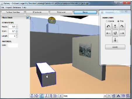
Placement of removable structures
This edit mode allows the placement of parallelepiped objects designed to support the display of artworks. It is selected by clicking on the button “Block” of the edit mode selection area. It provides basic options to choose the dimensions of the parallelepiped objects and to select their colour through a standard colour chooser (Figure 6).
Fig. 6. User interface for the placement of removable structures
Viewpoint definition
When this edit mode is active, the left panel provides options to define new viewpoints and select existing ones (Figure 7). When a viewpoint is selected, the right panel displays options for redefining it.
5
Conclusions and Future Work
We have presented a tool - Virtual Exhibition Builder - for building a virtual exhibition interactively. This tool aims to assist museum teams in the initial stages of mounting an exhibition. In addition, the resulting virtual exhibition can be shown through the Web for purposes of diffusion.
The development of this tool received input from the experience gained in a previous work and was designed in order to overcome its limitations. This tool was presented to specialists from a museum and several improvements were introduced afterwards.
The actual tool comprises mechanisms for reading any scenario described in X3D, editing virtual exhibitions already assembled, displacing 2D and 3D artworks and also removable structures that support the display of artworks.
The modular structure of the tool allows the addition of new features by joining new modules concerning both the work needed to mount an exhibition and the creation of virtual exhibitions to show throughout the Web.
Future developments include the creation of printed layouts of the surfaces, with artworks annotated with the distances between them and the floor; the placement of objects suspended from an application point; the ability to change the colour of the exhibition surfaces; the projection of videos on surfaces; the reproduction of music depending on the site that is being viewed at the time; the capability of displaying in the scene details from the selected artworks, such as title and author, in order to provide more information to visitors at the virtual exhibition. As the users of this tool are not necessarily specialists in informatics, an application specific interface that supports the insertion of objects in the artwork database should also be developed.
The team of the museum proved very receptive to the use the Virtual Exhibition Builder as a work tool to mount a new exhibition in a building that is currently under repair. We intend to follow closely the preparation of this exhibition and improve the tool accordingly with the result of this experience.
Acknowledgements
This work was funded by a grant from the Foundation Amadeu Dias (University of Lisbon). We would like to thank to Dr. Ana Cristina Leite, director of the City Museum of Lisbon Town Council, and her team for the valuable recommendations and suggestions.
References
Baylyl Art Museum, University of Virginia,
http://www2.lib.virginia.edu/artsandmedia/artmuseum/docs/virtual.html (Last access 15-7-2011)
Chen, S. E. 1995. QuickTime VR – An Image-Based Approach to Virtual Environment
Navigation. SIGGRAPH’95, pp 29-38.
El-Hakim, S., MacDonald, G., Lapointe, J.-F., Gonzo, L., Jemtrud, M. 2006. On the Digital
Reconstruction and Interactive Presentation of Heritage Sites through Time. Proceedings of
the 7th International Symposium on Virtual Reality, Archaelogy and Cultural Heritage, (VAST’06) pp 243-250.
Google Art Project, http://www.googleartproject.com (Last access 15-7-2011)
Gomes, J.C., Carmo, M.B., Cláudio, A.P. 2010. Construção Interactiva de Exposições Virtuais, INFORUM 2010 Simposium de Informática, in Portuguese, pp. 305-316.
Gomes, J.C., Carmo, M.B., Cláudio, A.P. 2011. Virtual Exhibition Builder. Proceedings of the International Conference on Computer Graphics Theory and Applications (GRAPP 2011), pp 330-333.
Hetherington, R., Farrimond, B., Presland, S. 2006. Information rich temporal virtual models
using X3D. Computers & Graphics, Vol. 30 (2), pp. 287-298.
Hrk, S. 2001. Virtual Art Gallery. Proceedings of the 5th Central European Seminar on Computer Graphics, pp 185-194.
Katalabs, http://www.katalabs.com/blog/ (Last access 9-11-2010)
Louvre Museum, Paris, http://musee.louvre.fr/visite-louvre/index.html (Last access 15-7-2011) National Gallery of Art, Washington,
http://www.nga.gov/exhibitions/calder/realsp/roomenter-foyer.htm (Last access 15-7-2011)
Patias, P., Chrysantou, Y., Sylaiou, S., Georgiadis, Ch., Michail, D. M., Stylianidis, S. 2008.
The Development of an E-Museum for Contemporary Arts. Conference on Virtual Systems
and Multimedia 2008, pp 20-25.
Ramic-Brkic, B., Karkin, Z., Sadzak, A., Selimovic, D., Rizvic, S. 2009. Augmented Real-Time
Virtual Environment of the Church of the Holy Trinity in Mostar, Proceedings of the 10th
International Symposium on Virtual Reality, Archaeology and Intelligent Cultural Heritage (VAST’09), pp 141-148.
Semião, P. M., Carmo, M. B. 2008. Virtual Art Gallery Tool, Proceedings of the International Conference on Computer Graphics Theory and Applications (GRAPP 2008), pp 471-476. Victoria - A virtual gallery from Victoria and Albert Museum, London,
http://www.arco-web.org/Virtual/dresses.php (Last access 9-7-2010)
Vlahakis, V., Ioannidis, N., Karigiannis, J., Tsotros, M., Gounaris, M. 2002. Virtual Reality and
Information Technology for Archaeological Site Promotion, Proceedings of 5th International
Conference on Business Information Systems (BIS’02), pp 24-25
Walczak, K., Cellary, W., White, M. 2006. Virtual Museum Exhibitions, IEEE Computer, Vol. 39 (3), pp 93-95.
Web 3D, http://www.web3d.org/ (Last access 15-7-2011)
Wojciechowski, R., Walczack, K, White, M., Cellary, W. 2004. Building Virtual and
Augmented Reality Museum Exhibitions, Proceedings of 3D Web Tecnology 2004, pp