A Cognitive Walkthrough towards an Interface Model for
Shape Grammar Implementations
Joana Tching
1,*, Joaquim Reis
1, Alexandra Paio
2 1Department of Computer Science and Information Technologies, ISCTE- University Institute of Lisbon, Portugal
2Department of Architecture, ISCTE- University Institute of Lisbon, Portugal
Copyright©2016 by authors, all rights reserved. Authors agree that this article remains permanently open access under the terms of the Creative Commons Attribution License 4.0 International License
Abstract
The present study arises from the interest in computing as an important partner in the design process and the new paradigms in design practice that emerge with the use of computation. Shape Grammars (SG) are an example of ruled-based systems that, used in applications in the field of computational creativity, might assist architects, designers and artists in the creative process, not only creating solutions but also as a way of developing new ideas. However, SG applications developed so far developed so far address neither the specific work of creative projects nor the computational knowledge and habits of the designers-in-general. With this in mind, this research intends to reveal our proposal of IM-sgi (the initials IM stand for Interface Model and sgi for shape grammar implementations), a model of interface for SG implementations that can help SG to be introduced in the project practice, as this is not a reality yet and could mean a great contribution for new creative and complex architectural and design projects. This paper presents the description of the analysis used to define the IM-sgi model, with the result of a Cognitive Walkthrough (CW) made to a group of SG implementations and with the interaction model of Scott Chase [1] as the basis to define the users and how they communicate with the SG implementation.Keywords
Shape Grammars, Computational Design, Computational Creativity, Interface Design1. Introduction
The present paper has the purpose of presenting our investigation in the field of SG and our creation of an interface model for SG Implementations. It is organized in four chapters, Introduction, Methodology, Results and Conclusion
After a brief introduction to our investigation and its objectives, we present the Methodology applied to understand the existing SG implementations and which ones seem to answer the interaction dynamics we believe are needed for the user to understand SG potential when used in creative projects. This was made using a CG to a group of
selected SG implementations, which were available for manipulation, to be able to analyze the interaction modes that are already available for SG use.
We then show the results of this CW and the conclusions we were able to achieve.
The computational use of SG is the main field of study of this work, which has the main objective of taking SG to the design practice. We believe that SG can bring computational creativity to architectural, design and artistic projects, if used in computational implementations that are well received by the professionals of these areas. Thus, SG can widely extend the study of different creative solutions and be a partner in creative decisions and proposals. Digital design and CAD applications are widely used nowadays in architectural projects and design. In creative areas, computational applications have meant much more than faster and more effective processes, comparing to those previously done. They have also allowed the production of more complex and ambitious projects, offering new ways of analysis, control and representation, which would not be otherwise available to designers, as more time and unaffordable resources would be required.
Architectural design, in contrast to other artistic areas, develops in different stages. These stages arise from the need to solve a large number of issues, but also from the existing rules and constraints to be complied, legal, environmental, economic, aesthetical or other. The resolution of all these constrains defines the final project outcome and the architect demonstrates his creativity with his resolution of all the involved issues in an aesthetic and functional product. By dividing the project into its elementary parts, we can see that the architect elects, consciously or intuitively, a set of rules and makes choices that generate the final work.
There is a wide range of situations which are common to the majority of the architectural projects and even the specific issues of each project can be dealt with the use of SG [2]. This is the reason why SG can explain design styles, once the rules, which generate a certain shape, are recognized. Overall, the architect’s intentions are translated by rules, which are imposed by technical and legal needs of the project and by the artist’s aesthetic and creative intentions. Through the definition of a set of rules that
combine the technical and creative purposes of the architect, SG can form a wide range of solutions that enhance the creative response to a problem. Computational applications that use SG can give the architect creative responses that he would not achieve in other way.
Nowadays it is common practice to use computational applications, which reproduce the architect’s manual design, among other technical aspects of the project (such as automatic measurements, thermal simulations, three-dimensional visualization, etc.). Similarly, we believe that the next step is the use of SG in the common practice. This new way of working is a way of optimizing ideas, using not only computational design but also computational creativity.
Thus, how to achieve good usability? According to Myers, there are 3 main points. First, know the users and their tasks, through the analysis of these and contextualized investigations; Second, ensure the adequacy of the design through prototypes, tested by users with participatory and iterative design; Third, making the final product usable and efficient through the use of the interface, analyzing it through various methods, heuristics, and others [3]. The user interface (UI) is whatever the user finds in a computer application, namely: functionality, content, labels, presentation, layout, and navigation, speed of response, documentation and help, among other. There are several difficulties in defining the UI of an application. The design of the UI is a creative process and often designers have difficulty thinking how end users. Usability is linked to learning, efficiency, productivity, ease of memorization, no errors and satisfaction. Good usability is important, as it reflects the notion of quality the user experiences when using the computational application. Good usability allows beginners to become effective more quickly, experts to be more efficient, to reduce errors, the true needs to be identified and for the computational application to be successful on the market [3].
The importance and complexity of the user interface, meaning the direct connection between user and application, is so great that today there is a widespread use of toolkits, Interface Builders and even components architectures.
Ultimately, a computer application is created for the function to be performed and the functionality of a computer application is defined by the set of tasks that it provides to its users [4]. The importance of computer applications is visible when it is used efficiently by the user that is the computational application usability allows the users to meet their objectives.
2. Methodology
For SG to have real potential of use, there is the need of understanding how the users apply and manipulate SG and their results. The model of interaction between SG and the user developed by Scott Chase [1] is a very good example of the studies on this matter. This model addresses computational implementation of SG and how they must
respond to the users’ needs and objectives when using them. But analyzing this and other models, there seems to be a lack of guiding lines for an unambiguous interface for SG implementations that fulfill the objectives of the existing models of interaction, already addressing a large number of issues about the needs of the SG users. The interface is the main means of communication between the user and the SG implementation. When this communication is not well addressed, the efficient use of the SG implementation is compromised and the problem solutions that could be generated are unlikely to happen.
To study the issues about the interface, one must primarily understand the type of users that are being addressed. Our main interest is on the use of SG implementations on the design practice.
The interface of a SG implementation, with the design practice in sight as we intend to, must take into account that architects are trained and feel comfortable using CAD software, which interface is well adopted and stabilized. The complexity of CAD systems and the type of tasks associated impose a high-quality interface. In this sense, the best way to insure that a SG implementation is well accepted and understood by an architect is to apply the basics that the final user is adapted to.
Thus, our proposal is the creation of IM-sgi, an interface model that intends to respond to computing ergonomics and suitability of architects needs that SG implementations should respond. This model also takes into account other types of users of SG, as designers, artists and students.
This model is being conceived with Human-Computer Interaction (HCI) methods, with focus on the ones of Interactive Design (ID) [5].
IM-sgi is our proposal to make the bridge between user and SG implementation leading SG to the project practice and leaving the analytical and educational fields where they have mainly been used.
For this to take place there is a gap that needs to be addressed: make the SG implementations clear and simple, through a user directed interface. The answer to this problem is a model of interface that reports the user needs. Following this need it is developed an IM-sgi interface model for SG implementations.
2.1. User Groups and Interface Needs
IM-sgi is based on the analysis of the Interaction model of Scott Chase [1] that addresses the types of users for SG and their way of relating to SG implementations. Chase’s model of interaction opens the chance for combination with a model for the Interface of SG implementations. The interface has great importance for the success of SG implementations, as it allows the connection of the computational tool to the goal to accomplish with it.
According to Chase, there are several possible scenarios for the control of SG implementations. The author believes that there are three distinct entities: The creator of the system, the designer and the computer.
Figure 1. Control scenarios for the development of Shape Grammar implementations [1]
The scenarios vary the level of control of each of these three entities can control range from being totally user side computer or entirely on the side. So, with the focus on the user, the user may have full control, partial (sharing of the control with the other two entities) or none.
Thus, studying the Scott Chase control scenarios and with the perspective of SG use in creative projects, we identified three main groups of users who relate directly with a level of control scenario. As we have different purposes, our groups differ from Chase’s groups. Instead of focusing in the control, we focus on SG expertise. Instead of Developer; Designer and Computer, our three groups are: Students - users that use SG in an exploratory
manner with the purpose of learning or simple experimentation, which corresponds to Chase’ scenario 4 (the user only selects pre-existing elements);
Designers/Artists - users that apply SG for creative projects, more simply or elaborately as needed or according to their SG knowledge, corresponding to Chase’ scenarios 2 and 3, where the user can create and manipulate shapes and rules;
Experts in SG - users with the ability to explore all areas of the SG and their computer implementations, which corresponds to Chase’ scenario 1, where the user can control the entire implementation, including its code.
Scenarios 5 and 6, where the computer system has full control of events and only allows the user to be a spectator
of results, without any intervention, were excluded from this study since they fall outside of the scope of studying how to use SG in creative projects.
For each of these groups the interface should behave distinctly, as the level of manipulation of SG, either in the side of shapes or the rules, or both, is different.
The most basic use is more directed to the shape handling. In the opposite direction, the greater the knowledge and specific objective, the biggest is the focuses on rules manipulation.
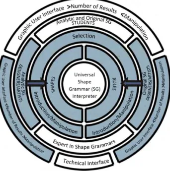
For a better definition of the stated above, a circular scheme is presented, reflecting the various possibilities for manipulation and control of SG implementations according to these three groups. This scheme considers valid options both for analytical and original SG.
This circular scheme must be read as follows: each circumference section relates to the following inner and out circumference sections that “touch” it. On the other hand, the central axes of each section refer to the most complex action possible for each user group.
The schematic representation of the relationships between users and the interface was done in a circular diagram in order to symbolize the various layers of information involved. We can verify that the core is the universal SG interpreter and that the outermost layer is the interface. Among these layers we have, from the inside to the outside, the generating elements of SG (shapes and rules), how these elements are worked (selection, introduction / manipulation) and the user groups.
Figure 2. Scheme of relations between users and IM-sgi interface model
The outer layer defines which type of interface is more adequate to each group (Graphical User Interface or Technical Interface). It also defines if we should have more or less number of results and ability to manipulate, with the signals “>” and “>”.
In this diagram it is also introduced a symbology that allows us to see the level of control that each user group has When analyzing a specific user group section, the outer layer that connects to it describes the characterization of the interface for that group, in the aspects of manipulation and results, and the inner layers reflect how the user manipulates Shapes and Rules to create SG.
For better understanding, next is presented the same scheme, but with the illustration of the several possible readings, one for each user group.
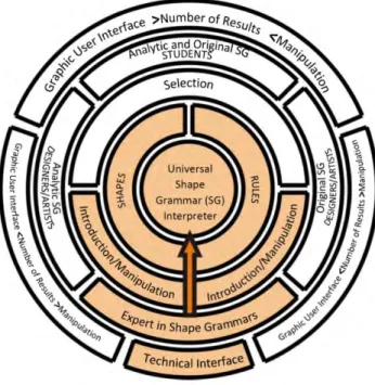
For better understanding, below Fig. 3, 4 and 5 illustrate the depth of control for each group of users, illustrating with color the segments that correlate for each group. Most basic users (Students) have no direct access to anything but the immediately following layer (Fig.3) Intermediate users (Designers/Artists) can skip a layer and directly manipulate “deeper” elements (Fig. 4). Finally, expert users (Experts in SG) can skip all layers and directly manipulate the core.
The segmentation of users is not related to the creation of limitations, it is related to the adjustment of the interface accordingly to user's needs. This premise allows the interface to be evolutionary and show levels of complexity according to the tasks that user groups perform. This adaptation allows the same computational application to communicate differently and adjusted to each group of SG users identified in this proposal.
Figure 3. Interaction scheme for "Students" group
In the above diagram it is indicated the type of interface that is set to "Students", the most basic of the three, focused on the use of SG in a perspective of learning and exploration. This interface is intended to allow the selection of pre-existing shapes and rules, already existing in the computational application, so that the users can easily learn and understand how they relate and create solutions. With this purpose, the interface must have a greater number of results and less possibilities of manipulation.
Fig. 4 illustrates the type of interface set to "Designers/Artists" group, which is considered the intermediate mode regarding the knowledge level and need for SG manipulation.
In the outermost layer it can be seen that the interface needs to present a smaller quantity of results and shall permit greater manipulation. At this level, Shapes and Rules can be created by the user, as preexisting ones may not fill all his needs.
Reading this diagram from the left side, users can handle the application for Analytical SG, focusing on the Shapes, and reading from the right, users can manipulate the application for Original SG requiring handling the Rules. For both the Shapes and Rules, it remains possible to work only by selection, as in the most basic mode of interaction.
This is the privileged interface for users that can use SG implementations for real architectural, design or artistic projects. It requires a certain level of SG knowledge and that’s why it is on the center of the scheme, as we can consider it the one that would answer to the objectives of our research – the use of SG in creative projects.
Figure 5. Interaction scheme for “Experts” group
Fig. 5 illustrates the type of interface set to "Experts of SG" group, which is considered the expert mode regarding the knowledge level of SG and programming knowledge. These users are considered to be able to manipulate the universal SG interpreter so that they can expand the implementation abilities and range of solutions.
In the creation of a computer application, the interface is a time consuming task and, frequently, the programmer, or program designer, is not familiar with the true needs and limitations of the end user. A model that specifies categories of users of SG and their objectives, that clarifies how each type of user makes use of the SG and what
barriers of communication need to be addressed increases the possibilities of success of use of SG implementations.
2.2. IM-sgi: Towards an Interface Model for Shape Grammar Implementations
With the difficulty associated to the creation of SG implementations, it is possible that the user interface issue has not received the deserved attention, when it plays a major role in the success of the computer application.
IM-sgi main goal is the development of a friendly interface model for SG that gives a response to the existing communication failure between the user and the tool. Thus, to address this problem the research used the following methodology divided in 3 main phases.
Phase 1 is the preliminary analysis of the existing implementations of Shape Grammars, with focus on their interface. This analysis allows us to understand the types of interaction that have been already used and tested and understand their strengths and weak points.
Phase 2 is the definition of IM-sgi, structuring the model of interface according to the types of users and their interaction with the system, according to their different goals. This model has its roots in the Interaction Model of Scott Chase [1], as the author identifies the ways that designers can interact with SG and how they relate with an SG implementation. IM-sgi intends to connect these interaction definitions and the application functioning, as the interface is the means of communication between user and machine.
Phase 3 is the creation of a prototype that follows the IM-sgi guide lines so we can test its usefulness and response to the issues addressed. This paper presents the Phase 1 of the IM-sgi definition. As stated above, for a systematization of the IM-sgi fundamentals, the first step to be taken is a thorough analysis of the existing SG implementations. Thereby, it is intended to understand how the interface issues have been approached by these implementations and which considerations may be made from them, in terms of suitability to the user and performed tasks.
This analysis, with the goal of gathering conclusions that enable the proposal of an interface model settles on Human Computer Interaction (HCI) methods, selected according to the objectives of this paper. Since this discipline studies interface designs, it is the one that can guide this process by the most adequate principles.
When addressing the usability of existing SG implementations, excluding the analysis of their capability of application in the creative project (which is the motivation for the present study), we realize that there is no pattern in the fulfillment of HCI parameters, as a common type of interface or a common communication logic does not exist, even when the results are similar.
There are various HCI techniques for rating interfaces, which can be applied to the intended analysis, thus it is very important to decide which one helps us achieve the
expected conclusions in the most expeditious manner. A set of techniques called Inspection Methods are considered relevant to this study. They are analytical techniques which allow the evaluation of the usability [6], that is, they refer to the evaluation of how easy to learn users think a given application is, the efficiency utilizing it after learning it, and whether the use of the application is enjoyable. The importance of the usability and methods to assure the same have earned great notability after the 1990`s. The major argument to the new introduced methods was the search for methods that would involve less costs, since the tests of usability are efficient, but in general, very expensive. The use of inspection methods brought the urge to control costs, which allowed the obtaining of results in a way that was more rapid and economic than empirical techniques, which involved user-applied usability tests, thus supporting in the revision and analysis brought off by experts.
Since the analytical techniques of the inspection methods do not directly involve the users, they are based on the observation and analysis of actions that the users execute and the results they expect. For a preliminary analysis of the usability of the existing tools, these were the methods considered the most adequate. Testing with users offers excellent opportunity to observe how well adapted is the interface to the user’s workplace; however, for the preliminary analysis of the existing tools, it would cost a time/manpower investment, which does not seem to be the most recommended for the desired results. Tests with users can indeed be of a great importance for the validation of the effectiveness of the IM-sgi, which will be developed in further work.
The vast majority of the interfaces are analyzed through techniques that require expertise in the area of UI. Examples of these techniques are the usability tests and the heuristic evaluation. However, these techniques have several limitations, once it is not always possible to have specialists with the adequate background to carry out the analysis. These techniques are also hard to make use of before the interface is finalized, which requires the results to be verified in an advanced phase, when it may be no longer possible to implement major alterations [7], therefore not being suitable for the outline of the proposed interface model.
We intended, thus, to apply an Inspection Method, which did not demand a UI specialist or tests with users. Within these parameters, noteworthy is the method of Cognitive Walkthrough (CW) proposed by [8], which is a formalization of the possible thoughts and actions of a user while interacting with the interface. This method emerges from the adaption of Design Walkthrough techniques used in Software Engineering, which involved manually testing code sections to proof determined functionalities, with cognitive models of learning by exploration. With the CW the intention is to test the user’s cognitive activities manually, with the purpose of analyzing how they are able to learn to perform the tasks that the system supports, based on the learning by exploration theory.
The CW method has evolved over the time and various versions have been put together by several authors [9], resulting in a successful and basic principle to simulate the cognitive behavior of the user through the responses to learning-related questions, manipulation and adoption of the analyzed application.
In short, the CW enables the evaluation of the ease with which the user completes a task with very little system knowledge and the ease of learning and exploring the interface.
In order to make this rating possible it is necessary to set up an action script that reflects the manipulation and the application by the user to achieve a certain goal. This process shall be put to work when the application is still to be developed, aiming the correction of determined aspects, or it may be utilized after the application is already developed, to determine the difficulties in the use of the system to run determined scenarios.
As the purpose of the preliminary analysis of existing SG is its usability, considering that this aspect directly relates to the possible adoption of the SG by the designers, this technique allows the perception of the relationship between user and application in the features that are relevant to the intended results, that is, in the ease of handling and use of SG.
2.3. Phase 1: Cognitive Walkthrough Process Organization
For an observation to the existing SG implementations, that enable a critical analysis of the interfaces that these possess, this chapter presents a comparative survey with the implementations that could be performed and tested. Since the key point to the analysis is the communication between user and the computational tool, the simple theoretical review of the functioning of the application or the image of the interface has not been considered adequate for this study. This premise is also essential for the correct use of the CW, which usage can only be taken into account when the handling of the application is possible.
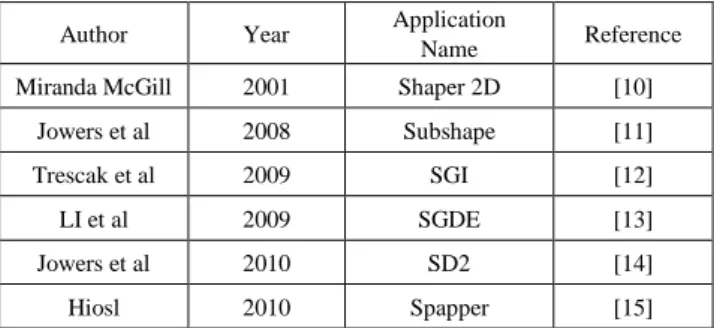
In accordance to the SG implementations studied here, the present analysis was performed by comparatively testing the following implementations, organized chronologically (Table 1).
Table 1. List of the applications used for the preliminary analysis of SG
implementations
Author Year Application
Name Reference
Miranda McGill 2001 Shaper 2D [10]
Jowers et al 2008 Subshape [11]
Trescak et al 2009 SGI [12]
LI et al 2009 SGDE [13]
Jowers et al 2010 SD2 [14]
Hiosl 2010 Spapper [15]
been gathered, the process of the CW development was followed to evaluate the interface in the context of specific user-performed tasks. The CW session is formed by the description of the interface design, it is considered an action scenario, a user profile and, at last, a sequence of actions that the user must successfully perform in order to complete the desired task [16].
The CG process performed is made by a series of definitions, preliminary analyses and, finally, application of the method itself, that is, the effective testing of SG applications.
The description of the process is presented next, with a summary of the information and results. The analysis of the selected SG implementations was made accordingly to four steps: (1). Considered users; (2) Tasks for evaluation; (3) Preliminary Analysis; (4) Development of Cognitive Walkthrough.
The first step is the section of users that can give us a wider range of aspects to analyze. From the groups pf users defined above (Students; Designers/Artists and Experts in SG) we defined that the ones to be considered are the Designers/Artists. This choice allows us to consider the users that use computational tools of vectorial and non-vectorial drawing in their professional practice.
The second step is the definitions of the main tasks the users can perform, defining a hierarchy of tasks for evaluation. These are the tasks that will guide de CW, meaning they are the ones to be used in step 4. We defined 5 tasks that sum the steps the users take to create and use a SG:
1. Creation of shapes 2. Creation of rules 3. SG Application
4. Manipulation of SG-obtained solutions 5. SG Alterations
The third step is the Preliminary Analysis, when it is gathered and registered information considered relevant to the analysis, through a list of important aspects to scope: 1. General Analysis (Table 2)
1.1. Type of Interface – if graphic or not
1.2. Dimensions – if SG are two-dimensional or tridimensional, or both
1.3. First impression – analysis of the impact in the first visualization of the general interface of the application
1.4. Learning – analysis of the ease of the tool manipulation, if fast or slow, if difficult or easy without script (this analysis was performed according to the actual work processes of the designers, that is, verifying the resemblance of the work with the computer-assisted drawing applications, which are commonly utilized by this group of users)
1.5. Graphics – graphical resemblance analysis with the generality of the computer-assisted drawing applications
2. Usability analysis in accordance to the (ISO 9241-210, 2010) which defines the ergonomic principles of the dialog between humans and information systems, allowing to qualify the experience of the user when performing the tasks defined above, these being (Table 3):
2.1.1. Suitability to the task 2.1.2. Ease of learning
2.1.3. Suitability to the individualization 2.1.4. Accordance with user’s expectations 2.1.5. Self-descriptive
2.1.6. Controllability 2.1.7. Error tolerance
Following the (ISO 9241-210, 2010), which defines the scope of efficiency, satisfaction and effectiveness, this analysis was performed using a rating scale of 5 points according to the level of efficiency. According to this standard, efficiency refers to the resources used by the user to ensure the successful completion of a task. In the performed CW, we measure the time taken to perform a task, reflecting the ease of interpretation of the interface and whether it was necessary to use the manual after failure to solve the task. Thus, the outline evaluation scale used is:
1. Without success in meeting 2. With great difficulty 3. With some difficulty 4. Easily
5. Very easily
This analysis was made joining complementary information found in referred bibliography in order to obtain a broader perspective of the selected implementations (MCKAY, et al., 2010).
Step four is the Development of the Cognitive Walkthrough, performing the analysis of the selected implementations according to the usability test with predefined tasks.
In the next chapters, we describe our Cognitive Walkthrough and the conclusions we gathered from the testing of the SG computational applications available for public use.
2.4. Phase 1_Step 3 – Preliminary Analysis
After the definitions from step 1 and 2, step 3 is the preliminary test to the SG implementations selected, to gather information about the implementations that are to be used in the Cognitive Walkthrough (Table 2).
The next tables resume how the SG implementation allows performing the tasks defined for the Cognitive Walkthrough and their level of performance according to Dialogue Principles of (ISO 9241-210, 2010) (Table 3 and 4).
Table 2. Preliminary Analysis to the selected SG implementations
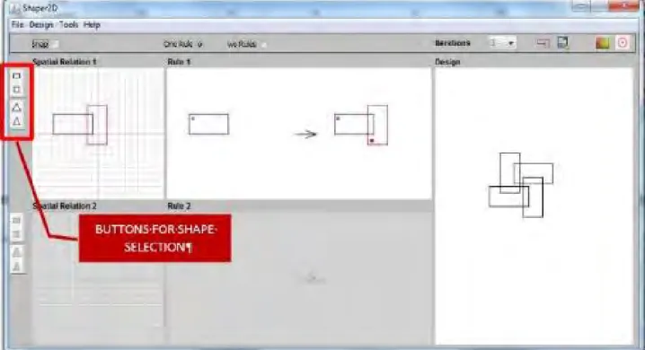
Figure 6. Shape Drawing (from: Shaper 2D)
2.5. Phase 1_Step 4 - Development of the Cognitive Walkthrough
The CG is here presented for each SG implementation showing, for each one the 5 tasks to be performed in the CG, a description and an illustration picture for each one. 2.5.1. Shaper 2D [10])
In 2001, Miranda McGill presented 2D Shaper, a visual dynamic tool for use Shape grammars [10]. The purpose of 2D Shaper is the exploration of two-dimensional basic SG in a learning perspective, and aiming the understanding of the potential use of computer-based SG in the design area.
Task 1 - Shape creation
The pre-existing shapes are only selected and are displayed as buttons on the left side of the display. We can select the initial form and the form to which the rule is applied to (Fig 6).
Task 2 - Rule creation and Task 3 - SG application
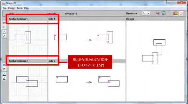
Rules are created "invisibly" to the user, which only moves the shapes being submitted. Immediately and automatically the result of both the rule and the final shape created are shown.
The user can select the number of rule iterations and can also choose to apply between one or two rules at a time (Fig. 7).
Figure 7. Rule creation and results visualization (from: Shaper 2D)
Task 4 - Solutions manipulation
The manipulation of the solutions is performed by changing the number of iterations through a dropdown menu that allows choosing between 1 and 25 iterations (Fig 8).
Figure 8. Choice of rule iterations (from: Shaper 2D)
Task 5 - SG modification
Changes in the SG are performed in a simple and immediate way, by manipulating the position of the shapes, or by changing the initial shape and the shape to which the rule is applied to.
2.5.2. Subshape [11]
Subshape was created with the purpose of creating a SG implementation based in visual correspondence. The author used the Hausdorff distance, which is a measure of the maximum distance from a set of points to the nearest point in a second set. Unlike any other SG implementation, this one works with bitmapped images.
Task 1 - Shape creation
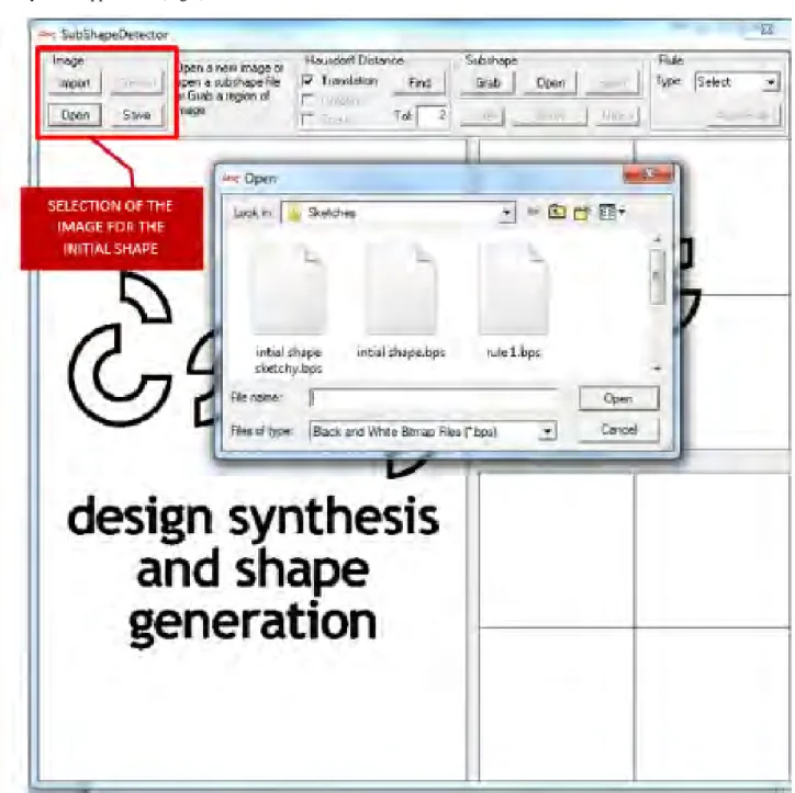
Initial shapes are obtained by importing the bmp format image files, or directly opening an image files in black and white (bps). We cannot draw directly in the application. When importing bmp images, we need to convert into bps, which is done directly in the application (Fig 9).
Figure 9. Bitmaps as initial shapes (from: Subshape)
Task 2 - Rule creation
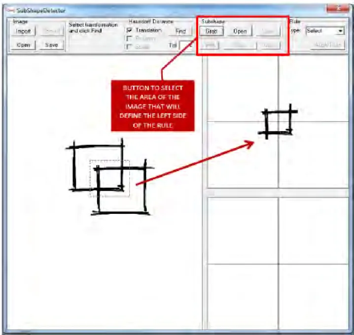
The application only allows the use of a substitution rule and for it to work it is necessary to follow exact the steps, or it crashes. This could be a problem that only happens in the published version of the application. In order to define the left side of the rule, we can open a bpm file through the Subshape menu, or the left side can be obtained by selecting an area of the initial shape by using the Grab command in the same menu (Fig. 10).
Figure 10. Left side shape creation through selection of an area (from: Subshape)
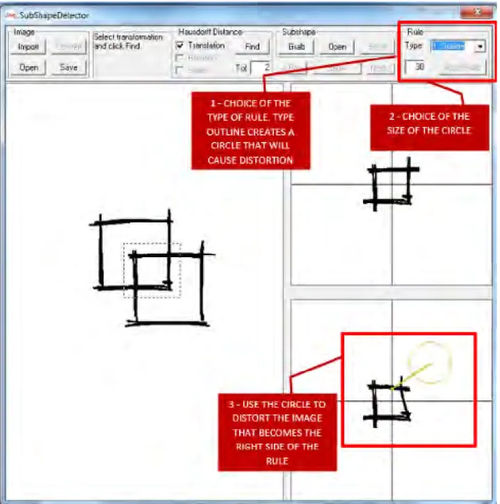
After selecting the shape of the left side of the rule, we can choose in the dropdown list how to create the shape of the right side. There are two options for this.
The first option is the Outline. This option copies the shape of the left side of the rule and it can be changed manually by distortion rays applied graphically, meaning we can use invisible circles that distort the image (Fig. 11).
Figure 11. Visual transformation of the shape copied to define the right side shape (from: Subshape)
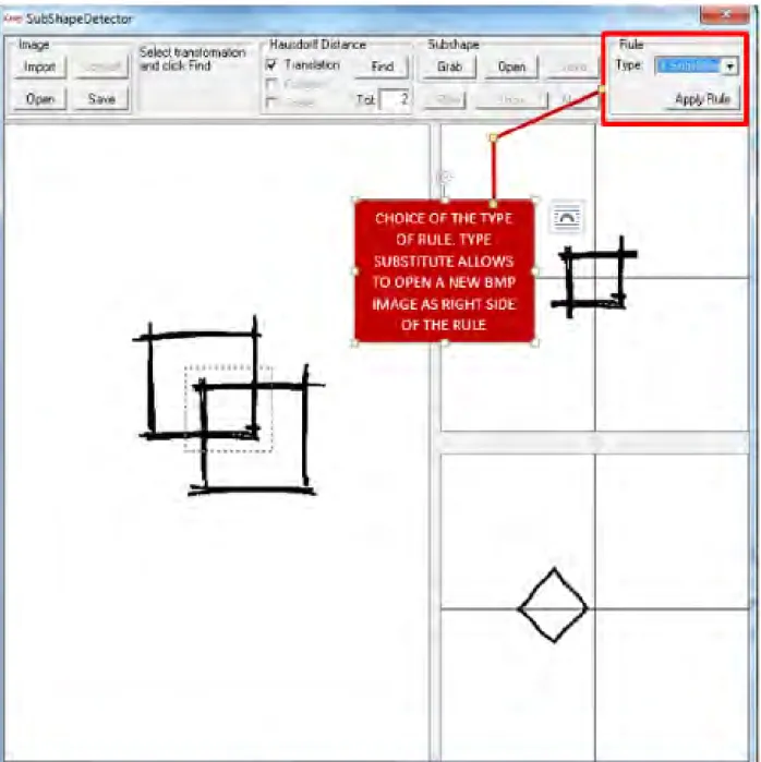
The second option is the command Substitute, which opens a new image file that is used as the right side of the rule (Fig. 12).
Figure 12. Bitmap file for definition of the right side of the rule (from: Subshape)
Task 3 – SG application:
To apply the SG rule, after defining the left and right shapes of the substitution rule, we must use the Find button, which makes the match. If more than one match can be found, we can navigate between them to select the desired one. As seen in the image bellow, the menu name is not clear for this function (Fig. 13).
Figure 13. Matching of the rule (from: Subshape)
After selecting the desired match we must use Apply Rule. We do not have a single menu to make the match and apply the rule. One must jump from one side to the other of the interface (Fig. 14).
Figure 14. Substitution Rule application (from: Subshape)
Task 4 - Solutions manipulation and 5 - SG modification After this process, there is no possibility of handling the obtained drawing. To change the created SG we must repeat the process from the beginning.
The menus are not organized according to the sequence of actions to be taken, or set of actions related to the same task. This CW was only possible following the user's guide, as it was not understandable how to perform the correct order of the commands without reading the manual instructions. Also, if they are not performed in the correct sequence, the application crashes.
2.5.3. SGI [12]
SGI is an interpreter for two dimensional SG that supports
real-time subshape detection and the author defined its Graphical user interface with the purpose of having an easy and visual manipulation of the shapes and rules.
Task 1 - Shape creation
This application displays multiple windows with information on the shapes, rules and grammars. The logic of creation of all elements is simple and straightforward, the presentation of information is graphical and direct.
The creation of the shapes is performed using freehand lines and curves. We can create multiple shapes, name them and organize them. The left panel is used to organize and create new shapes and the lower panel is used to check and classify the shapes created (Fig. 15).
Figure 15. Shape creation and name configuration (from: SGI)
It is possible to create multiple shapes and use them for the rule creation (Fig. 16).
Figure 16. Shape definition - more than one allowed (from: SGI)
Task 2 - Rule creation
The creation of rules is very simple and it is shown graphically. In the Rule tab we can select rules of Substitution, Modification and Addition (Fig. 17).
Figure 17. Rule type selection (from: SGI)
After selecting the rule type, the shapes for the left and right side of the rule are chosen from the shapes created previously. The rule is graphically displayed (Fig. 18).
Figure 18. Choice of shapes for the left and right side of the rule (from: SGI)
The positioning of the drawn shapes is not taken into account, but the leftmost window can be used to manipulate the shapes, both in position and in size. It is automatically viewed the changes of the rule (Fig. 19).
Figure 19. Direct manipulation of the objects for rule creation (from: SGI)
Task 3 – SG rule application
The SG application is made in the window Render with the choice of the number of iterations (Fig. 20).
Figure 20. SG rule application through selection of iterations number (from: SGI)
Task 4 - Solutions manipulation and 5 - SG modification
The manipulation of solutions is possible only in the change of the number of iterations of the rules created. If we want to change the left or the right side of the rule, we must create a new rule.
2.5.4. SGDE [13]
SGDE was created by the authors with the purpose of implementing a system that allowed the user to edit and testing SG, switching easily between the two types of activity, emphaticizing this with the graphic manipulation of the shapes.
Task 1 – Shape creation
The CW to this application was only possible using the manual, since there are menus that are not easily seen (they are show as usually are shown the names of the windows, looking invisible). It has also become impossible to explore the application without use of manual because of inaccurate tracking of the necessary steps leads to malfunctioning of the software. The application allows creating shapes by drawing rectangles and lines in a limited drawing area. The procedure is the same as the one for the creation of initial shapes and general shapes for the left and right of the rule (Fig. 21).
Figure 21. Creation of polygonal shapes (from: SGDE)
Task 2– Rule creation
Creating rules is accomplished through the design of the left and right side shapes, after a new rule creation command in the Rule menu (Fig. 22).
Task 3 – SG application
The application of a rule is performed on the Run menu, or using the buttons at the right. All possible outcomes are shown in a new window. There are buttons to manipulate the display of the initial shape (from top, side views or backwards), but as the shapes are only bi dimensional, this option does not give great advantages (Fig. 23).
Figure 23. Solutions visualization (from: SGDE)
Task 4 - Solutions manipulation and 5 - SG modification
There is no possibility of manipulating the obtained solutions. We can edit the initial shape and left and right shapes of the rule, creating a new SG rule.
2.5.5. SD2 [14]
SD2 comes as an evolution of the Subshape, done by the same authors. In this newer implementation, the user can freely draw shapes, instead of just importing them.
Task 1 – Shape creation:
In this application we can freely draw shapes. The design is performed using only free lines, which hinders the creation of geometric shapes, but allows great artistic freedom (Fig. 24).
Figure 24. Free shape drawing (from: SD2)
Task 2 – Rule creation:
The creation of rules is performed by adding drawings to the left and right side of the rule (drawn directly or by opening saved images). In the bottom pane are collected the opened or designed shapes, while in the right pane the rules are created (Fig. 25).
Figure 25. Shape selection and rule definition (from: SD2)
Task 3 – SG application:
The application of the SG is performed by selecting the initial shape, the rule to apply and using of the “D” button (design) where you can search for the rule match and apply the rule. All the rules are replacement ones (Fig. 26).
Figure 26. Match of the rule and SG application (from: SD2)
Figure 27. Solids creation (from: Spapper)
Task 4 - Solutions manipulation and 5 - SG modification
There is no the possibility of manipulating the solutions, changing what the SG created. Only the creation of new rules and solutions is allowed.
2.5.6. Spapper [15]
This application is the most sophisticated of the group, in the sense that it is a plug-in for use in CAD applications. It allows the creation of three dimensional shape grammars, with no restriction on the orientation of the objects. Task 1 – Shape creation:
As this implementation is a plug-in for use in CAD applications, we followed the user guide and used the free software. To accomplish the tasks the manual was essential, despite the software's resemblance with other CAD applications. FreeCAD allows the creation of three-dimensional solids, and the tools of this application are used to create shapes (Fig. 27). Task 2 – Rule creation:
The Spapper plug-in allows the drawing of shapes in the left and right side of the rule, using the FreeCAD commands to create three-dimensional solids. The rules created use FreeCAD objects visualization and the handling is made with the modification of the size parameters of the solids. However, there are a back and forward steps that do not make the use of the tool very logic or user-friendly. We need to load the plug-in to open the windows that allow the creation of the left and right shapes, but this action makes the drawing tools disappear. Thus, we need to reload the drawing tools, which make the plug-in disappear and, after drawing the shapes needed, re-load the plug-in to be able to create the rules and SG. This means we cannot have open all the tools needed during the entire process (Fig. 28).
Figure 28. Left and right side of rules creation (from: Spapper)
Task 3 – SG application:
After creating the rule for the left and right solids, we can apply the rule with the corresponding command. The buttons are not obvious; as it was only possible to understand their function using the manual. It was also only possible to apply the rule saving it, closing the application and re-uploading the saved rule.
The SG application window allows choosing the number of iterations and the number of desired solutions. It also allows rule visualization (Fig. 29).
Figure 29. Shape application (from: Spapper)
Task 4 - Solutions manipulation
This is the only application that provides full handling of the solutions. It is possible to manipulate the solids obtained with total freedom. This is very interesting for the use of SG as a creative partner and in the design / architecture project. Task 5 - SG modification
As in most applications, we cannot directly change the rules created. New rules have to be made with the desired data from scratch.
After completing the CW through these six SG implementations, it is important to stress that all of them seem to be in an early stage of development or just for simple manipulation/visualization of SG. They all seem to be fit for educational purposes, rather than to professional architectural or design projects.
3. Results
The present analysis has been carried out in accordance to the purposes of the CW, that is, with the ease of learning and the manipulation of the computer application in sight. However, although out of the scope of this analysis’ goals, it is interesting to point out a few understandings. It is very important to state that most of the applications are rather generic and simplified, not only concerning the interface but also in its functioning.
According to the objectives set for this study, one can easily assume that none of the tested applications would be easily adopted for an effective use in design and architecture creative projects. The lack of correspondence between these applications and the ones that are generally used by these
groups of users can be pointed as a great obstacle to its adoption, as shown below.
Since these users are characteristically used to CAD tools, which have highly qualified interfaces, the non-resemblance with these tools is one relevant aspect to point out. This limitation can be found not only at the interface level, but also in the way the tasks are performed. Though working with SG can be rather specific, there is no resemblance, for example, in the way the shapes are drawn in the tested applications, neither there is one in the generic manipulation of the applications, when the handling of the computer-assisted drawing is generally established.
Specifically, the integration of Snapper [15] with a CAD application is a good solution to address this issue. Considering the SG applications as a plug-in for the CAD tools may be an option, even though it is not reasonable to consider it in our approach to the IM-sgi, as the use of SG is much broader.
The Shaper 2D [10] is an application that stands out because it offers a very easy handling and is very intuitive, making direct object manipulation a reality. The fact that it is very easy to use is a great help.
From the comparison table, we can see that SGDE [13] has the general characteristics one would wish on a SG computational application. But, as all the other implementations, there is the need to make the interface more appealing, more user-friendly and suitable to the designers’ needs.
This Cognitive Walkthrough is a very important step in our research, as it allows us to conclude that we cannot find any resemblance or followed guidelines in the existing SG applications. As we can find a considerable range of SG computational applications, we could understand patterns in
the way the authors address the tasks and the interface, but that is not true.
There are common general issues that can be pointed after our CG and that should guide our definition of an interface model for SG implementations. There are four main important conclusions:
1 – No resemblance with the common used computer applications in the architectural and design fields. This creates an immediate barrier to the use of these applications for design purposes, as designers would have to learn new ways to manipulate the applications;
2 – The interfaces are simple and outdated, lacking in being appealing to the users we want to address, that are sensible to visual style;
3 – Lack of organization between windows, menus and buttons, many times making the user navigate through different areas of the screen for a simple task;
4 – None of the applications show an interface that guides the user through the sequence of tasks he should do to be successful in creating and using SG.
With the CG performed, we have a starting point of important issues that IM-sgi should answer. As defining the interface is a very big time consuming task, we believe that with IM-sgi we address the issues that are usually left behind when developers create the SG implementations and help these implementations take a leap forward, leaving the investigational field to enter the design practice field.
4. Conclusions
This work aims to help SG implementations to effectively enter in the design practice and become a relevant way of exploring ideas and design solutions.
The use of computer applications in the fields of design and architecture has suffered changes through time. Starting with the computer performing the handwork of the designer, the evolution has gone in the direction of becoming a collaborator in the design process [19]. According to Akin, the fact that computers serve mostly as a sophisticated design tool can be linked, not only to the lack of technological development, but also to the fact that it is intimidating for creative designers to use computer applications in their daily work. The author believes that the main problem lies in the fact that systems are developed to perform what the designer, slower or less accurate, is able to accomplish without using the computer. What occurs is that the CAD computing applications tend to not consider the human interface aspects, and moreover the trends of cognitive capacities of the designers.
The best way for the designer of interfaces to think about the new user is to as an expert in its non-computational domain. This view is positive so that the tools support the user's activities like the work in the “real world” [20]. For experienced users, the main issue in using a new computer application is in the relation of the learning time versus the benefits it brings. The important thing is the perception of
gains in productivity or efficiency in time, taking into account the efforts to be familiar with the tool. If these gains are not met or understood, preference is given to the known methods, even if inefficient.
Having in mind the paradigm of the use of SG in the design process, we want to propose a model to address the interface issues related to the use of SG by architects, designer, artist and students, as they all interact differently and with different purposes.
In this text we present our analysis of existing SG computational implementations that we could access and test. In the Methodology chapter we show how we followed an organized Cognitive Walkthrough, from which we describe then the Results and point our Conclusions. This work was done as a preliminary analysis needed for the definition of the desired interface model.
According to the three phases described for the definition of the IM-sgi, further work is to develop the Phases two and three, defining rigorously the IM-sgi model and a graphic interface prototype according to the IM-sgi model that can adapt to different categories of use, user needs and objectives. This prototype is to be tested through interviews to different categories of users (designers/students/experts in SG) for validation of suitability.
REFERENCES
[1] S. Chase, A model for user interaction in grammar-based design systems, vol. Automation in Construction 11, Elsevier, 2002, pp. 161-172.
[2] J. Tching, J. Reis and A. Paio, Shape Grammars for Creative Decisions, 2013.
[3] B. MyerS, A Quick Overview of Human-Computer Interaction, 2008.
[4] F. Karray, M. Alemzadeh, J. Saleh and M. Arab, Human-Computer Interaction: Overview on State of the Art, 2008.
[5] Y. Rogers, S. Helen and J. Preece, Interaction Design - Beyond Human-Computer Interaction, 3rd Edition, 2011.
[6] D. G. Novick , T. Hollingsed and L. Martin , Usability inspection methods after 15 years of research and practice after 15 Years of Research and Practice, Texas: University of Texas at el Paso, 2007.
[7] R. Jeffries, J. R. Miller, C. Wharton and K. M. Uyeda, User Interface Evaluation in the Real World: A Comparison of Four Techniques, New Orleans: Hewlett-Packard Company, 1991.
[8] P. Polson, C. Lewis, J. Riemen and C. Wharton, Cognitive Walkthroughs: A Method for Theory-Based Evaluation of User Interfaces, Colorado: University of Colorado Boulder, 1991.
[9] T. Mahatody, M. Sagar and C. Kolski, State of the Art on the Cognitive Walkthrough Method, Its Variants and Evolutions,
vol. 26, International Journal of Human-Computer Interaction, 2010, pp. 741-785.
[10] M. C. Mcgill, A Visual Approach for Exploring Computational Design, 2001.
[11] I. Jowers, D. HogG, A. Mckay, H. H. Chau and A. d. Pennington, Shape detection with vision: implementing shape grammars in conceptual design, T. U. o. Strathclyde, Ed., Annecy, France: Eurographics Workshop on Sketched-Bases Interfaces and Modeling, 2008, pp. 11-13.
[12] T. Trescak, I. Rodriguez and M. Esteva, General Shape Grammar Interpreter for Intelligent Designs Generations, Tianjin: IEEE, 2009, pp. 235-240.
[13] A. I.-K. Li, H. H. Chau, C. Liang and Y. Wang, A Prototype System for Developing Two and Three Dimensional Shape Grammars, Design Computing @ Cognition Workshop, 2009.
[14] I. Jowers, D. Hogg, A. Mckay, H. H. Chau and A. d. Pennington, Shape detection with vision: implementing shape
grammars in conceptual design, London: Res Eng Design, 2010.
[15] F. R. Hoisl, Visual, Interactive 3D Spatial Grammars in CAD for Computational Design Synthesis, Munique, 2012. [16] C. Wharton, J. Rieman, C. Lewis and P. Polson, The Cognitive
Walkthrough Method: A Practitioner's Guide, Colorado: Istitute of Cognitive Science, University of Colorado, 1993. [17] ISO 9241-210, "ISO Standards," Usability Partners -
Stockholm, 2010. [Online]. Available: http://www.usabilityp artners.se/about-usability/iso-standards. [Accessed 11 2014]. [18] A. Mckay, K. Shea, S. Chase, A. LI, T. Trescak, F. Hoisl, I.
Jowers, C. Ertelt and R. Corriera, Shape Grammar Implementation: From Theory to useable software, Stuttgart: Design Computing and Congnition Workshop, 2010. [19] Ö. Akin, What's Wrong With CAAD? Pittsburgh, 1993. [20] J. M. Carroll, HCI Models, Theories and Frameworks, San
![Figure 1. Control scenarios for the development of Shape Grammar implementations [1]](https://thumb-eu.123doks.com/thumbv2/123dok_br/18218293.877235/3.892.109.805.113.551/figure-control-scenarios-development-shape-grammar-implementations.webp)