julho de 2015
Escola de Engenharia
Manuel José Leal Zamith de Passos
UMinho|20
15
Manuel José Leal Zamith de P
assos
A Radiofrequency Identification System
for the 60 GHz ISM Band
A Radiofrequency Identification Sys tem for the 60 GHz ISM Band
Universidade do Minho
Escola de Engenharia
Manuel José Leal Zamith de Passos
A Radiofrequency Identification System
for the 60 GHz ISM Band
Dissertação de Mestrado
Mestrado Integrado em Engenharia Biomédica
Ramo de Eletrónica Médica
Trabalho efetuado sob a orientação do
DECLARAÇÃO
Nome: Manuel José Leal Zamith de Passos
Endereço eletrónico: [email protected] Telefone: +351 912096755 Cartão do Cidadão: 14170502
Título da dissertação: A Radiofrequency Identification System for the 60 GHz ISM Band
Orientador: Professor Doutor Paulo Mateus Mendes
Ano de conclusão: 2015
Mestrado Integrado em Engenharia Biomédica Ramo de Eletrónica Médica
É AUTORIZADA A REPRODUÇÃO INTEGRAL DESTA DISSERTAÇÃO APENAS PARA EFEITOS DE INVESTIGAÇÃO, MEDIANTE DECLARAÇÃO ESCRITA DO INTERESSADO, QUE A TAL SE COMPROMETE.
Universidade do Minho, _____/_____/_________
A
GRADECIMENTOS
Esta dissertação simboliza o concluir de uma etapa de cinco anos. Cinco anos na cidade de Braga que me transformaram como estudante e me enriqueceram como pessoa. Englobar numa ou duas páginas as pessoas que contribuíram para o meu crescimento é sem margem para dúvida uma tarefa pesada, destinada a fracasso. Espero, ainda assim, que estas me continuem a acompanhar nas futuras etapas que se avizinham.
Quero agradecer, em primeiro lugar, ao Professor Doutor Paulo Mendes, orientador deste trabalho, pelo desafio que me lançou, pela disponibilidade a todas as horas, pela experiência e pela compreensão nas vezes em que nem tudo corria como esperado. Obrigado também pela integração no projeto PTDC/EEI-TEL/2881/2012, patrocinado pela Fundação para a Ciência e Tecnologia, Programa Operacional Temático Fatores de Competitividade (COMPETE) e Fundo Comunitário Europeu FEDER.
Um grande agradecimento aos meus colegas de laboratório de Gualtar, pela boa disposição, pelo ambiente de entreajuda constante e pelo alento que me deram num ano que não foi fácil. Quero destacar o Adriano e o Hugo, companheiros desde o primeiro ano. Obrigado pela amizade, pela empatia e pelas batalhas diárias que me ajudaram a ultrapassar.
A todos os que entraram comigo nesta viagem em 2010, é impossível enumerar os motivos da minha eterna gratidão. Amizade incondicional foi sempre uma característica que vi neste grupo e em mais nenhum. Tenho a certeza que nunca vos vou perder como amigos e que todas as aventuras vão perdurar na nossa memória. Macedo e França, não posso deixar de vos evidenciar porque é a vós que recorro sempre, para o bem e para o mal.
À restante família de Biomédica só tenho a agradecer tudo o que fazem para tornar este curso único. Aos meus eternos “engenheiros”, obrigado por me ensinarem a ser estudante. Aos meus caloiros, obrigado pela gritaria e pela dedicação. Destes últimos, agradeço a três em especial: Bia, Américo e Rei, obrigado por me ensinarem que as pequenas coisas às vezes são as maiores.
Bia e Pi, amigos da cidade berço, estou-vos grato por me fazerem perceber que as amizades, quando são verdadeiras, resistem ao teste do tempo. Foram inúmeros os desabafos que vos fiz. Vocês permitiram-me sempre escapar em alturas difíceis, e festejar em épocas de entusiasmo.
Ao meu irmão agradeço o exemplo que sempre me forneceu. Obrigado por me pores debaixo do teu braço quando precisei, por constantemente me explicares coisas que não
entendo, pelas intermináveis discussões que só me enriquecem. Espero continuar a discordar de ti por muitos mais anos. Nunca mudes, porque como tu não há igual.
Ao meu pai pela força de vontade e de decisão. Obrigado por me mostrares que na perseverança há uma grande virtude. Obrigado por seres assertivo quando me notas inseguro e por me dares tudo o que preciso, sem eu nunca te pedir.
Sobre a minha mãe podia escrever parágrafos intermináveis. Obrigado pelo amor, pelo carinho e por eliminares as minhas fraquezas. Obrigado por me obrigares a perspetivar e por me colocares no caminho certo quando, insistentemente, me desvio. Este ano teria sido muito mais difícil, não fosses tu. Tudo o que serei nesta vida a ti se deverá.
À minha restante família, avós, tios e primos agradeço a preocupação, o interesse e o ambiente inigualável a que me habituaram.
Por último, mas não menos importante, à Rita, que foi um pilar nos meses mais complicados do meu percurso académico. Trazes-me novo alento e obrigas-me a sair dos meus pensamentos, que são o meu pior inimigo. Obrigado por me salvares e por não desistires de mim. Se concluí esta dissertação, a ti o devo.
R
ESUMO
Foi notável, no decorrer da passada década, o crescente interesse em sistemas sem fios de banda larga que comunicam usando ondas milimétricas. Este esforço continuado tem sido motivado pelas oportunidades que se preveem para as tecnologias nesta banda de frequências relativamente ao mercado da eletrónica de consumo.
Esta banda de frequências pode alterar a maneira como tiramos partido das comunicações sem fios em casa devido às suas características peculiares. Os 60 GHz estão posicionados num pico de absorção do oxigénio, o que significa que existe uma alta atenuação atmosférica. Esta qualidade permite uma elevada “reutilização” de frequência, assim como uma segurança acrescentada, como consequência da dificuldade de escuta entre canais. Além disso, a operação em frequências tão elevadas permite o desenvolvimento de agregados de antenas ultrapequenos e dispositivos com níveis de integração sem precedência, para uso em aplicações que exigem equipamentos miniaturizados.
Nesta dissertação, utiliza-se a tecnologia de ondas milimétricas a fim de implementar um sistema de identificação por radiofrequência (RFID) e mostra-se de que maneira pode ser usado para a deteção de instrumentos e esponjas retidas no decorrer de cirurgias.
Corpos retidos depois de uma intervenção cirúrgica são considerados erros evitáveis. Contudo, a documentação existente mostra que continuam a ser uma ocorrência em hospitais de todo o mundo, uma vez que as medidas de prevenção atuais dependem do desempenho humano.
Abordagens baseadas em tecnologia, nomeadamente por identificação por radiofrequência são a solução lógica para o problema. Colocando um pequeno rótulo (tag) no instrumento cirúrgico, este poderia ser identificado por um dispositivo de leitura numa estação base.
Fez-se um estudo da influência das esponjas cirúrgicas e do seu conteúdo em água na propagação das ondas de alta frequência, provando-se o potencial dos sistemas de ondas milimétricas para a aplicação em mão.
O estabelecimento de uma conexão nos 60 GHz foi bem sucedido até uma distância de 5 metros usando um conversor de bandas comercial sem o uso de antenas. Além disso, uma estratégia de multiplexing de frequência foi usada para codificar uma sequência binária no sinal. Para mais, montou-se um sistema de downconversion e retificação usando componentes
off-the-shelf e DIP para uma conversão de RF para DC, a fim de reproduzir a sequência transmitida na receção.
O sistema RFID que foi implementado e validado poderá ser alvo de miniaturização, numa tentativa de melhorar as características da solução proposta, especialmente quando se considera as pequenas dimensões da instrumentação cirúrgica num aspeto geral.
A
BSTRACT
Over the past decade, there has been an increasing interest in mm-wave wireless broadband systems and enabling technologies. This consistent effort has been motivated by the foreseen opportunities for V-band (40 to 75 GHz) technology in the market of broad consumer electronics.
This frequency band could change the way we experience wireless communication at home due to some unique features. 60 GHz is placed in an oxygen absorption peak, meaning high attenuation takes effect, adding advantages such as high frequency reuse and improved security due to the difficulty of eavesdropping. Also, and on a more relevant note, mm-wave operation allows for the development of unprecedented ultra-small antenna arrays and integrated transceiver modules for applications where small footprint devices are of utmost importance.
In this dissertation we apply millimetre-wave technology to implement a radiofrequency identification system and show how it can be used for tracking retained surgical instruments and sponges.
Retained foreign bodies after operative interventions are considered a preventable mistake. However, literature shows that they’re still an occurrence in hospitals worldwide because current prevention methods rely on human performance.
Technology-supported approaches, namely by radiofrequency identification (RFID), is a logical solution to the problem. By placing a small tag in the surgical objects, they could be identified by a reader device in a base-station.
Establishment of 60 GHz link was successful up to distances of 5 meters using a commercial V-band converter without the usage of antennas. A frequency multiplexing strategy was used to code a binary sequence into the signal. Also, a downconversion and rectification system was employed using off-the-shelf and DIP components for RF-to-DC conversion, in order to reproduce the transmitted sequence at reception.
A feasibility study was made in relation to the sponge’s influence, according to water content, in wave propagation, proving the undeniable potential of mm-wave technology for the application at hand.
The system that was implemented and validated could possibly be a target for miniaturization, improving the proposed solution, considering the small sizes of surgical instruments in general.
T
ABLE OF
C
ONTENTS
Agradecimentos ... iii
Resumo ... v
Abstract ... vii
List of Figures ... xi
List of Tables ... xiii
List of Abbreviations and Acronyms ... XV Chapter 1 Introduction ... 1
1.1 Retained Surgical Instruments ... 1
1.2 Technology-supported Approaches ... 5
1.3 Motivation ... 7
1.4 Contributions ... 8
1.5 Outline and Structure ... 10
Chapter 2 mm-Waves for Short Range Communication ... 11
2.1 Small-size, Highly Integrated Transmitters and Receivers ... 11
2.2 Available Bandwidth ... 19
2.3 Industrial Standards for the 60 GHz ISM Band ... 19
2.4 Atmospheric Factors ... 20
2.5 Propagation ... 21
2.6 RFID Based on Millimetre Waves ... 24
2.7 Examples of RFID Devices for the 60 GHz ISM Band ... 26
Chapter 3 Automatic Identification Systems ... 29
3.1 Types of Tags ... 30
3.1.1 Active Tags ... 31
3.1.2 Passive Tags ... 31
3.2 Role of the Reader ... 32
3.3 Accessing Multiple Tags Simultaneously ... 33
3.3.1 Conflict-free Access Protocols ... 34
3.3.3 Carrier Sensing Protocols ... 36
3.3.4 Collision Resolution Protocols ... 37
Chapter 4 Implementation of an RFID System Using mm-Waves ... 39
4.1 Communication Protocol ... 40
4.2 Hardware ... 41
4.2.1 Block Diagram of the RFID System ... 42
4.2.2 IF Signal Generation and Modulation ... 44
4.2.3 V-band Converter by Sivers IMA ... 45
4.2.4 Decoding the Intermediate Frequency Signal ... 47
4.2.5 Control Unit of the RFID System ... 50
4.3 Software ... 52
4.3.1 Program for the Microcontrollers ... 52
4.3.2 Configuration of the Converter’s Control Board ... 58
4.4 Suggested Protocol for Implementation in an Operating Room... 59
Chapter 5 RFID System Characterization ... 61
5.1 60 GHz Link between Tag and Reader ... 61
5.2 Downconversion to 5 MHz and Rectification Circuit ... 65
5.3 Microcontroller Communication ... 69
5.4 Case study ... 70
Chapter 6 Conclusions and Future Work ... 75
6.1 Conclusions ... 75
6.2 Future Work ... 77
References ... 79
Appendices ... 89
Appendix A: Assembling the RFID system ... 89
Digital Lab Connections ... 89
V-band Converter boards ... 89
Voltage Controlled Oscillators and Mixers ... 91
Coaxial Amplifiers ... 93
Decoding Circuit in Breadboard ... 93
L
IST OF
F
IGURES
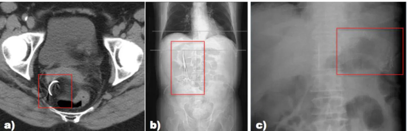
Figure 1 – Different foreign bodied retained during surgery: a) Retained needle detected by a
CT scan to the pelvis; b) Retained clamp detected by an abdominal radiograph; c) Retained
opaque sponge detected by an abdominal radiograph. ... 2
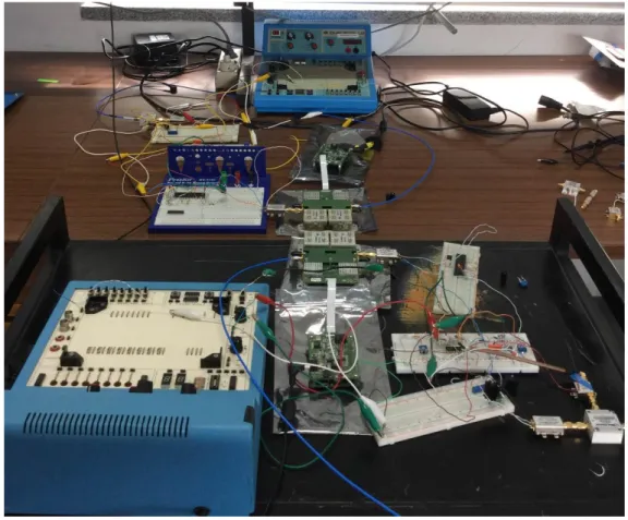
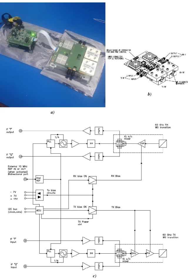
Figure 2 – Photograph the implemented RFID system. ... 8
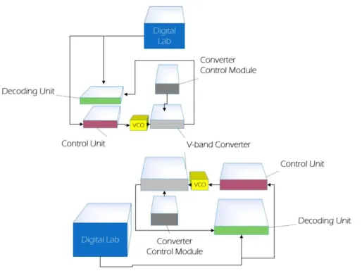
Figure 3 – Block diagram (in perspective) of the implemented RFID system, showing the separate components. ... 9
Figure 4 – Frequency spectrum and available bandwidth. ... 19
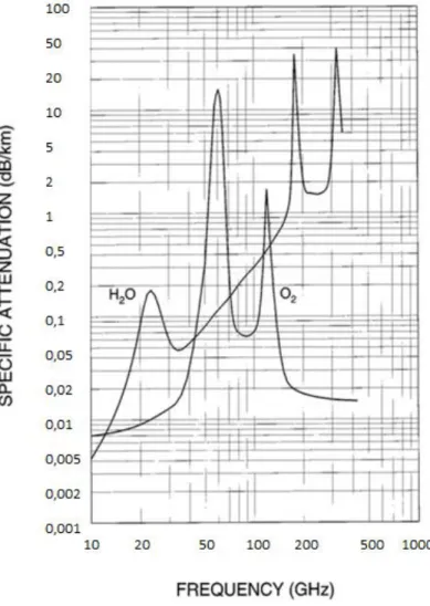
Figure 5 – Specific water vapour and oxygen attenuation values according to frequency. T=20 ºC, p = 1atm, h = 0 Km. ... 21
Figure 6 – Basic components on a simple RFID system. ... 30
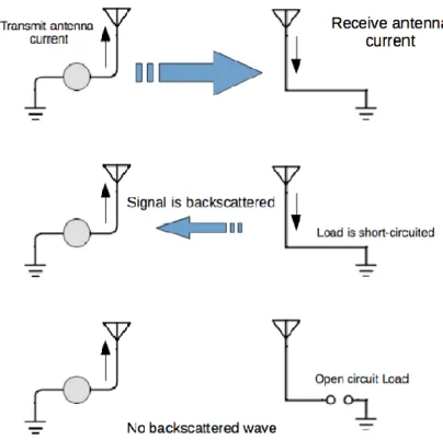
Figure 7 - Simple representation of the backscattering principle. ... 32
Figure 8 – Overview of the system’s components. ... 39
Figure 9 – Communication diagram for a link at the 60 GHz ISM band with the assembled setup. ... 40
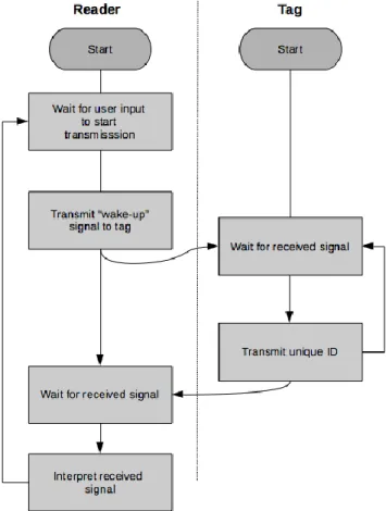
Figure 10 – Diagram of the communication protocol between reader and tag. ... 41
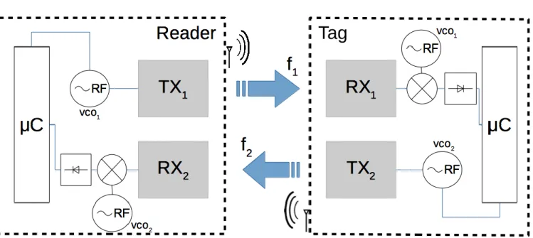
Figure 11 – Diagram showing an overview of the full RFID system. ... 42
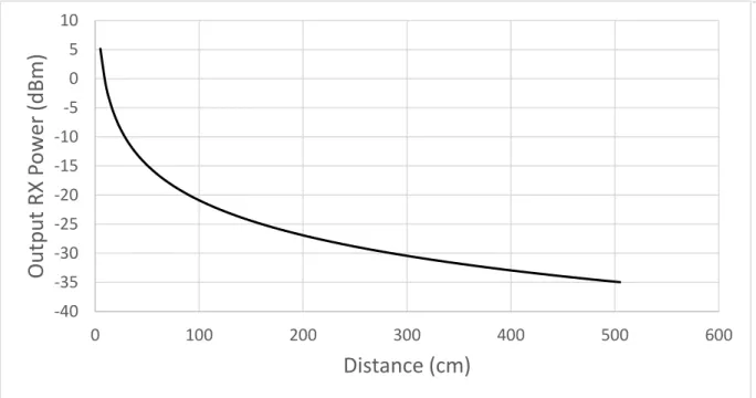
Figure 12 – Output RX power according to distance for a power input of 20 dBm. ... 43
Figure 13 – VCOs used for signal generation. ... 44
Figure 14 – a) Picture of the Sivers IMA FC1005V00 and control board; b) Sketch with pin diagram; c) Block diagram. ... 46
Figure 15 – Basic principle of downconversion. ... 47
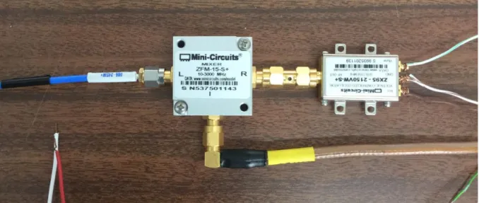
Figure 16 – Photograph of the downconversion unit. ... 48
Figure 17 – Block diagram of the decoding circuit. ... 48
Figure 18 – Implemented DIP decoding circuit. ... 49
Figure 19 – Schematic of the decoding circuit. ... 49
Figure 20 – Connection diagrams of the control unit: a) Reader; b) Tag. ... 51
Figure 21 – Flowchart of the main function of the Microcontroller Unit (Reader). ... 54
Figure 22 – Flowchart of the Interrupt Service Routines of the Microcontroller Unit (Reader): a) Timer Compare Match; b) Pin Change; c) External Interrupt. ... 55
Figure 24 – Flowchart of the Interrupt Service Routines of the Microcontroller Unit (Tag): a)
Timer Compare Match; b) External Interrupt. ... 58
Figure 25 – Example of converter configuration: a) TX module; b) RX module. ... 59
Figure 26 – Assembled setup for a link at the 60 GHz ISM band. ... 61
Figure 27 – Setup used to implement the link at 58 GHz, with different blocks differentiated. ... 62
Figure 28 – Output intermediate frequency RX power according to: a) Increasing distances separating tag and reader; b) Different rotation angles at a fixed distance of 4 m. ... 63
Figure 29 – Comparison between calculated and experimental values for the RX output power according to distance. ... 64
Figure 30 – Setup used to implement the link at 58 GHz at different angles, with different blocks differentiated. ... 65
Figure 31 – Spectral Characterization of the Downconversion block. ... 66
Figure 32 – Characterization of the Rectification block. ... 68
Figure 33 – Connection diagram to test the communication between control units. ... 69
Figure 34 – Communication between reader and tag. Channel 1: output from tag; Channel 2: output from reader. ... 70
Figure 35 – Illustration of the placement of the tags and reader. ... 71
Figure 36 – Laboratory facilities where the measurements were conducted. ... 72
Figure 37 – Materials used: (left) Cotton ball; (right) PVA sponge;. ... 73
Figure 38 – Proposed integration solution: a) Artistic view; b) Three-dimensional view ... 77
Figure 39 – Connections of the control unit. ... 89
Figure 40 – Connection diagram of the converter board. ... 91
L
IST OF
T
ABLES
Table 1 – Most common explanations for falsely correct counts. ... 4
Table 2 – State-of-the-art of small, highly integrated transmitters and receivers. ... 8
Table 3 – Summary of the research presented in section 2.1. ... 17
Table 4 – Attenuation for different solid materials.. ... 24
Table 5 – Transmission frequency bands used on RFID systems. ... 24
Table 6 – Power and Frequency Budget (VCOs). ... 42
Table 7 – Power and Frequency budget (downconversion unit). ... 44
Table 8 – Interrupts of the reader device program. ... 53
Table 9 – Interrupts of the tag device program ... 56
Table 10 – IF output power measurements with tag placed in the ground. ... 73
Table 11 – IF output power measurements with tag placed at reader’s height ... 74
Table 12 – Com-port settings for converter configuration ... 90
Table 13 – Configuration example for the converter boards ... 90
Table 14 – Connection summary of the VCOs... 92
Table 15 – Connection summary of the mixers ... 93
Table 16 – Connection summary of the amplifiers ... 93
Table 17 – Decoding circuit’s connection summary ... 94
L
IST OF
A
BBREVIATIONS AND
A
CRONYMS
ACK Acknowledgement
ACS American College of Surgeons AM Amplitude Modulation
AORN Association of periOperative Registered Nurses ASK Amplitude Shift Keying
Auto-ID Automatic Identification BMI Body Mass Index
BPSK Binary Phase Shift Keying
CMOS Complementary Metal-oxide-semiconductor CRP Collision Resolution Protocol
CSMA Carrier Sensing Multiple Access CT Computed Tomography
DC Direct Current DIP Dual In-line Package
EAS Electronic Article Surveillance FDMA Frequency Division Multiple Access FM Frequency Modulation
GPS Global Positioning Service HEMT High-electron-mobility Transistor HF High Frequency
HJFET Heterojunction Field Effect Transistor HTCC High Temperature Co-fired Ceramic
HW Hardware
IC Integrated Circuit
IEEE Institute of Electrical and Electronics Engineers ISR Interrupt Service Routine
ISM Industrial, Scientific and Medical
JCAHO Joint Commission for the Accreditation of Hospitals LCP Liquid Crystal Polymer
LED Light-emitting Diode LNA Low-noise Amplifier LO Local Oscillator LOS Line-of-sight
LTCC Low Temperature Co-fired Ceramic MCU Microcontroller Unit
mm-wave Millimetre Wave
mHEMT Metamorphic High-electron-mobility Transistor MMIC Monolithic Microwave Integrated Circuit MMID Millimetre Wave Identification
NLOS Non-line-of-sight OOK On-off Keying OR Operating Room PA Power Amplifier PCB Printed Circuit Board
pHEMT Pseudomorphic High-electron-mobility Transistor PLL Phase-locked Loop
QAM Quadrature Amplitude Modulation RF Radiofrequency
RF-DAC Radiofrequency Digital-to-analogue Converter RFDS Radiofrequency Detection System
RFID Radiofrequency Identification RSI Retained Surgical Instruments
RX Reception
SNR Signal-to-noise Ratio
SW Software
TDMA Time Division Multiple Access TX Transmission
UHF Ultra High Frequency
Chapter 1
I
NTRODUCTION
Medical errors can be defined as the failure of a planned action to be completed as intended or the use of a wrong plan to achieve an aim. Preventable medical errors have always been an occurrence in hospitals all around the world [1].
The extreme complexity and diversity of the tasks involved in medical care leads to these mistakes and the fact that they happen infrequently, makes it hard for some institutions to study them further and identify risk patterns [2]. In the present chapter, we take a look at the medical error at hand, which happens when a surgical instrument or sponge is misplaced inside a patient’s body during the course of surgical procedures. Recent literature continues to focus on risk factors, prevention methods, complications and technological trends, making us believe that retained surgical instruments (RSI) are a recurring problem [3]–[5]. Despite the efforts to minimize the occurrence of RSIs, zero incidence remains elusive.
Furthermore, we present automatic detection through a radiofrequency identification system as a mitigation of this problem, as well as what the motivations of this study and the scientific contributions that were made.
1.1 Retained Surgical Instruments
One persistent and poorly understood error is the misplacement of surgical instruments and sponges inside patients’ bodies in the course of surgery. Despite being a rare event, it can lead to serious consequences for the patients and the medical care facility as well. There are reports of retained instruments in different surgical procedures such as prostatectomy, thyroidectomy,
cardiothoracic surgery (eg. sponges in the lung parenchyma, pleural space, and pericardium), neurosurgery (eg. sponges in the neck, spine), and orthopaedic surgery [6].
The incident of a foreign body varies from 1 in 5000 to 1 in 18000 overall, and up to 1 in every 1000 intra-abdominal operations [2], [3], [7]–[9], although no body cavity has been exempt. This roughly translates to one case per year in a hospital that conducts at least 10,000 cases per year [6]. Furthermore, mortality rates that result from unintended retained foreign bodies are as high as 11% to 35% [10]. Figure 1 illustrates three different examples of foreign objects left behind in surgical procedures.
There are documented records of all kinds of retained objects, such as prosthesis, surgical clamps and needles [6] and even an asepto bulb [11]. However, surgical sponges and gauze sum up to about half of the claims for foreign retained bodies (48% to 69%) [12].
The relative rarity of this event does not diminish its physiological and psychological effects on patients and their families [7]. Plenty of complications can take place after a surgery in which a foreign body was retained, such as perforations, sepsis and even death [2], [8].
As an example, a gossypiboma, which is the name given to a retained surgical swab or sponge [13] can present itself in an immediate or a delayed phase. Early symptoms like nausea, vomiting, rectal bleeding and altered bowel habits can indicate an abscess formation or a fistula in the acute phase. Secondary to the exudative inflammatory reaction, the patient can also present fever, anorexia and weight loss. In this phase, it’s not abnormal to detect penetration through the wall of a neighbouring organ, with migration into the organ. This results in obstruction or gastrointestinal haemorrhage from erosion of blood vessels [13].
The discovery of the misplaced items inside the patients’ bodies most commonly happens through a postoperative x-ray [12]. However, ultrasound, magnetic resonance imaging and
Figure 1 – Different foreign bodies retained during surgery: a) Retained needle detected by a CT scan to the
pelvis; b) Retained clamp detected by an abdominal radiograph; c) Retained opaque sponge detected by an abdominal radiograph. Adapted from [6].
Introduction computed tomography (CT) have also been used for diagnosis and the last mentioned has proven to be the most reliable method for detection of retained surgical instruments.
As so, the need for a follow-up surgery to remove the foreign body and drain the associated infectious collection is frequent [12] and the disclosure of an RSI to the patient is mandatory by law [4]. Moreover, the risk that disclosing a medical error (especially a preventable one) to a patient, cannot be disregarded, as it could prompt a lawsuit [14].
As can be immediately concluded, these situations can present serious complications, not only to the patients involved, but also to the medical facilities and professionals. In the case of a medical liability claim, defending the surgical team can be difficult and expensive [7], [12], [15]. In a study demonstrating the prevalence of 40 cases in a 7-year period, an expenditure of about $500,000 for defence costs and $2,000,000 for indemnity payments indicates the significance of the problem [12].
In addition, avoidable mistakes made in an operating room (OR) can attract wide critical press coverage [2] and represent significant organizational and personal embarrassments [7] . Yet, these errors persist.
Procedures to try to prevent these events are in effect in ORs all across the world. Guidelines have been promulgated by the American College of Surgeons (ACS), the Association of periOperative Registered Nurses (AORN), and oversight and regulatory agencies such as the Joint Commission for the Accreditation of Hospitals (JCAHO) [2], [6]. Nevertheless, it’s up to every individual facility to develop their policy as an attempt to improve the provided service. In most hospitals, current prevention measures include a surgical count performed by members of the surgical team [2], [6], [10], [13]. These counts are normally performed by registered nurses and technicians and, according to the most recent guidelines published by the AORN, counting should be done:
Before the procedure, to establish a baseline and identify manufacturing faults; When new items are added to the field;
Before closure of a cavity within a cavity (eg. uterus); At skin closure;
At the time of permanent relief of the person responsible for counting [16].
Despite this, however, errors keep occurring. Counting is heavily dependent on human performance and is subject to inherent error. There are three separate circumstances where reliance on counting can mislead: either no count is performed, or there is miscount (cases where the count is incorrect) or falsely correct counts [6], [13]. The last one is the most common
occurrence of the three and makes the surgical count an unsafe practice. In fact, a study in [9] found that 66% of RSIs occurred when the count was claimed as correct and in [17] it’s demonstrated that the sensitivity of surgical counts adds up to about 77%.
Adding to this, existing protocols have been criticized for interfering with the surgical flow [7]. Table 1, collected from [12], shows the diversity of explanations given by medical professionals when confronted on why these errors occur. In addition, in a study from 2013 [3], it is stated that the three main obstacles to reducing the incidence of RSIs are identifying lost items, reducing the rate of falsely correct counts and improving team attentiveness and compliance with recommended procedures.
We can safely conclude that these problems are unsolvable, as human mistake is always an important variable. Technology-supported approaches should be considered.
Table 1 – Most common explanations for falsely correct counts.
Explanations given for incorrect counts
Team fatigue End of shift Adherent sponges
System problem
Surgeon declined repeat count Falsely negative intraoperative x-ray
Excessively bloody procedure Incorrect package count
Conversation in the OR Registered nurse left the OR
No count performed Sponge looked for, not found
Nonetheless, other risk factors associated with RSIs include emergency surgery, high body mass index (BMI), unexpected changes in procedures and long duration of surgery [15].
Other recommendations state that only radiography-detectable sponges are to be used and that they should be counted once at the beginning and twice at the end of every open-cavity procedure. If a count is incorrect, that is, if all materials are not accounted for, manual or radiography oriented exploration is to be performed [2], [16].
Introduction that an RSI does not occur, especially for sponges and needles. In [9], only 67% of the objects left in patients during surgery were identified by an intraoperative X-ray and in [12] 10,3% of retained sponges were falsely reported as negative in radiography results. As so, not only do intraoperative imaging techniques provide suboptimal information, they’re also time consuming, expensive, and expose patients to unnecessary radiation. The cost of performing routine intraoperative radiographies to prevent retained instruments is estimated to be 11,5 million dollars for every harmful detected object [15].
1.2 Technology-supported Approaches
The need for an automatic solution to this problem is imminent, as it would substantially reduce the unavoidable human mistake from this equation. In 2005, electronic article surveillance (EAS) applied to surgical sponges was introduced in [18]. This technology is commonly used in commercial applications to prevent theft in stores. This system proved an initial assessment of using electronic detection systems to possibly prevent retention of sponges.
An electronic system in which barcodes are applied to the swabs is already an FDA-approved solution. These represent two-dimensional data matrixes that grant each sponge a unique identifier. A scanner can be located in close proximity to the back table so that sponges can be counted as they are passed off the table, in a “grocery store” checkout fashion. Every instrument must be passed through the device in the beginning and end of the procedure [19]. This barcode solution is already available in the market and improves the reliability of surgical counting, as proved in a randomized trial from 2008 [20]. In this study, 300 general surgery operations were performed comparing a traditional counting system to a bar-coded sponge system. Outcome was improved, as about twice of the RSIs were detected and medical professionals seemed open to adopting the system. However, human mistake is still a problem in this methodology implies a learning curve, demanding training for all the surgical professionals. Also, surgery time was noted to require 12 minutes more on average (average surgery duration of 2,90 hours).
As another alternative, the use of radiofrequency detection systems (RFDS) holds great promise in this issue and there is application in the market already, by RF Surgical Systems, Inc. [21]. That system uses a passive RF tag embedded in sponges that can be detected if a wand is within 24 inches of it. This wand is connected to a detection console that generates an audible
and visible alarm when the tag is detected.
In 2011 [22] and 2013 [23] complete cross-over studies were performed that proved this method’s level of accuracy surpasses any other and should be seriously considered when redesigning health care systems in order to enhance patient safety. Nevertheless, implementation of this system also requires training for the staff and is viewed as complementary to manual counting. Also, each tag contains no specific information about the surgical instrument where it’s placed, so the system cannot distinguish between instruments; rather, it can only identify whether the tag is within reach, inside the patient or in any other place in the OR. In addition, the system cannot count tags, as the signal will have the same intensity whether there are 1 or 5 sponges to be detected.
An RFID system should be able to both count and detect, gathering the advantages of bar-coding and RFDS. This technology is faced as the most promising, given its unobtrusiveness and easy integration in healthcare systems. RFID does not require focused passing through scanners (unlike bar-coded methodologies) and it enables faster and simultaneous scanning of multiple items, minimizing human intervention in task performance [24].
ClearCount Medical [25] developed an RFID system that embeds a unique identification chip into each surgical sponge. There is a separate computer console with a scanning bucket into which used sponges are introduced.
Unopened packages of sponges are placed on a front panel to be electronically counted. Then the sponges are opened and placed on the sterile field. As used sponges are retrieved, the scanning bucket will count them individually. If there is a miscount, a wand that is attached to the bucket by a cord is used for inspection.
The passive chip is about 10 mm2, which makes it noticeable and too large to fit through minimally invasive surgery trocars [26]. Also, the need to use a large wand attached to a main device by a cord can disrupt surgical flow, as well as be time consuming.
A clinical evaluation was made in 2006 [27] to prove the feasibility of ClearCount Medical’s system, and it showed promising results. However, this early study lacked power to detect sensitivity and specificity and did not account for variability in the patients (such as weight and BMI), so there is still limited information about the accuracy and effectiveness of this technology [15].
One relevant concern in relation to the use of technology-supported approaches as part of surgical protocol is the financial investment. A recent report (2014) [15] featuring a cost-benefit analysis of radiofrequency technology showed that, in fact, the use of RF devices could represent a high initial cost because of the price of detectable sponges and wands. However,
Introduction one should account for the costs saved and avoided.
Decreased use of radiography equipment could save the hospital a lot of money, because of technician and radiologist fees. Also, avoided costs concerning readmission of patients, unnecessary follow-up surgical procedures and legal costs are a consequence of using more efficient equipment. The study concluded that hospitals could potentially save thousands of dollars annually.
However, no detection system has been assessed as a replacement for manual counting protocols and procedures, as current official recommended preventive measures don’t yet include technology-supported approaches.
1.3 Motivation
“Never events” like RSIs are considered to be “avoidable”, however, current measures to prevent them consist of protocols and recommendations, which are also dependable on human performance. It’s obvious that an automatic solution based on technology would be a step towards erasing human error from the equation and saving patients from complications resulting from these mistakes.
Millimetre waves represent frequencies between 30 and 300 GHz and are a trend in the electronics engineering and investigation world; as they could be an answer to the bandwidth shortage of wireless systems, as well as provide very large data rate links. However, for this dissertation, we’re interested in other differentiating characteristics that make this band unique, such as allowing high-frequency reuse and the miniaturization of antennas to extremely small sizes.
Recent developments in mm-wave technology prove communications in the 60 GHz band could be the solution for the development of miniaturized devices for indoor communications.
Table 2 shows examples present in the most recent literature. These examples show how very
small-sized devices with low power consumption for the 60 GHz band are a reality already. A more complete study is presented in section 2.1.
Since millimetre wave technology can be advantageous and present itself as a feasible solution to the RSI problem, the aim of this dissertation is to develop an RFID system working in the 60 GHz ISM band, which can be used to automatically identify objects inside of a room such as an operating room.
Table 2 – State-of-the-art of small, highly integrated transmitters and receivers.
Reference Year Technology RX/TX POUT (dBm) PC (mW) Size (mm2)
[28] 2012 40 nm CMOS Single TX and
RX IC 10,2
TX: 1820
RX: 1250 0,7
[29] 2014 65 nm CMOS Single TX and
RX IC N/A
TX: 251
RX: 220 4,2
[30] 2014 40 nm CMOS TX 10 75 2,38
POUT – Output power of device.
PC – Power consumption of device.
1.4 Contributions
All components of an RFID system using mm-wave communication were implemented and feasibility of such system to mitigate RSI was proved. Figure 2 shows the implemented full system and Figure 3 illustrates a block diagram for better comprehension of the different components.
Introduction
The tag and reader devices consist of V-band converters by Sivers IMA that allow a link in the 60 GHz band to be made. Downconversion and decoding circuits were implemented using DIP and off-the-shelf components.
For intermediate frequency signal generation, VCOs were used, whose tune voltage was controlled by a microcontroller, allowing for a frequency multiplexing modulation strategy.
In addition, a case study is presented in order to study the influence of the most commonly used materials for surgical sponges, as well as the effect of water content in the power attenuation of the signal.
This dissertation also contributes with a general analysis of the developments made concerning highly integrated transceiver technology for the 60 GHz ISM band between 1997 and 2014.
Additionally, this study has also contributed to the following publications:
H. Dinis, M. Zamith, J. Fernandes, J. Magalhães, and P. M. Mendes, “On-Chip, Efficient and Small Antenna Array for Millimetre-Wave Applications,” in International Workshop on Antenna Technology (iWAT2015), 2015;
Zamith and P. M. Mendes, “Towards an RFID microsystem for surgical instrument detection using millimetre waves,” in 2015 IEEE 4th Portuguese Meeting on Bioengineering (ENBENG), 2015, pp. 1–5;
M. Zamith, J. Magalhães, P. Anacleto, and P. M. Mendes, “60 GHz On-Chip Antenna Array with Efficiency Improvement Using 3D Microfabrication Technology,” in 9th European Conference on Antennas and Propagation (EuCAP2015), 2015;
H. Dinis, M. Zamith, P. M. Mendes, “Performance Assessment of an RFID System for Automatic Surgical Sponge Detection in a Surgery Room,” in 37th Annual International Conference of the IEEE Engineering in Medicine and Biology Society (EMBC), 2015. Accepted;
H. Dinis, M. Zamith, J. Fernandes, J. Magalhães, P. M. Mendes, “On-Chip, Efficient and Small Antenna Array for Millimetre-Wave Applications”, Forum of
Electromagnetic Research Methods and Application Technologies (FERMAT), vol. 17, 2016. On-line.
1.5 Outline and Structure
This dissertation is divided into six chapters. They’re enumerated as follows:
The present chapter explains the recurring problem of RSIs, as well as the motivations and contextualization of the developed research project. In addition, contributions and scientific publications are totalled.
In Chapter 2, we explain the physical aspects that make mm-wave an advantageous technology for indoors, short-range communications, focusing on RFID. In addition, the state-of-the-art in on-chip, highly integrated transceiver devices is detailed.
Chapter 3 presents an overview of the mandatory components of a typical RFID system. Also, an overview of the existing multiple access protocols is presented.
Chapter 4 focuses on the implementation of the blocks that constitute the RFID system, as well as the explanation of the strategies used.
In Chapter 5, we explain the feasibility tests that were performed, their outcome and the main challenges and obstacles encountered.
Chapter 6 gives an overall conclusion, with an emphasis on future directions for this investigation process.
Chapter 2
MM
-W
AVES FOR
S
HORT
R
ANGE
C
OMMUNICATION
Such as several other technological advances, millimetre-wave technology was fostered by military needs, from the seventies all throughout the nineties, mainly because of radar applications [31]. This technology allowed the successful use of seekers for terminal guided submissions or terrain mapping and its widespread use allowed breakthroughs in mm-wave circuit engineering [31].
Nowadays, millimetre-wave (mm-wave) technology for the 60 GHz ISM band is one of the most exciting opportunities for communication systems and is no longer “just around the corner”. This band is, in fact, the beginning of a big trend, and consumer demand for these applications is expected to result in millions of 60 GHz communication devices sold [32], [33].
In this chapter, we take a look at what makes the 60 GHz ISM band so special and the problems that have to be overcome in order to work with it efficiently. In addition, we present some of the main applications and trends that stride towards high efficiency miniaturized devices.
2.1 Small-size, Highly Integrated Transmitters and Receivers
efficient devices for wireless communication. Devices such as these, if small enough, have the potential to be used in applications where miniaturization is a demand, like attachment to surgical instruments and sponges, for radiofrequency identification. In this subchapter, we will discuss the latest developments on highly integrated transmitter and receiver circuits, as well as the most influential and pioneering works in this field, in a state-of-the-art type of structure. We also try to present a perspective on how mm-wave devices were introduced into the global market and how they garnered the interest of large multinational companies like SiBEAM and IBM.
Despite not being the targeted goal of this dissertation, it’s noticeable that the search for high data-rate communication for applications, such as live video streaming or next generation cellular networks [34]–[38], has motivated researchers to focus on technological developments in this particular band of the frequency spectrum, because of the available bandwidth.
What’s desired for this type of device is a small, highly integrated chip, capable of establishing wireless communication over the vastest possible range. This device should, therefore, have a high output power without high-energy consumption.
Research for low-cost devices in mm-wave frequencies began in the 1990s, more specifically with the work of Ninomiya et al. [39] from the Fujitsu Laboratories in Japan. The authors utilized an InGaP/AlGaAs/GaAs HEMT process to fabricate two separate MMICs for transmitter and receiver devices. The module included a 15 GHz phase-locked loop (PLL), low-noise amplifier (LNA), mixer and frequency doublers in a total volume of 150 x 85 x 18,1 mm3.
However, the utilized technology does not integrate well with digital circuitry, which made it not viable for a low-cost consumer product. Only later developments in CMOS technology would allow the implementation of these ideas for the broad consumer marker.
In 2002, also in Japan, Ohata et al. [40] from the NEC Corporation presented transmitter and receiver circuits operating in the 60 GHz band using a 150 nm AlGaAs/InGaAs HJFET process. The integrated circuit included a 30 GHz oscillator, frequency doubler, amplitude shift keying (ASK) modulator, filters and power amplifiers (PA). This research was motivated by the search for high-speed multimedia wireless communications that would allow for video streaming and provide evidence of the growing interest in the 60 GHz ISM band. Nevertheless, this device proved to still not be affordable enough for commercialization.
It wasn’t until Doan et al.’s [41] contribution in 2004 that the complementary metal-oxide-semiconductor (CMOS) process was proved capable of 60 GHz operation. The authors presented some of the earliest work in the use of CMOS for highly integrated mm-wave systems, as they accepted the challenge implied by the requirement for new design
mm-Waves for Short Range Communication methodologies for this technology, as the wavelength (2,5 mm) in this band is of the size of the chip. They not only proved that 130 nm CMOS is capable of 60 GHz operation through careful modelling of active and passive components, but also opened the door for CMOS to become the emerging mm-wave technology for the future.
In the following year, the same investigators [42] from the Berkley Wireless Research Centre, USA, went one step further and compared 130 nm CMOS to other microwave technologies such as GaAs. They also successfully fabricated the first mm-wave CMOS amplifier operating at 60 GHz, improving the current state of the art.
Also in 2005, Gunnarsson et al. [43] from Ericsson of Sweden developed two separate MMICs for transmitter and receiver circuits that demonstrated an unprecedented level of integration for the time. The integrated circuits (IC), developed in 150 nm GaAs pHEMT technology, have an area of only 5 x 3,5 mm2 and 5,7 x 5 mm2 for transmission (TX) and reception (RX) ICs, respectively, and managed to incorporate a x8 frequency multiplier local oscillator chain. This particular component was a multifunction design by itself, consisting of a quadrupler, a feedback amplifier, a doubler and a buffer amplifier. This design aimed for high-speed wireless communication for voice, video and data, or as the authors called it, the “triple play”; however, incorporation of analogue with digital circuitry continued to be a problem.
Razavi [44] of the University of California at Los Angeles (UCLA) reported, in 2006, one of the first CMOS receiver circuits for the 60 GHz ISM band described in literature. The device incorporated LNA and mixer topologies for 130 nm CMOS technology and laid the groundwork for future innovation. The chip had a very small area of 0,3 x 0,4 mm2, excluding pads.
In the same year, Alldred et al. [45] pioneered the use of 90 nm CMOS technology through the development of a radio receiver chip. The authors managed to integrate a differential downconverter, two-stage LNA, mixer, local oscillator (LO) buffer and intermediate frequency (IF) buffer on an extremely small chip of 0,6 x 0,48 mm2 that included pads. This work also excelled because of its low power consumption of only 60 mW, proving the low-power potential of CMOS for 60 GHz applications.
Also in 2006, Reynolds et al. [46] from the IBM T. J. Watson Research Centre published a study that proved to be a benchmark for integration technology, as a consequence of their efforts to reach multi Gb/s wireless communication. The authors developed a transmitter and receiver chipset that included PA, LNA, RF to IF and IF to RF mixers, quadrature IF to baseband and baseband to IF mixers, PLL and frequency tripler components, all in an area of 4 x 1,6 mm2. The chipset was developed in 130 nm SiGe BiCMOS technology and, despite being very power
consuming (about 10 times higher than Alldred et al.’s work), also demonstrated the feasibility of including antennas in-package.
In 2007, Gunnarsson et al. [47] updated their work from 2005, this time using a 150 nm GaAs mHEMT in the pursuit of multi Gb/s communication. Their work is a great example of how a “small” update in the technology can influence the performance of the devices. Separate TX and RX monolithic microwave integrated circuits (MMIC) were developed, as in [43], with higher output power (5,6 dBm compared to 5,2 dBm), half the DC power consumption and smaller areas (reduction of about 1,5 mm2). The devices exhibited the same level of integration. Mitomo et al. [48] from Toshiba in Japan, also in 2007, developed a receiver device, using a 90 nm CMOS process, that integrated in package dipole antennas. This design would foreshadow future systems on chip, as it also integrated LNA, downconversion mixer and PLL synthesizer in a small area of 2,4 x 1,1 mm2 (excluding pads). The on-chip receiver was very power efficient, as it only consumed 144 mW.
In the next year, Gilbert et al. [49] from SiBEAM developed a 90 nm CMOS fully integrated chipset that attempted introduction in the market, making it available for the consumer. This TX and RX transceiver device included LNA, PA, mixers, IF amplifiers, baseband amplifiers and also complete 60 GHz TX and RX smart antennas and beamformers. Moreover, it included an integrated crystal oscillator and frequency synthesizer. This was a very important step for the introduction of 60 GHz technologies to a wider audience.
2009 was a big year for 60 GHz technology. Dawn et al. [50] of the Georgia Institute of Technology developed two IF upconversion transmitters in 90 nm CMOS. The purpose of this paper was to show different approaches for low power and high performance applications. The low power single-ended transmitter integrated voltage-controlled oscillator (VCO), LO amplifier, mixer and PA in an area of 1,4 x 1,5 mm2 with a power consumption of 76 mW, while the high performance differential transmitter had an area of 1,3 x 1,5 mm2 and integrated VCO, mixer, marchand balun and three-stage PA. The last consumed a power of 112 mW.
In the same year, Parsa et al. [51] of the University of California at Los Angeles also documented a 90 nm CMOS transceiver device for the 60 GHz band, which included transmitter and receiver integrated in only one small chip. Active areas for RX and TX circuits were 0,19 and 0,2 mm2 respectively. The authors introduced a new “half-RF” architecture, which incorporated a polyphase filter in the signal path to allow use of a 30 GHz LO to convert a signal from baseband to 60 GHz.
The potential offered by the 60 GHz band to achieve data rates as high as 6 Gb/s was demonstrated by Tomkins et al. [52] of the University of Toronto, also in the year of 2009. He
mm-Waves for Short Range Communication implemented a direct-conversion architecture, which was a revolutionary digital modulation technique (also called, “zero-IF”), on a chip that combined TX and RX. The chip included LNA, mixer, LO tree, frequency divider and binary phase shift keying (BPSK) modulator in an area of 1,28 x 0,81 mm2.
In 2010 and 2011, IBM and MediaTech made a significant investment in the 60 GHz communications field of study. This investment resulted in the fabrication of a prototype 60 GHz transmitter and receiver chips fabricated in 120 nm SiGe BiCMOS8HP. The devices included arrays of 16 planar antennas for use with the IEEE 802.15.3c standard. Firstly, Valdés-Garcia et al. [53] documented a transmitter chip capable of non-line-of-sight (NLOS) links, with integrated beamformers, IQ calibration, frequency synthesizers, MSK modulation and digital control unit. However, this device proved to be very power consuming (3800 to 6200 mW from 2,7 V) and quite large sized, with an area of 44 mm2. Secondly, in the following year, Natarajan et al. [54] concluded this study by presenting a receiver device in the same technology that demonstrated the commercial interest even further. The receiver consumed 1800 mW at occupied an area of 6,08 x 6,2 mm2.
The work developed by IBM and Mediatech proved that hardware complexity is necessary to compensate for path loss and obstructions. High complex systems should focus on antenna arrays with beam steering algorithms, as opposed to directive antennas, which are a less efficient and space consuming solution for obtaining high read ranges.
The first examples of 65 nm CMOS applications for the 60 GHz ISM band came in 2011 with works such as Balankutty et al.’s [55] from Intel Corporation, who demonstrated a SiP (system in package) design for a transmitter device. This CMOS IC incorporated patch antennas, integrated on a low-temperature co-fired ceramic (LTCC) package. Integration included a distribution network for 60 GHz signals, phase shifters and PAs and proved the interest in “all-in-one”, smaller solutions (the device had an area of 16 mm2).
Growing corporate interest was demonstrated by works like Siligaris et al.’s [56] from CEA-Leti, also in 2011. The authors used a 65 nm CMOS process to develop a fully integrated transceiver designed for wireless high-definition video streaming over a 1 m range, operating by the WirelessHD standard. The device was incorporated in a high-temperature co-fired ceramic (HTCC) substrate along with glass antennas in an area of 2,8 x 3,3 mm2. Although still power consuming (TX consumed 357 mW and RX 454 mW), works like these proved 60 GHz communications technology was on the verge of market placement.
Still in 2011, Emami et al. [57] from SiBEAM developed a fully integrated 60 GHz phased array transceiver pair in 65 nm CMOS. This device included an embedded antenna array along
with dynamic phase shifters that allowed beam direction to be changed in real time. The author’s strategy was to fabricate two different chips: one with 32 transmitters and 4 receivers and another with 32 receivers and 8 transmitters, as to allow asymmetric communication between the two. Although pioneering in several aspects, because devices were becoming “consumer ready”, it’s noticeable that power efficiency and area were still an issue. SiBEAM’s transceiver consumed 1820 mW and had an area of 77,2 mm2.
In 2012, Vidojkovic et al. [28] from IMEC in Belgium was one of the first to document a transceiver device using a 40 nm CMOS technology. Their IC managed to incorporate LNA, RX mixer, baseband amplifier, PA and an LO synthesis circuit with a quadrature VCO, which used a 20 GHz reference in an unprecedented area for a fully integrated RX and TX device of 0,7 mm2. Vidojkovic et al. laid the groundwork for future innovation because, as well as small, this device was very power efficient, consuming 35 mW for the receiver and 90 mW for the transmitter.
Last year, Okada et al. [29] from the Tokyo Institute of Technology (Tokyo Tech) used a 65 nm CMOS process to reach a state of the art wireless ink at 60 GHz, from a data rate standpoint. The authors used 64-QAM modulation to establish 28,16 Gb/s communication. The fully integrated transceiver required 251 mW for the transmitter and 220 mW for the receiver and had a total area of less than 4,2 mm2.
Finally, also in 2014, Khalaf et al. [30] from IMEC developed a 40 nm CMOS transmitter device that employed a digitally modulated polar TX architecture. The device integrated PA, RF-DAC, upconversion mixer and 60 GHz LO in an active 0,18 mm2 area out of the 2,38 mm2 from the test chip. The device required a power consumption of 75 mW.
It’s safe to say that small, integrated solutions are a trending research topic, as far as wireless communications are concerned. The 60 GHz band offers such a possibility and, as we’ve seen, major companies are attempting to develop devices with high enough performance to make them available for the broad consumer market.
Technology has evolved in a way that these devices have become smaller and smaller, and digitally controlled algorithms have improved their performance, which leads us to believe that we may be on the verge of seeing “consumer ready” products in a near future. Table 3 presents a brief summary of the publications that were discussed in this subsection.
mm-Waves for Short Range Communication
Table 3 – Summary of the research presented in section 2.1.
Reference Year Technology TX/RX POUT
(dBm) PC (mW) Size (mm
2) Notes
[39] 1997 GaP/AlGaAs/GaAs HEMT Separate RX and TX
MMICs 2,3 N/A 150 x 85 x 18,1
Pioneering integration ideas. Incompatible with digital circuits.
[40] 2002 15 m AlGaAs/InGaAs
HJFET
Separate RX and TX
MMICs 10,6 N/A 82 x 53 x 7 Expensive.
[43] 2005 150 nm GaAs pHEMT Separate RX and TX
MMICs 5,2
TX: 820 RX: 990
TX: 5 x 3,5
RX: 5,7 x 5 Unprecedented level of integration at the time.
[44] 2006 130 nm CMOS RX N/A 9 0,3 x 0,4 (no
pads) One of the first CMOS receiver circuits.
[45] 2006 90 nm CMOS RX N/A 60 0,6 x 0,48 Very low size and power consumption for a
chip with pads included.
[46] 2006 130 nm SiGe BiCMOS Single RX and TX chip 17 TX: 500
RX: 800
TX: 4 x 1,6
RX: 3,4 x 1,7 Antenna in-package. High power consumption.
[47] 2007 150 nm GaAs mHEMT Separate RX and TX
MMICs 5,6
TX: 420 RX: 450
TX: 4 x 3 RX: 5,5 x 4
Improvements from [43] in power consumption, gain and chip size.
[48] 2007 90 nm CMOS RX N/A 144 2,4 x 1,1 (no
pads) On-chip dipole antennas.
[49] 2008 90 nm CMOS Single TX and RX chipset N/A N/A N/A Step towards commercial availability.
[50] 2009 90 nm CMOS Two separate TX MMICs TX1: 5,7
TX2: 8,6
TX1: 76
TX2: 112
TX1: 1,4 x 1,5
TX2: 1,3 x 1,5
Differentiated low power from high performance devices.
[51] 2009 90 nm CMOS Single RX and TX chip -7,2 TX: 78
RX: 36
TX: 0,2 (active)
RX: 0,19 (active) “Half-RF” architecture. Small size.
[52] 2009 65 nm CMOS Single RX and TX chip -0,7 TX: 131
RX: 101 1,28 x 0,81
Single CMOS chip (RX and TX combined). Zero-IF modulation technique.
Reference Year Technology TX/RX POUT
(dBm) PC (mW) Size (mm
2) Notes
[53] 2010 120 nm SiGe BiCMOS TX 25,5 6400 6,5 x 6,75 Highly complex schemes and algorithms for
improved performance. Focus on antenna arrays with been steering algorithms. Power
consuming and large size.
[54] 2011 120 nm SiGe BiCMOS RX N/A 1800 6,08 x 6,2
[55] 2011 65 nm CMOS SIP TX 15 N/A 4 x 4 Highly integrated CMOS IC with patch
antennas on LTCC package.
[56] 2011 65 nm CMOS Single TX and RX chip 16 TX: 357
RX: 454 2,8 x 3,3
Incorporated glass antennas in an HTCC substrate.
[57] 2011 65 nm CMOS Two different chips with
RX and TX 28
TX: 1820 RX: 1250
Chip 1: 77,2 Chip 2: 72, 7
Embedded antenna array with dynamic phase shifters. 2 different chips. Power consuming.
[28] 2012 40 nm CMOS Single TX and RX IC 10,2 TX: 1820
RX: 1250 0,7
First integrated transceiver in 40 nm CMOS allowed unprecedented area.
[29] 2014 65 nm CMOS Single TX and RX IC N/A TX: 251
RX: 220 4,2 Highest data rate achieved.
mm-Waves for Short Range Communication
2.2 Available Bandwidth
After we discoursed about the developments in the implementation of integrated circuits capable of supporting mm-wave operation, we present a brief discussion about other physical aspects of 60 GHz communication.
In order to meet the exponential growth of mobile data of this generation, allocation of new spectrum is of paramount importance. As so, the availability of the 60 GHz band as unlicensed spectrum has spurred interest in wireless communication and could offer the desired bandwidth [58].
Almost all commercial applications for radio communications such as AM/FM radio, GPS, Wi-Fi and cellular have been contained in a narrow band of the radio-frequency spectrum (300 MHz – 3 GHz), an area generally referred to as “sweet spot” because of its favourable characteristics concerning propagation for long-range wireless communications [33], [58]. On the other hand, the portion of the RF spectrum above 3 GHz is largely unexploited for commercial use. Despite this, the 60 GHz band can provide very interesting characteristics concerning short-range connectivity and local networks, as we will see in the course of this chapter [58]. Figure 4 provides a graphic overview of the available bandwidth.
2.3 Industrial Standards for the 60 GHz ISM Band
Industrial standardization reflects the commercial interest in mm-waves. Standards have already been issued such as WiGig, WirelessHD, ECMA-387 and IEEE 802.15.3c [32], [33], [58].
Task group c has considered an alternative physical layer for the already available IEEE 802.15.3 standard for wireless personal networks (IEEE 802.15.3c);
The European Computer Manufacturer Association has devised a 60 GHz technology standard for very high data-rate, short-range communications to support bulk data transfer such as video streaming;
WirelessHD is an effort lead by industrial leaders to define wireless interface specifications for consumer electronic products;
The Wireless Gigabit Alliance (WiGig) is a privately developed industrial consortium. It was based on the existing IEEE 802.15 standard and the two could possibly merge [33].
All these standards target short-range 60 GHz networks, which as very special characteristics, namely due to attenuation in the atmosphere, as we will see in the next section.
2.4 Atmospheric Factors
One of the limiting factors inherent to the use of millimetre waves is the considerable atmospheric attenuation caused by oxygen and water vapour [32], [59].
Gaseous absorption depends on gas pressure, temperature and density. Roughly speaking, when interacting with radio waves at a certain frequency, a forced rotation of the molecules is induced, which causes dissipation of part of the energy carried by the propagating field. Absorption is maximum in correspondence with the resonating frequencies of the gas molecules [59]. Figure 5 shows the specific attenuation values for water and oxygen according to frequency. As is easily detected, the 60 GHz ISM band is located in a strong oxygen attenuation region.
Curiously, oxygen exhibits 45 distinct resonance peaks between 48 and 72 GHz, that all merge into a single attenuation curve at low altitudes due to molecular collisions. One other absorption line is exhibited at 119 GHz [59].
The maximum specific attenuation value for oxygen is about 15,5 dB/Km, where attenuation caused by water vapour can be neglected. As for water vapour, it exhibits three distinct absorption peaks at 22, 183 and 323 GHz. However, these must be carefully avoided when dealing with radio links because of a strong dependence on atmospheric conditions such as pressure and humidity [59].
mm-Waves for Short Range Communication
As we can see, sixty-gigahertz communication systems operate in an oxygen absorption peak. This severely limits link distances, making this band advisable for short-range communication. However, high atmospheric attenuation adds important advantages for short-range, indoor links like a high reuse factor and improved security conditions because of the difficulty of eavesdropping, as will be discussed in the next section [38].
2.5 Propagation
Microwave and millimetre wave communications are characterized by extremely complex multipath propagation phenomena [59]. As a consequence, the performance assessment of a communication system relies on simplified models, at least in a preliminary phase. A first class of such propagation models is based on the Friis transmission equation, introduced in
Figure 5 – Specific water vapour and oxygen attenuation values according to frequency. T=20 ºC, p = 1atm,
1946 [60], which states that in free space, the causes of path loss are merely frequency and distance, as shown in Equation (1):
𝑃𝑜𝑟 𝑃𝑡 = 1 att= 1 (4𝜋𝑑𝑓⁄ )𝑐 2 (1)
where c is the speed of propagation of the wave, f is the frequency, Pt is the transmission power,
Por is the received power in free space and d is the distance separating the receiver and the
transmitter. att is the attenuation coefficient.
As indicated by Equation (1), the available power decreases as a function of the squares of distance and frequency. Assuming everything else is maintained equal, attenuation in free space will be much greater at 60 GHz than at lower frequencies. Moreover, this attenuation also depends on the medium of transmission, since the speed of transmission c is dependent on this factor.
The attenuation coefficient att is more frequently seen as to show the loss with units of dB, as shown in Equation (2), where it’s modified for such purpose.
att (dB) = −20 log 𝑐
4𝜋𝑑𝑓 (2)
The Friis equation predicts that operation at 60 GHz results in 22 dB of additional propagation loss when compared to transmission at 5 GHz, assuming that antenna gain, transmit power, distance and medium are maintained equal [61]. This could present a serious complication for millimetre wave systems.
This equation is extremely useful when dealing with line-of-sight (LOS) communication in one channel. We define channel as a link between transmitter and receiver [62]. However, when reflections occur on other objects, the ceiling and the ground surface, we’re dealing with multipath propagation. This is the kind of system we expect for our application, as multiple surgical instruments, tables and even people will be in the room when transmission occurs, so it’s certainly relevant to talk about multipath communication.
In 1991, Schäfer described the first characterization of the channel model for short-range communications at 60 GHz in the framework of the PROMETHEUS research program [63]. In this paper, propagation effects for an intervehicle radio link were theoretically examined. It was concluded that the received field is a combination of the directs LOS link, a specular component reflected by the road surface and a scattered component accounting for multiple reflections is foliage, buildings and other surrounding obstacles.
These multipath reflections of the transmitted wave caused by local scatterers are said to cause short-term fading [62], [64]. This concept is very relevant when working with indoor,
mm-Waves for Short Range Communication short distance communication. Short-term or small-scale fading is used to describe the rapid fluctuation of the amplitude of a radio signal over a short period of time or travel distance. Fading is caused by interference between several versions of the transmitted signal, which arrive at the receiver at slightly different times. These waves are called multipath waves and combine at the receiver antenna to give a resultant signal that can vary widely in amplitude, depending on the distribution of the intensity and relative propagation time of the waves and the bandwidth of the transmitted signal.
Statistical models for multipath channels can help predict the effects of fading and several have been suggested, in order to explain the observed statistical nature of these channels. Clarke’s model [65] is based on scattering and is widely used [64]. Nevertheless, studies show that the path loss in indoor environment has very dynamic and fast changing features, which make it very unpredictable over short distances. Simple path loss rules are sometimes unsuccessful in describing indoor atmospheres [66], so it’s recommended that model parameters should be derived from field measurements, rather than simplified theory.
Schafer’s goal was to study outdoor communication. We’re more interested in the wave’s behaviour for indoor applications. In 2005, a study was conducted in the Eindhoven University of Technology for indoor channel measurement inside one single room [67]. This paper compared the characteristics of radio wave propagation in the frequencies at 58 and 2,25 GHz in both LOS and NLOS areas and concluded that the differences in penetration and reflection loss have a significant impact on the received power level at both frequencies. The study performed in [68] also proves the feasibility of indoor applications using frequencies in the 60 GHz ISM band.
In a more recent study performed by the Intel Corporation’s Wireless Technology Group in [61], it was stated that the most part of the power propagated in a 60 GHz channel is through the LOS path. This requires the use of highly directional antennas to compensate the significant propagation loss and the support of the NLOS operation.
As mentioned in the previous section, a major advantage of the 60 GHz ISM band is high-frequency reuse. In fact, one major limitation of high-frequency assignment policy is co-channel interference experienced by cells using the same sub-band [59]. Oxygen absorption provides a natural way to separate co-channels, reducing interference between neighbour cells. In addition, as we can state from Table 4, collected from [69], attenuation by walls and windows is more significant in the 60 GHz band, when compared to lower frequencies. This means millimetre waves do not penetrate most solid materials very well, providing improved security and higher frequency reuse.