DEPARTAMENTO DE ENGENHARIA ELECTROT´
ECNICA
A PROCESS-BASED CONTROL FOR EVOLVABLE
PRODUCTION SYSTEMS
Por:
Jos´e Nuno Palma e Belo
Disserta¸c˜ao apresentada na Faculdade de Ciˆencias e Tecnologia da Universidade Nova de Lisboa para a obten¸c˜ao do grau
de Mestre em Engenharia Electrot´ecnica e de Computadores
Orientador: Professor Doutor Jos´e Ant´onio Barata de Oliveira
J´uri:
Presidente: Professor Doutor Ricardo Lu´ıs Rosa Jardim Gon¸calves
Vogal: Professor Doutor Jos´e Ant´onio Barata de Oliveira Vogal: Professor Doutor Pedro Alexandre da Costa Sousa
A Process-based Control for Evolvable Production Systems
Copyright c 2011 por Jos´e Nuno Palma e Belo, FCT/UNL e UNL Todos os direitos reservados.
A Faculdade de Ciˆencias e Tecnologia e a Universidade Nova de Lisboa tˆem o direito,
perp´etuo e sem limites geogr´aficos, de arquivar e publicar esta disserta¸c˜ao atrav´es de exem-plares impressos reproduzidos em papel ou de forma digital, ou por qualquer outro meio conhecido ou que venha a ser inventado, e de a divulgar atrav´es de reposit´orios cient´ıficos
To my family
Acknowledgements
It was a long journey since 2002, with its hardships and its ups and downs, which culminated in the work presented in this document. Through all the years spent studying Electrical and
Computers Engineering, I was presented with many good moments and many new friends. I would like to thank firstly to Professor Jos´e Barata whose help and guidance through-out the implementation of this thesis proved priceless. His faith in me and in my work were
crucial in the path I chose for this research.
For many months I worked together with Nuno Pereira who gave valuable ideas and
and tolerated my stubbornness in certain subjects. Also, Regina Frei and Giovanna Di Marzo Serugendo from Birkbeck College who counselled me in during the conception phase
of this work.
All my friends, who listened my endless chatter about my doubts and problems related to this thesis and even helped me with some ideas, also deserve my deepest thanks. Specially,
Eduardo Ortigueira, Frederico Gon¸calves, Alexandre Rodrigues and Rita Otero.
Last but not least, I would like to thank my family, for providing me the ever necessary
stability at home and economic support for the duration of my studies. Especially my mother, Maria Jos´e Rafael, and my aunt, Maria Luthgarda, who helped me in the correction
Resumo
Hoje em dia, as empresas num ambiente competitivo s˜ao obrigadas a adaptar-se `as mudan¸cas repentinas na ind´ustria de manufactura. H´a uma maior busca de novos meios para criar
produtos com ciclos de vida curtos e a baixo custo, enquanto se mantˆem os mesmos n´ıveis de produtividade e qualidade. Isto gerou a necessidade de criar sistemas de manufactura
cada vez mais ´ageis, que se adaptassem facilmente e a baixo custo `as mudan¸cas no mercado.
Avan¸cos nas tecnologias de informa¸c˜ao permitem alcan¸car novos n´ıveis de agilidade em sistemas de manufactura, abrindo portas para novas abordagens. Estes mesmos avan¸cos
ajudaram empresas em v´arios sectores, para al´em da manufactura, a aumentar a sua efic´acia, sincronizando os processos dos seus v´arios departamentos com o uso de ferramentas de Gest˜ao de Processos de Neg´ocio.
Esta disserta¸c˜ao prop˜oe um sistema que reage e se adapta a diferentes ordens de
produ¸c˜ao atrav´es de reconfigura¸c˜ao. Para alcan¸car esse objectivo, foi usado o conceito de Gest˜ao de Processos de Neg´ocio. Este conceito, j´a usado em muitas empresas, permite a
que estas modelem o seu funcionamento interno de acordo com processos que podem ser alterados conforme as suas necessidades. Um sistema de manufactura que o use ficar´a igual-mente ´agil e ainda poder´a alterar o seu funcionamento em concordˆancia com as necessidades
de outros departamentos da mesma empresa.
Para criar o sistema apresentado nesta disserta¸c˜ao foi usada uma arquitectura de multi-agentes, baseada em execu¸c˜ao de processos. Cada agente cont´em uma base de
co-nhecimento, usada pelos seus processos, que guarda informa¸c˜ao interna ou externa. Este sistema pode ser usado, n˜ao s´o na ´area da manufactura mas tamb´em em qualquer outra
´
area de uma empresa.
recursos, atrav´es dos agentes, podem agregar-se entre si para executar servi¸cos em conjunto.
Palavras-chave: Sistema de manufactura, sistema multi-agente, ontologia, processo, BPM,
Abstract
Nowadays, companies in a challenging environment are compelled to adapt to the rapid changes in the manufacturing business. The search for new processes to create products
with short life-cycles at low cost, while keeping the same levels of productivity and quality is greater than ever. This has generated the need to create even more agile manufacturing systems, which could easily adapt to the market changes at a low cost.
Advances in information technologies have allowed manufacturing systems to achieve new levels of agility, opening the doors to new approaches. These same advances helped
companies in several sectors other than manufacturing to gain effectiveness through the synchronization of the processes of their several departments by using Business Process
Management tools.
This thesis proposes a system that reacts and adapts itself to different production orders by means of reconfiguration. To reach this goal, the concept of Business Process
Management was used. This concept, already used in many companies, allows them to model their inner behaviours with processes that can be changed according to their needs.
A manufacturing system using this may become equally agile and alter its functioning in accordance with the needs of other departments of the same company.
To create the system presented in this thesis it was used a multi-agent architecture based on process execution. Each agent contains a knowledge base, used by its processes, that stores internal or external information. This system may be used not only in the
manufacturing shop floor, but also in any other areas within a company.
This thesis also presents an application of the system to the shop floor, based on the
Evolvable Production Systems concept, in which each agent represents a manufacturing resource that offers a given set of services useful to the production process. The resources, by means of the agents, may aggregate among themselves to execute services together.
Contents
1 Introduction 1
1.1 Objectives . . . 2
1.2 Thesis Outline . . . 4
2 Manufacturing Systems: A State-of-the-Art 5 2.1 Manufacturing Systems . . . 6
2.2 Flexible Manufacturing . . . 8
2.3 Agile Manufacturing . . . 9
2.4 Evolvable Production Systems . . . 11
2.5 Manufacturing Controls . . . 14
2.6 Conclusions . . . 15
3 Supporting Concepts and Technologies 17 3.1 Multi-agent Systems . . . 18
3.1.1 Individual Agents . . . 18
3.1.2 Agent Typologies . . . 19
3.1.3 Agent Communication . . . 21
3.1.4 JADE . . . 23
3.2 Ontologies . . . 25
3.2.1 RDF . . . 26
3.2.2 OWL . . . 28
3.2.3 SPARQL . . . 30
3.2.4 Jena . . . 33
3.2.5 Prot´eg´e . . . 34
3.3 Business Process Management . . . 35
3.3.1 BPM vs. Workflow Management . . . 38
3.4 Conclusions . . . 38
4 A BPM-Based Architecture for EPS 41 4.1 Generic Process-Based Multi-Agent Systems (MAS) Architecture . . . 42
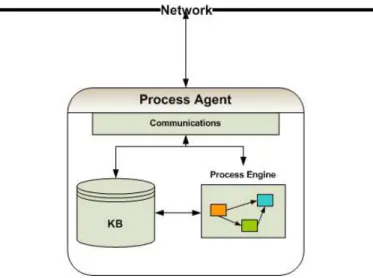
4.1.1 The Process Agent . . . 44
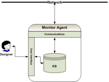
4.1.2 The Monitor Agent . . . 49
4.3 Conclusions . . . 55
5 A Process Model Specification 57 5.1 Description of the Process Model . . . 58
5.1.1 Process . . . 58
5.1.2 Flow Control . . . 60
5.1.3 Transition . . . 61
5.1.4 Activity . . . 61
5.2 Error Control . . . 62
5.3 Conclusions . . . 63
6 Implementation of the System 65 6.1 System Ontologies . . . 66
6.1.1 Concepts Ontology . . . 66
6.1.2 Process Ontology . . . 67
6.1.3 Agent Ontology . . . 76
6.1.4 Communication Ontology . . . 79
6.2 The Implemented MAS . . . 83
6.2.1 The Process Agent . . . 86
6.2.2 The Monitor Agent . . . 91
6.3 The Process Engine . . . 95
6.4 The Process Editor . . . 99
6.5 EPS System Implementation . . . 101
6.5.1 Conveyor Implementation . . . 105
6.5.2 Crane Implementation . . . 106
6.5.3 Buffer Implementation . . . 108
6.5.4 Driller Implementation . . . 108
6.5.5 EPS Monitor Agent . . . 109
6.6 Testing Scenario . . . 110
7 Conclusions and Future Work 113 7.1 Conclusion . . . 113
7.2 Future Work . . . 116
A Custom Activities 117
B EPS Ontology 119
C An Example Process 125
List of Figures
2.1 An abstract model of a manufacturing system. . . 6
2.2 Activities to create a manufacturing control architecture. . . 7
2.3 CoBasa consortia formation. . . 13
2.4 The traditional control architectures. . . 14
3.1 Some of the communication protocols specified by FIPA for ACL messages. 22 3.2 The JADE GUI main window. . . 24
3.3 An example of a RDF graph. . . 27
3.4 An example of reasoning. . . 33
3.5 The Jena ontology model structure. . . 34
3.6 The Prot´eg´e GUI. . . 35
3.7 The BPM life-cycle. . . 36
3.8 A cross functional process. . . 37
4.1 The basic architecture of the process-based system. . . 43
4.2 The architecture of the Process Agent. . . 44
4.3 The default communication interactions of the Process Agent. . . 45
4.4 Information flow inside the Process Agent. . . 47
4.5 External queries between the Process Agents. . . 49
4.6 The architecture of the Monitor Agent. . . 50
4.7 The base EPS architecture. . . 51
4.8 A Process Agent configured to control a manufacturing module. . . 52
4.9 An example of external skill execution. . . 53
4.10 The EPS control architecture. . . 55
5.1 The structure of a process. . . 58
5.2 A detailed view of a process. . . 59
5.3 The actor-process relationship. . . 59
5.4 A detailed view of an activity. . . 61
5.5 Error control types. . . 62
6.1 The relationship between the different ontology domains in the system. . . . 66
6.2 The concepts ontology class diagram. . . 66
6.4 The flow control class diagram. . . 73
6.5 The agent ontology class diagram. . . 77
6.6 The communication ontology class diagram. . . 80
6.7 The initiation of the Process Agent. . . 87
6.8 The finalization of the Process Agent. . . 88
6.9 The shared model tree. . . 89
6.10 Interactions between Process Agents and Proxy Agents. . . 90
6.11 The GUI associated to the Monitor Agent. . . 91
6.12 TheOntology tab. . . 92
6.13 TheProcesses tab. . . 92
6.14 The menus in the GUI of the Monitor Agent. . . 93
6.15 The SPARQL editor in the Monitor Agent. . . 94
6.16 The OWL message chooser in the Monitor Agent. . . 95
6.17 The conversion of a process described in OWL to JADE behaviours. . . 96
6.18 The KB tree inside a process engine. . . 97
6.19 A new activity as a subclass of theActivity class. . . 99
6.20 The main window of the Process Editor. . . 100
6.21 The MOFA France kit. . . 102
6.22 The requests to exchange information with the simulator. . . 103
6.23 A generic deployment process. . . 104
6.24 A diagram of the transportation skill in conveyors. . . 106
6.25 A diagram of the transportation skill in cranes. . . 107
6.26 The EPS Monitor Agent GUI. . . 109
6.27 The first testing scenario with the initial shop floor configuration. . . 110
6.28 The first testing scenario with the shop floor configuration after a change. . 111
6.29 The second testing scenario. . . 112
B.1 UML class diagram of the equipment. . . 120
B.2 UML class diagram of the modules and skills. . . 121
B.3 UML class diagram of products and plans. . . 122
C.1 A section of the example process, as seen in the editor. . . 126
List of Tables
2.1 EPS qualitative versus quantitative features. . . 12
3.1 The FIPA parameters for ACL messages. . . 21
6.1 Common processes to all the modules. . . 103
6.2 The skills of the conveyor agent. . . 105
6.3 The skills of the crane agent. . . 106
6.4 The skills of the buffer agent. . . 108
6.5 The skills of the driller agent. . . 108
A.1 The set of activities contained in the Default library. . . 118
A.2 The set of activities contained in the EPS library. . . 118
Listings
3.1 An example of OWL. . . 29
3.2 An example of a SELECT query. . . 30
3.3 An example of a CONSTRUCT query. . . 30
3.4 An example of an ASK query. . . 31
3.5 An example of a DESCRIBE query. . . 31
3.6 An example of an INSERT/DELETE query. . . 32
6.1 An example of an ACL message containing a SPARQL query. . . 84
6.2 Java code to convert Jena ontology models to String. . . 84
6.3 Java code to convert ontology String representations to Jena ontology models. 85 6.4 An example of an ACL message containing an OWL content. . . 86
6.5 Template to implement an activity. . . 98
6.6 Template to implement an activity in the editor. . . 100
Acronyms
ACC Agent Communication Channel
ACL Agent Communication Language
AEI Advanced Enabling Interface
AI Artificial Intelligence
AID Agent Identifier
AMS Agent Management System
API Application Programming Interface
BDI Belief-Desire-Intention
BPM Business Process Management
BPMS Business Process Management System
BPR Business Process Reengineering
CIM Computer Integrated Manufacturing
CPU Computer Processor Unit
DF Directory Facilitator
DL Description Logic
EAS Evolvable Assembly Systems
EPS Evolvable Production Systems
EUPASS Evolvable Ultraprecision Assembly Systems
FIPA Foundation for Intelligent Physical Agents
GA Genetic Algorithm
GUI Graphical User Interface
HMS Holonic Manufacturing Systems
IT Information Technology
JADE Java Agent Development Framework
KB Knowledge Base
KIF Knowledge Interchange Format
KQML Knowledge Query and Manipulation Language
KSE Knowledge Sharing Effort
MAS Multi-Agent Systems
PLM Product Lifecycle Management
OWL Web Ontology Language
RDF Resource Description Framework
RDFS Resource Description Framework Schema
RMS Reconfigurable Manufacturing Systems
SL Semantic Language
SME Small and Medium Enterprises
SOA Service-Oriented Architecture
SPARQL SPARQL Protocol and RDF Query Language
SQL Structured Query Language
SWRL Semantic Web Rule Language
UML Unified Modelling Language
URI Uniform Resource Identifier
VE Virtual Enterprise
WADE Workflow Agents Development Environment
WfMC Workflow Management Coalition
XML eXtensible Markup Language
Chapter 1
Introduction
When faced with unexpected faults, last minute order changes or totally different product order needs, manufacturing companies require continuous reconfigurations and adaptations in their shop floors [Barata, 2005]. This may be a problem in terms of costs and time spent,
so a solution is needed in order to provide an advantage to manufacturing companies. So, to keep competitive, companies aim to improve their flexibility and agility while maintaining
their productivity and quality [Leit˜ao and Restivo, 2006].
The terms flexibility and agility are used separately, since they mean separate con-cepts: A flexible company is one that can adapt itself to produce a certain range of products efficiently, which means the products must be known prior to the system design or must not
be very different from each other, while an agile company operates efficiently in a dynamic and uncertain environment. There is a considerable amount of research about manufactur-ing in the area of flexibility [Gullander, 1999, Vos, 2001, ElMaraghy, 2005] and also in the
area of agility [Huff and Edwards, 1999, Leitao, 2004].
Currently, tendency goes to research systems that attain agility by using self-organ-isation and self-adaptation so that the response to changes in the manufacturing needs may be achieved with high productivity and low costs. Distributed Systems like
Multi-Agent Systems (MAS) provide a solution for this situation, distributing the control of the system to a number of autonomous entities, reducing the complexity of the entire system
CHAPTER 1. INTRODUCTION
agent-based manufacturing, Holonic Manufacturing Systems (HMS), Reconfigurable Manu-facturing Systems (RMS), Evolvable Production Systems (EPS) and Evolvable Production Systems (EPS) [Ribeiro et al., 2008].
1.1
Objectives
The work described in this thesis falls under the domain of the EPS paradigm, which
gets inspiration from areas like complexity theory, artificial life, autonomic computing, agents and self-organisation [Barata et al., 2007]. All of these areas affected, in one point
or another, the objectives defined for this work. It was given more emphasis to the areas of agents and self-organization, since they were a central part of the thesis here presented, although the other areas also influenced some of the decisions during the planning.
The system described in this document aims to be an agile system with some self-organization capabilities, able to control shop floor resources in a dynamic way, so that
when sudden changes in production orders or reorganization of the physical placement of the machines take place, it is able to adapt itself or be easily reconfigured without the
need to be reprogrammed. In order to attain the desired level of flexibility and agility, the proposed system is set to fulfil the following requirements:
• Modularity - The modularization of manufacturing components assigns specific
tasks to specific modules making them specialized and the system scalable. The combined efforts of two or more modules can result in a more complex behaviour. One analogy to this kind of reasoning is the human brain, where certain areas are
specialized in a certain task and the combined effort of such tasks can result in more complex human actions, for example, eye coordination and several muscles
coordina-tion areas can combine in order to externalize the emocoordina-tion of sadness [Dam´asio, 2003]. As stated before, this reduces the overall programming complexity of the entire ar-chitecture.
• Reduce programming effort - The act of reprogramming entire systems in order
to cope with production changes or the addition or removal of a manufacturing
CHAPTER 1. INTRODUCTION
• Re-usability - Manufacturing modules should be reused for as long as possible
[Barata, 2005]. This implies the need to support updates and reconfiguration of their behaviours, thus adapting to new scenarios.
• Self-Organization- Modularized components have to be able to organize themselves
in order to achieve certain goals, which may require the execution of complex tasks involving multiple modules. Also, modules have to respect each one’s restrictions and
needs as best as possible. This amounts to a self-organized system in which each constituent has an active part in it by exchanging information and reasoning over it.
In the approach chosen, the objective was the development of a process-based system,
taking examples from the area of Business Process Management (BPM) which addresses many problems similar to the ones already cited, like the need to adapt to change in
de-mands or the requirement for shorter life-cycles [Ryan K.L. Ko, 2009]. The system planned for this thesis is a Multi-Agent Systems (MAS) where each agent is able to execute pro-cesses1 containing a certain set of activities. This approach would allow the reduction of
programming effort and encourage re-usability.
Each constituent of the system (conveyors, cranes, manufacturing cells, etc.),
repre-sented by an agent, becomes a module with a certain degree of reasoning. This decentralized approach allows a modularization of the system and self-organization. Also, this modular
point of view provides emergent properties to the system, that is, properties that cannot be predicted by analysing each part of the system separately. The smaller the parts and the less work entrusted to them, and therefore the higher granularity, the easier it is to
coordinate and structure the system or change it altogether, providing it with a high degree of agility [Maraldo et al., 2006].
When developing Evolvable Production Systems (EPS), the highly dynamic life-cycle is the main problem to be considered, which, of course, contains some other problems itself,
like the creation and re-engineering of systems (creation, dissolution and changing of a given production cell), the development of an architecture for an individual module and the development of an architecture that supports a society of modules [Onori et al., 2005].
These problems were addressed by the author as best as possible in the defined architecture.
1In the context of this work, processes and agent behaviours mean the same thing, as behaviours
CHAPTER 1. INTRODUCTION
1.2
Thesis Outline
This thesis is divided in seven chapters: Introduction, Manufacturing Systems: A State-of-the-Art,Supporting Concepts and Technologies, A BPM-Based Architecture for EPS, A Process Model Specification, Implementation of the System and Conclusions and Future Work.
The current chapter gives a brief introduction to the research problem, states the objectives outlined for this work and identifies some of the most important concepts used
in this thesis.
Chapter 2 gives an overview of the state-of-the-art in manufacturing systems along
with the current state of research in this area. Flexible and agile manufacturing systems are described in this chapter, as well as Evolvable Production Systems (EPS), which is the basis of this work.
Chapter 3 introduces the concepts used in the implementation of the work here de-scribed. Agents, ontologies and Business Process Management (BPM) are explained there.
This chapter also gives an overview of the technologies used in the actual implementation of this thesis.
Chapter 4 is one of the main chapters in this thesis by presenting the generic multi-agent architecture that works under the BPM paradigm. In that chapter it is also explained the application of said architecture to the manufacturing environment, by detailing a
higher-level EPS architecture.
Chapter 5 describes the theory behind the actual execution of processes, by detailing
the model created for this effect. This is the most important chapter in this thesis, since all the work done is based on the technology in it described.
Chapter 6 describes the actual implementation of the architecture defined in Chapter 4
as well the implementation of the process model defined in Chapter 5. Later, it details how the architecture was configured to create the higher-level EPS architecture, also presented
in Chapter 4. Lastly, the testing scenarios used in this work, as well as some results, are also presented.
Chapter 2
Manufacturing Systems: A
State-of-the-Art
Nowadays, the needs are for highly customized products, with a short life-cycle, high quality and low costs. So, and with the increase of competitiveness, companies constantly need to
achieve higher productivity, flexibility and agility in order to stay in the market.
Companies that can not solve their problems internally, tend to look for cooperation amongst themselves in order to increase competitiveness by creating Virtual Enterprises
(VEs) or other types of alliances, fulfilling specific demands. This is the case of many Small and Medium Enterprisess (SMEs) that have poor engineering resources.
The use of competitive and up-to-date technologies is also one of the key factors for
companies to stay on the market, and is a major topic in this thesis. With the creation of Computer Integrated Manufacturing (CIM), Flexible Manufacturing Systems (FMS) or different control architectures, new, cheaper and innovative ways of creating manufacturing
systems were found gave companies a boost when competing with each other. Studies and works in this area also gave birth to concepts such as agile manufacturing or Evolvable
Production Systems (EPS) and Evolvable Assembly Systems (EAS).
This chapter contextualizes the work in this thesis, introducing to manufacturing sys-tems and giving an overview of the evolution in this area. It also describes new approaches
CHAPTER 2. MANUFACTURING SYSTEMS: A STATE-OF-THE-ART
2.1
Manufacturing Systems
The chosen definition for the process of manufacturing may be found in [Groover, 2007]. According to this book:
Manufacturing can be defined as the application of physical and chemical pro-cesses to alter the geometry, properties and/or appearance of a given starting material to make parts or products; manufacturing also includes the joining of multiple parts to make assembled products. The processes that accomplish manufacturing involve a combination of machinery, tools, power and manual labour.
Consequently, manufacturing systems, during the production process, involve ma-chines, tools, material-handling systems and humans in charge of manual labour. The
pro-duction process has also inputs of raw materials, information, energy, the guidelines that tell the system how to produce, product demands and external disturbances [Leitao, 2004]. This results in finished products, along with new information about performance or the
current status of the system. Also, unused or useless material comes in the form of waste. An abstract model of a manufacturing system can be seen in Figure 2.1.
CHAPTER 2. MANUFACTURING SYSTEMS: A STATE-OF-THE-ART
To design manufacturing systems, all the factors shown in the previous figure need to be taken into account. Many of these factors determine how manufacturing control architectures are created. Figure 2.2 shows the steps required to design a control structure
and where external factors influence that design.
Figure 2.2: Activities to create a manufacturing control/supervision architecture, found in [Barata, 2005], which are the definition of requirements, methodology creation and architecture creation. Each activity depends on external factors.
Requirements, depending on several external factors, need to be defined in order
to design the control structure. These requirements are applied to the creation of the methodology that will be used in the architectural planning of the control and supervision
structure.
A planning like the one in Figure 2.2 may be executed several times, because the control structure defined at one time may not be suitable for future products [Barata, 2005].
Therefore, the manufacturing environment is in constant evolution. This evolution started at the end of the nineteenth century with the paradigm ofCraft Production, where products were created to suit a single customer needs, using highly skilled workers and simple, but flexible tools [Piore and Sabel, 1984].
CHAPTER 2. MANUFACTURING SYSTEMS: A STATE-OF-THE-ART
After the late 1970s, studies were conducted to discover why the Japanese production techniques were more successful than the ones used in the western world. Such studies con-cluded that an efficient manufacturing technique was being used in Japan. This technique
was later calledLean Manufacturing [Womack et al., 1990]. This concept relies on the prin-ciple of delivering high quality and low cost products with minimal waste. Waste is any
activity that absorbs resources and does not add any value to the production [Barata, 2005].
With the constantly rising demand in the market for more personalized products at lower prices, while keeping the same quality levels, came the concept ofMass Customization [Pine and Davis, 1999]. This can be defined as a fast increase in the variety and customiza-tion of products while keeping the same costs. At its limit it is the mass produccustomiza-tion of individually customized products [Barata, 2005].
The integration of CIM in the manufacturing environment allowed new approaches to be designed. Flexible Manufacturing and Agile Manufacturing are two of such approaches that mark the latest years of research in the manufacturing domain. Since these concepts
also fall in the domain of this thesis, they are described more thoroughly in Sections 2.2 and 2.3.
Another concept worth referring, is Business Process Reengineering (BPR), which
is mainly an organizational philosophy applied in the higher management aspects of a manufacturing company. It has yet no application in the shop floor [Barata, 2005]. Ideally,
a company should apply this concept in all its levels but this does not happen. BPR specifies how and when to redesign old processes, eliminating waste [Victor and Boynton, 1998]. Discussion on this subject will be picked up later in this document, since it is closely
related to some of the concepts here used.
2.2
Flexible Manufacturing
With the advent of CIM, which introduced computerized control in the manufacturing environment [Browne et al., 1988, Camarinha-Matos et al., 1995, Miller and Walker, 1990],
concepts like Flexible Manufacturing Systems (FMS) appeared to deal with the varying products and demands, in order to increase the competitiveness of companies throughout
CHAPTER 2. MANUFACTURING SYSTEMS: A STATE-OF-THE-ART
A more specific definition may be found in the book Flexible Manufacturing System [Shivanand, 2006], where it is stated that:
A flexible manufacturing system (FMS) is an arrangement of machines [...] interconnected by a transport system. The transporter carries work to the ma-chines on pallets or other interface units so that work-machine registration is accurate, rapid and automatic. A central computer controls both the machines and transport system.
The adoption of the FMS approach meant that machines in a given system would be flexible enough to perform a wide range of tasks, which brought many advantages to
the manufacturing domain, like increasing of productivity, decreasing of production costs, reduction of inventory and stocks and superior quality [Rembold et al., 1993, Ranky, 1990].
Even though machines were able to perform a certain range of tasks, they were never excellent performers performers at any of the individual tasks. This was one of the downsides
of FMS. The systems would be flexible enough to cope with several different problems but would not resolve them in the best way possible. Another problem was that the FMS was
flexible while producing a range of known products but, when it came to produce something from a different and previously unknown product family, it became inflexible [Leitao, 2004], because agility was not a concern at the time and the life cycle support lacked from the
concept [Barata, 2005].
2.3
Agile Manufacturing
Nowadays, the unpredictability of the factors that influence the manufacturing domain, like the markets or society itself, caused for the research of a new and innovative way to handle
systems. The solution for these problems came in the form of agile manufacturing, which was first mentioned in a report by Nagel and Dove [R. Nagel, 1992].
Agile manufacturing is a step forward to the previously mentioned FMS and similar systems. Even though a FMS can be used to produce a wide range of products and can
accommodate some internal changes, they only work in a predictive environment. This is not the case if the system is agile, since agile manufacturing deals better with things that cannot be controlled [Maskell, 2001] or, in other words, uncertain environments.
CHAPTER 2. MANUFACTURING SYSTEMS: A STATE-OF-THE-ART
is a company-wide effort, where all the areas need to be integrated in order to obtain the best results. A successful implementation of an agile manufacturing system requires the following points [Barata, 2005]:
• Political decisions - Regulations are needed to help cooperation and innovation.
Also, political decisions may affect the bounds in which a company should work.
• Business cooperation- Companies should be able do diversify cooperative
relation-ships by creating virtual partnerrelation-ships, in which they share their business competencies with each other, providing focused services and products to the customer.
• Customer focus - It is important to create a philosophy to focus the company on
the customer. Creating solutions to add value to products or services is vital for
companies to gain the attention of the customer, enabling more demand and higher profit.
• Information technology- In all areas of an agile company, computational support
is essential, from creating a virtual partnership with another company to controlling
the shop floor.
• Processes re-engineering - Involves identifying what processes must exist and
redesigning them if needed. Process-centric approaches in companies are widely used
nowadays. Since this is one of the main subjects of this thesis, this concept will be further discussed in Section 3.3.
• New work organization- An organization based on teams and cooperation, with
skilled and autonomous workers must be implemented. These workers need to be
highly trained, since their competences may fall under several domains within the companies and autonomy is highly needed.
• New agile shop floor strategies - As stated before, the current approaches, like
FMS, do not deal well with uncertain environments. A new strategy is needed to cope with these problems, like EPS. Also, a careful study of all the entities involved
in the process of manufacturing is needed in order to create a new methodology that integrates them.
• Willingness to change- All the actors involved must be constantly monitoring the
CHAPTER 2. MANUFACTURING SYSTEMS: A STATE-OF-THE-ART
2.4
Evolvable Production Systems
In recent years, a new concept of manufacturing systems was created, even though it
has yet no actual implementation in the real manufacturing world: the Evolvable Pro-duction Systems (EPS)1. Much research on this subject was already accomplished by
many different authors [Frei and Barata, 2008, Barata and Onori, 2006, Shen et al., 2006, Maraldo et al., 2006].
An EPS is a system that can dynamically adapt itself to new products and production scenarios. This means that the addition and removal of manufacturing modules and changes in the production orders stimulate the system to adapt to new scenarios at run-time, without
the need to completely stop for reprogramming. This can be achieved by designing systems that can integrate any form or type of equipment, which, in turn, must be broken down into
smaller, process oriented components. Ontologies and Knowledge Bases (KBs) need to be created to structure the assembly process. Once the process requirements are captured, an
assembly platform will be attainable. This platform is linked to the product designers, in order for them to know the system capabilities and the constraints related to the product design. This is a highly adaptable and re-configurable system [Maraldo et al., 2006].
The EPS modular point of view provides emergent properties to the system, which are properties that cannot be predicted by analysing each part of the system separately.
The smaller the parts and the less work entrusted to them, the easier it is to coordinate and structure the system [Shen et al., 2006, Maraldo et al., 2006].
Studies concluded that EPS needed a certain set of qualitative features to be de-scribed, as can be seen below [Shen et al., 2006, Barata and Onori, 2006]:
• Module- Represents any unit that can process an operation and integrates a specific
interface. A module may represent a single manufacturing component, like a driller,
or represent a coalition of several components, like a cell.
• Granularity - The lowest level of device considered within a reference architecture.
For instance, if a robotic arm and a gripper are considered individually, they may communicate and new characteristics may arise, like flipping an object. The lower the level, the higher the emergence.
1In this work, most of the references presented for EPS call it Evolvable Assembly Systems (EAS).
CHAPTER 2. MANUFACTURING SYSTEMS: A STATE-OF-THE-ART
• Plugability - The ability to add or remove system components. This aspect is very
important when considering a system that may need new manufacturing resources when a new product order is issued.
• Reconfigurability - The ability to rearrange available system components to
per-form new, but pre-defined, operations when a new module is added or to discard
operations when an existing module is removed.
• Evolvability - If a fullyreconfigurable system platform exhibits an emergent
behav-iour which introduces new or refined levels of functionality. This may be achieved by applying the previously stated points to a system.
In practice, in order to comply with the qualitative features above, an EPS containing
a certain set of quantitative features to address each required quality has to be implemented. Table 2.1 adapted from [Shen et al., 2006, Barata and Onori, 2006] shows these features.
Table 2.1: EPS qualitative versus quantitative features.
EPS qualitative features EPS quantitative features
Evolvability-conformity Skills repository and Management Plugability and Reconfigurability - control
specifications Module description/blueprint
Plugability-user requirements Application guidelines
Granularity-Safety conformity Safety certification procedures Evolvability and Safety Rules related to emergent behaviour Plugability-practical implementation EPS ”wrapper” solution: hardware Evolvability-practical implementation EPS ”wrapper” solution: software
Evolvability and Precision EPS architecture approach (granularity to lowest level)
An EPS system requires a virtual repository to store all the structures needed for
users to comply with specifications and also the reference architecture. Specifications must be added in order to attain plugability, so that external users can import their equipment to
CHAPTER 2. MANUFACTURING SYSTEMS: A STATE-OF-THE-ART
and with the hardware, so wrapper interfaces, also called Advanced Enabling Interface (AEI), need to be created. This also implies that legacy components may be adapted to the EPS format. Finally an extremely well defined reference architecture has to be implemented.
The main building blocks of an EPS are the modules, which may represent physical components of the architecture or aggregations of these components that present the
emer-gent properties resulting from such aggregation. Physical modules must describe the set of characteristics of the components they represent and should also capture the behaviour of
the component and realize the necessary control actions that must be issued for the behav-iour to be accomplished [Onori et al., 2005]. These behavbehav-iours are viewed by the system as
skills and each skill represents the capability of the module to perform a certain task. A skill execution may involve performing a sequence of control actions offered by the component controller. The behaviours that emerge out of the interaction of the individual modules
represent the complex functionalities, or complex skills, of the system [Onori et al., 2006]. These complex skills are offered by higher level modules representing the aggregation of
other modules.
An example of an EPS is CoBasa [Barata, 2005]. Figure 2.3 shows the basic
func-tioning of this system.
CHAPTER 2. MANUFACTURING SYSTEMS: A STATE-OF-THE-ART
The CoBasa architecture is based on consortia formation, where each module is placed in a cluster waiting for a re-engineering opportunity. When this opportunity arises, several consortia are created between the modules, each with a specific operation plan that fits in
the production.
2.5
Manufacturing Controls
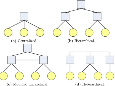
One of the things that influences the final performance of manufacturing systems is their control architectures. Traditionally, the architectures can be classified as centralised,
hi-erarchical, modified hierarchical and heterarchical [Dilts et al., 1991]. These architectures can be seen in Figure 2.4.
(a) Centralized. (b) Hierarchical.
(c) Modified hierarchical. (d) Heterarchical.
Figure 2.4: The traditional control architectures: centralized, hierarchical, modified hierarchical and heterarchical.
The centralized architecture consists of one central node that coordinates all the in-ferior nodes. This approach provides simpler coordination issues, since most of the logic is
CHAPTER 2. MANUFACTURING SYSTEMS: A STATE-OF-THE-ART
The hierarchical architecture releases the central node from most of the complexity by transferring it to inferior nodes. This can provide adaptive behaviours and can reach a nearly optimal performance under stable situations but has poor fault tolerance.
The modified hierarchical architecture derives from the hierarchical architecture by adding connections between the inferior nodes. This aims to improve disturbance responses
and provides better expandability to the system.
The heterarchical architecture takes the central node out of the picture, distributing
control over the inferior nodes. The advantage is the great flexibility of this type of control but, on the other hand, the absence of a central node can render impossible an appropriate control over the system.
2.6
Conclusions
Even though the technological evolution of manufacturing covers many concepts, some of
them described in the previous sections, the work of this thesis was solely to create and study a new approach in the context EPS. And, even then, implementing a full EPS with all
the described features would require an amount of work too great for a master thesis. This chapter was written only to contextualize the reader in the current state of manufacturing
systems, giving the necessary background to this work.
As already stated, this work evolved around a process-based approach which eases the configuration of shop floor control. This does not mean that it is turned into a simple task,
as configuring a full-fledged EPS would still require a great amount of labour and many other considerations beyond what was achieved through the course of this work. This thesis
Chapter 3
Supporting Concepts and
Technologies
The development of this thesis required the support of some concepts and technologies. The motto ”Standing on the shoulders of giants” was taken seriously and a great deal of effort was spent in studying different approaches and technologies to implement this work,
culminating in the choice of the ones that actually support this framework.
The purpose of this chapter is to introduce the reader to these underlying concepts
in order to have a better comprehension of the following chapters and of the reasons that influenced their choices. What is described in this chapter is just an introduction to the
concepts and the references scattered throughout the text should be consulted for better insight on the subjects.
This chapter firstly explains the idea of Multi-Agent Systems (MAS) and the used technology for their implementation, Java Agent Development Framework (JADE).
Sec-ondly, the ontology concept is described. In the context of this thesis, the used ontology language was Web Ontology Language (OWL), which is based on Resource Description Framework (RDF). Also, for querying and asserting facts on ontological KBs, SPARQL
Protocol and RDF Query Language (SPARQL) was used, along with its variant that allows the update of KBs. All of these languages and respective implementation technologies, Jena
CHAPTER 3. SUPPORTING CONCEPTS AND TECHNOLOGIES
3.1
Multi-agent Systems
The traditional manufacturing control systems do not support efficiently the current
re-quirements imposed to the manufacturing systems [Leit˜ao and Restivo, 2006]. Leit˜ao also states that, because of the increase of powerful, inexpensive and widely available compu-tational resources, the architectures evolved from centralised to distributed and dynamic
approaches.
Multi-agent systems, being distributed systems by nature, tend to be used now in
or-der to solve the flexibility problems in manufacturing systems. Many researches and studies have been focused in this area [Barata and Camarinha-Matos, 2002, Barata et al., 2005,
Colombo et al., 2006].
3.1.1
Individual Agents
The definition of an agent is a controversial subject, as there is no consensus about what the
exact definition is. Nonetheless, in this work, the adopted definition was [Wooldridge, 2002]:
An agent is a computer system that is situated in some environment, and that is capable of autonomous action in this environment in order to meet its design objectives.
This means agents need to reason about their surrounding environment in order to take an autonomous action. Even though this may mean the agents are intelligent, a simple
program that gathers information, reasons over it and takes an action, like, for example, the software that detects the Computer Processor Unit (CPU) temperatures and fires an alarm when they are too high, can hardly be described as an intelligent program. Below,
a list of the kinds of capabilities one might expect from an intelligent agent is presented [Wooldridge and Jennings, 1995]:
• Reactivity - The capability an agent has to react to environment changes in order
to satisfy its objectives.
• Pro-activeness- The capability of agents to have a goal-directed behaviour in order
to achieve their objectives.
• Social ability - The capability agents have of interacting with each other and to
CHAPTER 3. SUPPORTING CONCEPTS AND TECHNOLOGIES
Creating purely reactive or pro-active systems is not very difficult as they are made all the time, but a system that balances these characteristics is the key for an intelligent agent functioning. Also, the social ability is not only the passing of bit streams from an agent to
another, but also their capability of negotiating and cooperating to achieve a common goal. Programmers that use object-oriented programming may think that agents are more
or less the same but there are differences [Wooldridge, 2002]:
• Agents have a stronger notion of autonomy than objects and they decide for
them-selves whether or not to perform a particular action on external request.
• Agents are capable of flexible behaviour, unlike objects.
• A multi-agent system is inherently multi-threaded, with each agent having at least
one thread of control.
There may also exist some confusion between the concept of agency and expert
sys-tems but there are differences [Wooldridge, 2002]:
• ’Classic’ expert systems are not coupled to any environment to act in. They rather
act through a user as a ’middleman’.
• Expert systems are not generally capable of flexible behaviour (reactive, proactive
and social).
3.1.2
Agent Typologies
Agents can be classified into three architectural types, according to their attitude towards the surrounding environment [Wooldridge and Jennings, 1994]: deliberative, reactive and
hybrid.
3.1.2.1 Deliberative Agents
CHAPTER 3. SUPPORTING CONCEPTS AND TECHNOLOGIES
The most well-known architecture inside the deliberative agent paradigm is the Belief-Desire-Intention (BDI) architecture, which contains data structures loosely corresponding to these mental states [Wooldridge, 2000]. The BDI architecture includes the agent knowledge
about the environment (beliefs), preferred states to achieve in the long-term (desires) and planned decisions to be made to complete a plan (intentions).
3.1.2.2 Reactive Agents
Agents that fall inside the reactive paradigm do not contain an internal representation of
the surrounding environment. They merely react to the environment without reasoning over it [Wooldridge, 2002]. The ideas behind this type of architecture are [Brooks, 1991b, Brooks, 1991a]:
• Intelligent behaviour can be generated without explicit representations of the kind
that symbolic Artificial Intelligence (AI) proposes.
• Intelligent behaviour can be generated without explicit abstract reasoning of the kind
that symbolic AI proposes.
• Intelligence is an emergent property of certain complex systems, where the interaction
of several simple and reactive nodes may generate more complex behaviours.
3.1.2.3 Hybrid Agents
The hybrid architecture is an alternative to the limitations imposed by both the deliberative
and reactive architectures. Purely reactive agents are not capable of implementing a goal-oriented behaviour, while deliberative agents may become incapable of rapidly responding to external stimuli.
This hybrid type of architecture merges the advantages of both the deliberative agents and the reactive agents. This is accomplished by creating an hierarchy of layers in the
agents [Wooldridge, 2002]. Each one of these layers may represent a reactive or a pro-active component. There should be a minimum of two layers each representing a different
CHAPTER 3. SUPPORTING CONCEPTS AND TECHNOLOGIES
3.1.3
Agent Communication
Since a single agent represents only a part of a multi-agent system, agents must communicate
so that all the parts of the system may interact and achieve common goals. To attain this purpose, the agents need to understand each other via communication languages and ontologies. Since ontologies are one of the main subjects in this thesis, they are described
in detail in Section 3.2.
The Agent Communication Language (ACL) was directly influenced by the Speech
Act theory, which treats communication as an action. One main ACL was created by the DARPA-funded Knowledge Sharing Effort (KSE): The Knowledge Query and Manipulation Language (KQML). This language was intended to be an envelope language for agent
messages, in which the agent can state the intended use of the message. The contents of the messages did not matter for this language. KSE released the Knowledge Interchange
Format (KIF) for the description of the contents of the messages.
Table 3.1: The FIPA parameters for ACL messages. Adapted from [FIPA, 2002a]
Parameter Description
performative Denotes the type of the communicative act of the ACL message.
sender Denotes the identity of the sender of the message, that is, the name of the agent of the communicative act.
receiver Denotes the identity of the intended recipients of the message.
content
Denotes the content of the message; equivalently denotes the object of the action. The meaning of the content of any ACL message is intended to be interpreted by the receiver of the message.
language Denotes the language in which the content parameter is expressed.
ontology Denotes the ontology(s) used to give a meaning to the symbols in the content expression.
protocol Denotes the interaction protocol that the sending agent is employing with this ACL message.
conversation-id Introduces an expression which is used to identify the ongoing se-quence of communicative acts that together form a conversation.
CHAPTER 3. SUPPORTING CONCEPTS AND TECHNOLOGIES
it also includes a normative description of a set of high-level interaction protocols, such as requesting information and contract-net [Labrou et al., 1999]. This language was used throughout the implementation of this work, so it deserves a little more explanation. A
message in this language contains a set of one or more message parameters. The most important parameters are defined in the Table 3.1.
The table takes out one important feature of this type of messages: the ability to
contain user-defined fields, which allows a user to add fields to a message that make sense in the scope of his work. Also, theperformative is very important, which defines the com-municative act attached to the message. Comcom-municative acts define whether the message is a request, a proposal or any other type defined in the FIPA specifications [FIPA, 2000].
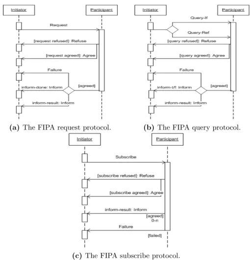
(a) The FIPA request protocol. (b) The FIPA query protocol.
(c)The FIPA subscribe protocol.
CHAPTER 3. SUPPORTING CONCEPTS AND TECHNOLOGIES
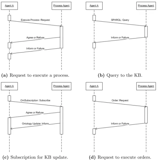
FIPA-ACL supports a series of message exchange protocols, which use the commu-nicative acts to differentiate the messages during the exchange. In a given protocol the conversation-id should always be the same in order for the agents to know that the mes-sages belong to the same conversation. In the context of this work, only three protocols were considered, even though there are many more specified by FIPA. TheRequestprotocol consists on an agent requesting another agent to perform a certain action, which may be successful or not [FIPA, 2002c]. The Query protocol is used when an agent needs to be queried for information at a given moment [FIPA, 2002b]. TheSubscribe protocol allows an agent to request a receiving agent to perform an action on subscription and subsequently when the referenced object changes [FIPA, 2002d]. All of these protocols are shown in
Figure 3.1.
3.1.4
JADE
MAS can be implemented using regular programming languages, such as Java, by
imple-menting the needed features for agent communication, ontology support, yellow and white pages service, message encoding, parsing and transport and agent life-cycle management
ser-vices [Leitao, 2004]. Several platforms that support such features are already implemented and Java Agent Development Framework (JADE) is among them [JADE, 2010].
JADE is a framework for creating and managing agents that is compliant with the FIPA specifications. It provides a naming service, yellow-page service, message transport
and parsing service, and a library of FIPA interaction protocols. Additionally, JADE pro-vides the mandatory components defined by FIPA to manage the agent platform, which are the Agent Communication Channel (ACC), the Agent Management System (AMS), and
the Directory Facilitator (DF). The DF is a particularly useful service, since it provides yellow pages services needed to find other agents and services in the network by sharing the
information it contains when queried.
An agent in JADE must be able to carry out several concurrent tasks in response to
different external events. In order to make agent management efficient, every JADE agent is composed of a single execution thread where all its tasks are modelled. These tasks can be
CHAPTER 3. SUPPORTING CONCEPTS AND TECHNOLOGIES
The communications between agents are performed through ACL messages. JADE provides the FIPA Semantic Language (SL) content language and the agent management ontology, as well as the support for user-defined content languages and ontologies. Also, the
FIPA-ACL message exchange protocols and message parameters, described in the previous section, are also supported by JADE. Some of the protocol implementations have simplified
versions where less messages are exchanged for optimization purposes. In most of the cases, there is an omission of the section of the protocols where an acceptance or refusal is made.
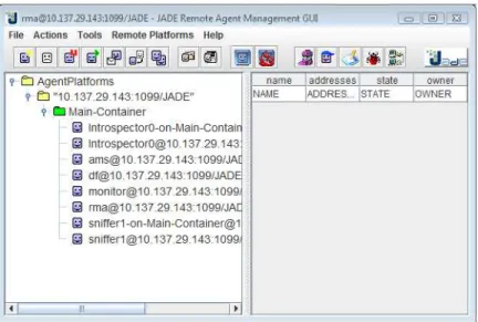
JADE also provides a generic Graphical User Interface (GUI) that may be used to
monitor active agents and communications between them, among other details. It can also be used to influence the system itself by creating and killing agents as well as performing
other actions. This GUI is shown in Figure 3.2. The JADE GUI comes with several useful tools to gather specific information from the deployed agents, which include the sniffer
agent, responsible for tracking all the messages sent in the system, and the introspector agent, which may inspect the states of the behaviours inside the agents.
Figure 3.2: The JADE GUI main window, where the user may get essential informa-tion about the currently running agents.
Since the JADE framework is implemented in Java, it is possible to integrate it
CHAPTER 3. SUPPORTING CONCEPTS AND TECHNOLOGIES
3.2
Ontologies
In philosophical terms ontology is the science of the kinds and structures of objects, prop-erties, events, processes and relations in every area of reality and it is often used by philoso-phers as a synonym of metaphysics [Smith, 2009]. Later, ontologies became popular in
other areas outside philosophy, like knowledge management, artificial intelligence, cooper-ative information systems and other areas in which a common knowledge of things was
needed.
An ontology provides a common understanding of concepts inside a particular
do-main. This opens the way for shareable and reusable KBs. Several works, which motivated the evolution of ontologies in this area, were already accomplished [Gruber et al., 1993,
Guarino et al., 1993, Guarino and Poli, 1995].
In practical terms an ontology is a formal explicit description of concepts or classes in
a certain domain, properties of each concept describing various features and attributes of the concept, and restrictions on properties [Noy et al., 2001]. Each concept can be instantiated in order to form an individual. Inference rules can also be defined in order to fine-grain
the relationships between concepts, properties and restrictions. As an example, the concept Person and properties name and sibling, one could create two instances of Person, one whose value for the property name isAlice and the other is Bob. These two instances may then be connected using the propertysibling. This would be the same as statingThe Person whose name is Alice is a sibling of the Person whose name is Bob.
According to [Barata, 2005], the probable reasons why ontologies are becoming more and more important are:
• Increasing use of computer agents - Software agents acting independently from
humans need to have a common language in order to understand each other.
• More Knowledge Management Practices- Organizations need to structure and
maintain information. This makes a common information definition a very valuable
asset.
• The importance of the World Wide Web- The growing importance of the web,
CHAPTER 3. SUPPORTING CONCEPTS AND TECHNOLOGIES
Several ontology implementations are currently in use to aid the implementation of computer-based systems. Some of them are:
• Knowledge Interchange Format (KIF) - It is a variant of the language of the
first-order predicate calculus, motivated by the goal of developing an expressive, flexible, computer- and human-readable medium for exchanging knowledge bases [Smith, 2009].
• Ontolingua- It is an extension of KIF with additional syntax, and organizes
knowl-edge in object-centered hierarchies with inheritance.
• DAML+OIL- It is the ontology of the Defense Advanced Research Projects Agency,
a combination of the DARPA Agent Markup Language, with the so-called Ontology
Inference Layer. It was created to facilitate the concept of Semantic Web.
• Web Ontology Language (OWL)- The Web Ontology Language is an extension
of the Resource Description Framework (RDF) and Resource Description Framework
Schema (RDFS) specifications used to describe the classes and relations between them that are inherent in Web documents and applications. It can describe classes
and properties in complex ways allowing even more expressiveness than RDF and RDFS.
In the manufacturing research domain, ontological descriptions have been already used
in several multi-agent systems in order to achieve more flexible controls [Merdan et al., 2008, Mercian et al., 2006, Alsafi and Vyatkin, 2010, Pouchard et al., 2000].
3.2.1
RDF
The Resource Description Framework (RDF) is a language for representing information about resources in the World Wide Web based in eXtensible Markup Language (XML).
It was created with the intention to be used to represent meta-data about Web resources, such as the title, author, and modification date of a Web page. However, by generalizing
CHAPTER 3. SUPPORTING CONCEPTS AND TECHNOLOGIES
RDF is intended for cases in which this information needs to be processed by appli-cations, rather than being only displayed to people. RDF provides a common framework for expressing this information so it can be exchanged between applications without loss
of meaning. Since it is a common framework, application designers can leverage the avail-ability of common RDF parsers and processing tools. The avail-ability to exchange information
between different applications means the information may be made available to applications other than those for which it was originally created.
RDF is based upon the idea of identifying things using Web identifiers, or Uniform Resource Identifiers (URIs), and describing resources in terms of simple properties and property values. This enables RDF to represent simple statements about resources as a
graph of nodes and arcs representing the resources, and their properties and values.
The example graph in Figure 3.3 represents the statement There is a resource of the type http:// www.fct.unl.pt/ ontologies/ example.owl#Person, whose given identification is http:// www.fct.unl.pt/ ontologies/ example.owl#alice, whose name is Alice and whose surname is Cooper. Or, more simply put, Alice Cooper is a Person.
Figure 3.3: An example of a RDF graph. The resources are represented by the blue nodes, values are represented by the yellow nodes and properties are represented as arcs.
RDF has much more capabilities and, along with its integration with Resource
CHAPTER 3. SUPPORTING CONCEPTS AND TECHNOLOGIES
3.2.2
OWL
As described earlier, Web Ontology Language (OWL) is an ontology language for the Se-mantic Web built on top of the RDF language. As RDF, it is designed for applications that need to process the content of information instead of just presenting information to humans.
OWL provides greater machine understanding of Web content than that supported by XML, RDF, and RDFS by providing additional vocabulary along with a formal semantics. OWL
provides three sublanguages [W3C, 2004b]:
• OWL Lite - Allows functionality for the users that primarily need a classification
hierarchy and simple constraints.
• OWL DL- Is more complex than OWL Lite by supporting maximum expressiveness
while retaining computational completeness, meanings that all the conclusions are
guaranteed to be computable.
• OWL Full- This is the most complex sublanguage and supports maximum
expres-siveness and the syntactic freedom of RDF with no computational guarantees.
In terms of terminology, OWL has some concepts that are worth pointing out, as they execute an important role in the work here presented:
• Individual- Corresponds to an instance of any given class. Or, in an object-oriented
view, it corresponds to and object.
• Class- It is a concept that corresponds to a collection of instances (or individuals).
In OWL there is a special class,Thing, which represents anything. All classes defined in this language are subclasses of Thing.
• Property- A directed binary relation that describes class characteristics. Individuals
of a given class will use these characteristics as its attributes. Properties may possess
logical capabilities such as being transitive, symmetric, inverse and functional.
• Datatype Property - A subset of properties that relate individuals of a given class
to RDF literals or XML schema datatypes, like integers, booleans or Strings.
• Object Property - Since datatype properties only relate individuals to datatype
CHAPTER 3. SUPPORTING CONCEPTS AND TECHNOLOGIES
A simple example of an OWL ontology can be seen in Listing 3.1. This example states that the individualsbill and aliceare both of the classPerson and that the individualalice has an object property hasSon, which points to the individual bill. Both have a name property which, in the case ofalice has the valueAlice and in the case ofbill has the value Bill. To simplify, this ontology means that Bill and Alice are both persons and that Bill is Alice’s son.
Listing 3.1: An example of OWL, showing an ontology meaning that Bill and Alice are persons and that Bill is Alice’s son.
<?xml v e r s i o n=” 1 . 0 ”?> <rdf:RDF
xmlns=” h t t p : //www. f c t . u n l . pt / o n t o l o g i e s / example . owl#”
x m l n s : r d f=” h t t p : //www. w3 . o r g /1999/02/22−r d f−syntax−ns#”
x m l n s : o w l=” h t t p : //www. w3 . o r g /2002/07/ owl#”
x m l n s : x s d=” h t t p : //www. w3 . o r g /2001/XMLSchema#”
x m l n s : r d f s=” h t t p : //www. w3 . o r g /2000/01/ r d f−schema#”
x m l : b a s e=” h t t p : //www. f c t . u n l . pt / o n t o l o g i e s / example . owl ”> <o w l : O n t o l o g y r d f : a b o u t=” ”/>
<o w l : C l a s s r d f : I D=” Person ”/>
<o w l : O b j e c t P r o p e r t y r d f : I D=” hasSon ”> <r d f s : d o m a i n r d f : r e s o u r c e=”#Person ”/> <r d f s : r a n g e r d f : r e s o u r c e=”#Person ”/> </ o w l : O b j e c t P r o p e r t y>
<o w l : F u n c t i o n a l P r o p e r t y r d f : I D=”name”>
<r d f s : r a n g e r d f : r e s o u r c e=” h t t p : //www. w3 . o r g /2001/XMLSchema#s t r i n g ”/> <r d f s : d o m a i n r d f : r e s o u r c e=”#Person ”/>
<r d f : t y p e r d f : r e s o u r c e=” h t t p : //www. w3 . o r g /2002/07/ owl#D a t a t y p e P r o p e r t y ”/> </ o w l : F u n c t i o n a l P r o p e r t y>
<Person r d f : I D=” a l i c e ”>
<name r d f : d a t a t y p e=” h t t p : //www. w3 . o r g /2001/XMLSchema#s t r i n g ” >A l i c e</name>
<hasSon>
<Person r d f : I D=” b i l l ”>
<name r d f : d a t a t y p e=” h t t p : //www. w3 . o r g /2001/XMLSchema#s t r i n g ”
>B i l l</name> </ Person> </ hasSon> </ Person> </ rdf:RDF>
CHAPTER 3. SUPPORTING CONCEPTS AND TECHNOLOGIES
3.2.3
SPARQL
Much like Structured Query Language (SQL) for databases, a query language for RDF exists by the name of SPARQL Protocol and RDF Query Language (SPARQL). It can be
used to express queries across diverse data sources, whether the data is stored natively as RDF or viewed as RDF via middleware. The results of SPARQL queries can be results sets
or RDF graphs.
Since OWL is a subset of the RDF language, SPARQL is also compatible with on-tology graphs, which is very useful in the context of this thesis, although it is not
op-timized to query OWL. To overcome some of the limitations SPARQL-DL was created [Sirin and Parsia, 2007], which natively queries OWL-DL.
SPARQL has a very expressive syntax that allows the queries to, for example, limit
their results or sort them in ascending or descending way, along with many other possibili-ties, much like in SQL. Beyond that, it has four query forms to retrieve information from a RDF graph: SELECT, CONSTRUCT, ASK and DESCRIBE. In the next paragraphs, these forms will be explained.
The SELECT query returns all, or a subset of, the variables bound in a query pattern match. An example of this query can be seen in Figure 3.2, where a query is being made to
the example ontology in Listing 3.1 to select all the persons that have a son along with the respective sons. This query will yield a result of ”Alice” for the variable person and ”Bill” for the variable son.
Listing 3.2: An example of a SELECT query, which returns a person and her son.
PREFIX ex : <h t t p : / /www. f c t . u n l . pt / o n t o l o g i e s / example . owl#>
PREFIX r d f : <h t t p : / /www. w3 . o r g /1999/02/22−r d f−syntax−ns#>
SELECT ? p e r s o n ? son
WHERE {
? p e r s o n ex : hasSon ? son . ? p e r s o n r d f : t y p e ex : Person .
}
The CONSTRUCT query returns a RDF graph constructed by substituting variables
![Figure 2.1: An Abstract model of a manufacturing system, found in [Leitao, 2004].](https://thumb-eu.123doks.com/thumbv2/123dok_br/16575344.738254/30.918.225.642.657.960/figure-abstract-model-manufacturing-leitao.webp)
![Figure 2.2: Activities to create a manufacturing control/supervision architecture, found in [Barata, 2005], which are the definition of requirements, methodology creation and architecture creation](https://thumb-eu.123doks.com/thumbv2/123dok_br/16575344.738254/31.918.216.755.320.600/activities-manufacturing-supervision-architecture-definition-requirements-methodology-architecture.webp)