Article
J. Braz. Chem. Soc., Vol. 22, No. 2, 264-271, 2011. Printed in Brazil - ©2011 Sociedade Brasileira de Química 0103 - 5053 $6.00+0.00
A
*e-mail: [email protected], [email protected]
EIS Investigation of the Corrosion Resistance of Uncoated and Coated Nd–Fe–B
Magnets in PBS Solution
Emerson A. Martins,*,a,b Mara C. L. Oliveira,a Jesualdo L. Rossi,a Isolda Costaa and
Hercílio G. de Melo*,b
aLaboratório de Corrosão, Centro de Ciência e Tecnologia de Materiais, Instituto de Pesquisas Energéticas
e Nucleares, IPEN/CNEN-SP, Av. Prof. Lineu Prestes, 2242, 05508-000 São Paulo-SP, Brazil
bLaboratório de Eletroquímica e Corrosão, Departamento de Engenharia Química,
Escola Politécnica da USP, Av. Prof. Luciano Gualberto Trav. 3, No. 380, 05508-900 São Paulo-SP, Brazil
O objetivo deste trabalho é investigar o comportamento de corrosão de ímãs Nd–Fe–B produzidos por metalurgia do pó e avaliar a proteção conferida por dois diferentes tratamentos de superfície: uma camada de conversão de fosfato e um silano não-funcional. Os ensaios eletroquímicos foram realizados em solução tampão de fosfato (PBS) com pH neutro, em que a concentração iônica coincide com a do corpo humano. A corrosão foi monitorada por meio de espectroscopia de impedância eletroquímica (EIS), curvas de polarização anódica, e as análises de MEV-EDS foram utilizadas para observar a superfície e controlar a deposição do revestimento. A resposta de EIS evidenciou um comportamento de eletrodo poroso para os ímãs Nd–Fe–B de acordo com a teoria de Levie. Os resultados também indicaram um bom desempenho da camada de fosfato, enquanto o silano não funcional não melhorou a resistência à corrosão dos ímãs. O bom desempenho anti-corrosão da camada de fosfato foi explicada com base na formação de uma camada de fosfato insolúvel tanto na superfície do eletrodo quanto nas paredes dos poros. A precipitação de fosfato de Nd insolúvel sobre a fase rica em Nd também contribui para a proteção contra a corrosão oferecida por este revestimento.
The aim of this work is to investigate the corrosion behavior of powder metallurgy produced Nd–Fe–B magnets and to evaluate the corrosion protection afforded by two different surface treatments: a phosphate conversion and a non-functional silane (BTSE) layer. The electrochemical tests were performed in a phosphate buffered solution (PBS) at neutral pH, which ionic concentration coincides with that of the human body. The corrosion behavior was monitored by means of electrochemical impedance spectroscopy (EIS) and anodic potentiodynamic polarization curves, and SEM-EDS analyses were used to monitor coating deposition. EIS response has evidenced a porous electrode behavior for the Nd–Fe–B magnets according to the de Levie theory. The results also indicated a good performance of the phosphate layer, whereas the BTSE layer did not improve the corrosion resistance of the magnets. The good anticorrosion performance of the phosphate layer was explained on the basis of the formation of an insoluble phosphate layer both on the electrode surface (identiied by interference colors) and on the pore walls. Precipitation of insoluble Nd phosphate on the Nd-rich phase also contributes to the superior corrosion protection afforded by this coating.
Keywords: corrosion, Nd–Fe–B magnets, EIS, dentistry, porous electrode behaviour
Introduction
Since Nd2–Fe14–B-based rare earth magnets were irst
reported in the 1980s,1 they have been applied in various
different ields owing to their excellent magnetic properties such as high magnetization and high coercivity. These magnets have found applications in automobiles, personal
computers, consumer electronics, acoustics, biomedical uses, etc.2
magnets have shown spectacular improvements in the maximum energy product, and this has led to important reductions in the size required to produce a particular
magnetic lux.3
However, at the same time, Nd–Fe–B magnets produced by powder metallurgy are notorious for their poor corrosion resistance due to their intrinsic porosity and complex microstructure. Corrosion causes surface degradation and deteriorates their magnetic properties.According to literature, 4 the main reason for the low corrosion resistance
of these magnets is the fast oxidation of the Nd-rich (Nd4Fe, η-phase) and B-rich (NdFe4B4, η-phase) phases
located at the grain boundaries of the magnetic Φ-phase
(tetragonal compound Nd2Fe14B).Numerous attempts
have been conducted to improve the corrosion behavior of
Nd–Fe–B magnets, such as alloying elements additions,5
and surface coatings by either metals 6 (commonly Ni or
Zn) or polymeric resins.7
Treatments based on the use of organo-silane coupling agents are attractive for their environmental compliance and good corrosion and adhesion properties. Thin protective silane films are normally obtained by the interaction between hydrolyzed silane solutions and metal substrates by forming strong covalent bonds Si–O–Me (Me stands for metals). In the last years silanization has been investigated as protective method for iron,7 aluminum alloys,8 zinc or
electro-galvanized steels,9 magnesium,10 and copper.11
Hu et al.12 reported only a poor increase in the corrosion
resistance of silane coated Nd–Fe–B magnets in NaCl solution, which was ascribed to preferential adsorption of the silane ilm on the Fe-rich phase and also to the porous nature of the material.
Phosphating is a surface treatment often used as pretreatment prior to coatings application. Only recently, phosphating of Nd–Fe–B magnets and its effect on their corrosion resistance have been studied.13,14 However, the
results of these studies have shown that improved protection could be obtained only when slightly higher pH (3.8) was employed in relation to traditional phosphating baths (1.5 to 3.0). This is mainly due to the high susceptibility to corrosion of these types of materials. Phosphating baths of low pH were found too aggressive towards the tested magnets.
The purpose of the present work is to investigate the corrosion resistance of powder metallurgy produced Nd–Fe–B magnets in phosphate buffered solution (PBS), and to evaluate the anticorrosion properties of two different
surface treatments by electrochemical techniques. The electrochemical investigation was carried out through electrochemical impedance spectroscopy (EIS) and anodic and cathodic polarization curves. Scanning electron microscopy (SEM) and energy dispersive X-ray analysis (EDS) were employed to assess the microstructure and the composition of the coatings, respectively.
Experimental
The material used in this study was a Nd–Fe–B commercial magnet supplied by CRUCIBLE Co. (known as Crumax). This magnet is prepared by powder metallurgy, and its chemical composition is given in Table 1. The chemical elements Dy, Al, Nb, Co, Si and Cu are added to increase and improve the magnetic and corrosion properties and Na, Ca and S are probably impurities.
For electrochemical evaluation disc specimens of 12 mm diameter and 4 mm thickness were embedded with cold resin setter, after all the electrical contacts had been adequately established, leaving only one face exposed to the electrolyte. The specimens were then ground up to 1200 grit emery paper and cleaned with distilled water and alcohol prior to the corrosion tests.
All the corrosion studies were carried out at room
temperature (25 ± 2) oC in naturally aerated and unstirred
aqueous PBS, whose composition is shown in Table 2. All the solutions were prepared with deionized water using commercially available P.A. reagents.
The BTSE (bis-1,2-triethoxysilylethane) solution was prepared by adding 4% (m/m) of BTSE molecules to a 1:1 (m/m) ethanol/water solution, which, afterwards, had its pH adjusted to a value between 3.5-4.0 by the addition of acetic acid. The solution was then left to hydrolyze for 30 min under constant stirring. For coating deposition the magnets were immersed in the hydrolyzed solution during 2 min. Curing was performed in an oven during 30 min at a temperature of (100 ± 2 °C).
The phosphate conversion coating is based in a solution of 10 g L-1 NaH
2PO4, acidiied with H3PO4 to pH 3.8. The
Table 1. Chemical composition (wt.%) of the Nd–Fe–B used in the present study
Fe Nd B Dy Al Co Si Cu Nb Na Ca S
50.59 28.31 1.0 2.09 3.73 1.28 1.39 0.18 0.66 0.41 0.15 0.16
Table 2. Composition of the PBS solution
NaCl / (g L-1) Na
2HPO4 / (g L-1) KH2PO4 / (g L-1)
coating was obtained by immersion of the magnets in the phosphating bath, at room temperature during periods up to 24 h.
All the electrochemical tests were performed using a classical three electrodes cell arrangement with Ag/AgCl (saturated KCl) and a platinum grid as reference and counter electrode, respectively. For the electrochemical impedance
spectroscopy (EIS) experiments a Solartron® 1260
frequency response analyzer coupled to a Solartron® 1287
electrochemical interface was used. The measurements were performed at the open circuit potential (OCP) in the 10 kHz to 10 mHz frequency range. The acquisition
rate was 8 points per decade and the ac signal amplitude
15 mV (rms). Open circuit potential (OCP) was recorded prior and after the completion of each experiment in order to verify that stationarity requirements were obeyed, and the overall results showed a variation of about ±15 mV around the initial OCP. At least triplicate measurements were performed for each condition and the results were reproducible within the expected range, allowing differentiating between the corrosion behaviors of each surface condition.
Anodic potentiodynamic polarization curves were
obtained at independent experiments at 1.0 mV s-1 using
the same electrochemical interface employed in the EIS experiments. The curves were initiated after OCP stabilization during 30 min.
The equipment used to perform the SEM/EDS analyses was a Philips XL-30 scanning microscope equipped with an EDS spectrometer. The acceleration voltage used to perform the EDS analyses was 20 keV, giving a penetration
depth of approximately 1 µm. Semi-quantitative elemental
analyses were performed using internal standards of the equipment.
Results and Discussion
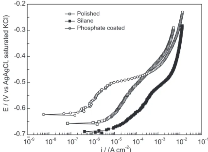
Figure 1 presents the anodic polarization curves for the polished Nd–Fe–B magnet and for samples protected with the two different coatings (silane or phosphate produced by 24 h immersion) after 1 h immersion in the PBS test solution. The curve for the sample protected with the BTSE layer presents a net depolarization when compared with the polished magnet, indicating that this coating is ineficient. On the other hand, a more polarized curve was obtained for the phosphated sample, indicating that this treatment improves the anticorrosion properties of the magnet.
EIS diagrams for a polished magnet after different immersion times in the PBS solution are shown in Figure 2; there is no relevant change during this period indicating that the system has attained its steady state. Two relaxation
phenomena are easily distinguished in the diagrams: at high frequencies a depressed loop is characterized, while at low frequencies a straight line indicates the existence of diffusion controlled processes.
Figure 2c presents the Nyquist diagram acquired after 1 h of immersion in the PBS solution. In this Figure is possible to verify that the high frequency capacitive loop
makes a 45o angle with the real axis. Normally this kind
of response is associated to diffusion controlled processes (Warburg impedance), however, due to the extremely high frequency where this loop occurs this response cannot be ascribed to such phenomenon, as solution diffusion of chemical species, either ions or molecules, is not an extremely fast process. During the sixties de Levie showed that the EIS response of a porous electrode is characterized by a Warburg-like behavior.15-17 Using a series of simplifying
hypothesis16 the author demonstrated that the impedance of
a porous electrode can be calculated as follows:18
(1)
Where R0 is the electrolyte resistance for a one-unit
length pore in Ω cm-1, Z
0 is the interfacial impedance for
a one-unit length pore in Ω cm and l is the length of each pore in cm. When l is large enough, which means that the
pores behave as if they were semi-ininitely long, the coth
term of the equation tends to 1, and the phase angle tends
to 45o independently of the frequency, like in the Warburg
system. In this situation the electrochemical reactions take place at the conductive pore walls, which surface area is superior to that of the lat surface area, and phase angles are divided by two when compared with the typical response of lat electrodes.
Regarding the second time constant, the diagram depicted in Figure 2c shows that the angle of the straight line with the real axis is around 22.5o. De Levie also showed
that the angle with the real axis of aWarburg impedance (diffusion controlled process) in a porous electrode with semi-ininite pore length is half that presented by a lat electrode.16 Therefore, the low frequency time constant
indicates that diffusion within the pores controls the low frequency impedance behavior. Taking into account these experimental results it is possible to say that the EIS response of the electrode in the whole frequency range is governed by a porous electrode behavior, in accordance with its production procedures: by powder metallurgy.
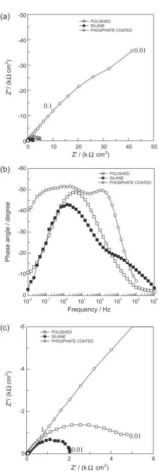
Figure 3 depicts the EIS diagrams, after 1 h immersion in the PBS solution, for a polished magnet and for samples protected with the phosphate coating and with the BTSE layer. In accordance with the results presented in Figure 1, the phosphate-coated sample presented a better EIS response than the polished magnet, while the EIS behavior of the BTSE-coated sample was the worst. Moreover, the impedance exhibited by the sample treated in the phosphating bath was more than one order of magnitude higher than that exhibited by the polished sample pointing towards very effective protective properties.
surface. The analysis of the low frequency (LF) response presented in these plots indicates that the presence of the phosphate layer delays the corrosion process, as it displaces this time constant to lower frequencies. On the other hand, the LF time constant of the silane-coated sample appears on the same frequency range as the polished one indicating the occurrence of phenomena with the same kinetics, conirming, therefore, the low eficiency of this treatment for the corrosion protection of the magnet.
The analysis of the Nyquist diagram for the phosphate-coated sample shows that in the high to middle frequency range (Figure 3c) a straight line, with approximately 45°, is formed between the diagram and the real axis. This response is likely linked to the porous nature of the Nd–Fe–B magnet, as already discussed for the bare sample. However in this case a mixed contribution of the thin phosphate layer and of the double layer charging must be responsible for this time constant as the phase angle associated with it is clearly widened when compared with the high frequency phase angle of the bare sample.
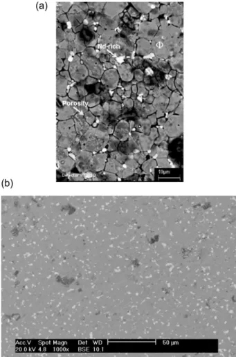
Figure 4 presents a SEM micrograph from the surface of a silane-coated magnet. The image shows that the BTSE ilm is not deposited homogeneously onto the magnet surface. Regions of heavy silane deposition, identiied by EDS analysis, co-exist with poorly coated ones. Particularly striking is the low afinity of the BTSE molecules for the Nd-rich regions, which present poor silane coverage even in areas characterized by heavy silane deposition. This uneven distribution of the silane on the magnet surface can explain the poor corrosion resistance exhibited by these particular samples, as galvanic cells can be formed between coated and uncoated regions. Moreover, few holes are also visible in the magnet surface, indicating that the acidic hydrolysis solution can attack the magnet surface.
Figure 3. Nyquist (a) and Bode phase angle (b) plots of polished, phosphate and silane (BTSE) coated Nd–Fe–B magnets; (c) zoomed image of (a) showing diagrams for polished and silane coated samples. Diagrams obtained at the OCP after 1 h immersion in PBS solution. Typical frequencies in Hz.
In Figure 5 a SEM image of the surface of a magnet coated with the phosphate conversion layer formed during 24 h of immersion is presented. The image does not show the formation of a layer above the electrode surface. However naked-eye observation of the sample surface after the deposition procedure clearly revealed the existence of interference colors, indicating the presence of a thin ilm on the electrode surface. Moreover, a detailed EDS survey performed at different spots of the coated sample revealed the presence of phosphorus, conirming the presence of the ilm.
The analysis of the image presented in Figure 5 reveals that the Nd-rich phase (white spots) is not corroded due to the immersion in the phosphating solution. The low corrosion resistance of the Nd–Fe–B magnets is normally ascribed to the electrochemical activity of this
phase,4 however during the phosphating treatment no
preferential attack could be observed in this phase. Indeed SEM observation of samples coated in the phosphate solution for shorter periods revealed that the matrix was more heavily attacked than the Nd–Fe–B phase. The solubility of the Nd phosphate is extremely low,13,19 we
propose that during the irst moments of immersion of the magnet in the phosphating solution a thin insoluble ilm of Nd phosphate would be formed above the Nd-rich phase protecting this phase from further attack. This was supported by EDS analyses above these phases, which gave higher Nd contents than in the polished sample allied with an intense phosphorus peak. Increasing the treatment time would make the ilm spread out all over the sample surface and within the pores improving its protective properties.
Figure 6 presents backscattered SEM images of the surface of an uncoated (Figure 6a) and of a phosphate-coated (Figure 6b) magnet after 4 h of immersion in the Figure 5. SEM image of the surface of a magnet coated with the phosphate conversion layer formed during 24 h of immersion.
PBS solution. The images show that while the uncoated sample was extremely etched during the test only localized regions were attacked when the sample was coated with the phosphate layer. Particularly striking in Figure 6b is the fact that the Nd-rich phase particles remain almost unattacked during the test, conirming the extra protection afforded to this phase by the phosphate layer.
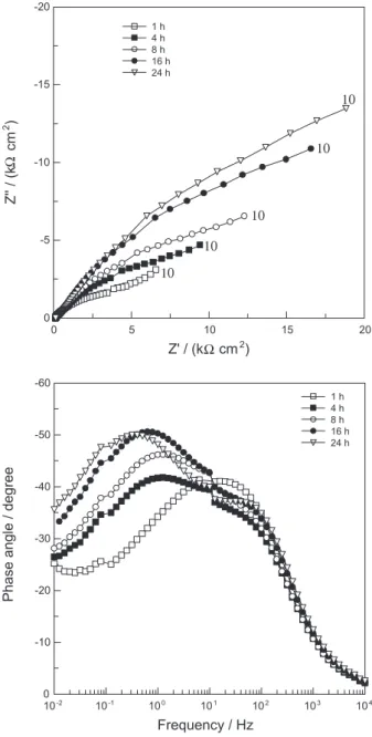
Figure 7. Evolution of the EIS response of a Nd–Fe–B magnet with immersion time in the phosphating bath. Typical frequencies in mHz.
is displaced to lower frequencies with immersion time, indicating increasing resistance to the corrosion process that leads to the formation of the phosphate ilm. On the other hand, in the high frequency region, a straight line making an angle of approximately 45° is veriied, pointing towards a porous electrode response; in addition the low frequency limit of this time constant is displaced to lower frequencies as the treatment time increases. This is indicative of the formation of the phosphate ilm on the pore walls. According to our interpretation, as the treatment time increases the pore walls are progressively coated with the phosphating layer. As the pores are more deeply coated, the corrosion process, which leads to the phosphate layer precipitation, takes place more deep within
the pores, explaining the displacement of the diffusion controlled process to lower frequencies. Differently from the uncoated sample immersed in the PBS solution an impedance response of porous electrode with semi-ininite pore length is not developed in the whole frequency range as the low frequency region of the impedance diagram, where a diffusion controlled process seems to take place, does not present a porous electrode response, which would be characterized by a 22.5° angle as depicted in Figure 2c. The impedance response also indicates that a diffusion controlled process controls the precipitation of the phosphate layer.
Conclusions
In the present work the electrochemical behavior of a powder metallurgy produced Nd–Fe–B magnet in PBS solution was investigated as well as the corrosion protection afforded by two different types of surface treatment: a phosphate and a silane (BTSE) layer.
The results of the EIS investigation have showed that, in the PBS solution, the Nd–Fe–B magnet behaves like a porous electrode with semi-ininite pore length, giving the
EIS response predicted by the de Levie theory,16 which is
consistent with the microstructure of a material produced by powder metallurgy.
The surface treatment of the Nd–Fe–B sintered magnet with the silane (BTSE) showed low afinity of the BTSE molecules for the Nd-rich regions, leading to poor silane coverage of this electrochemically active phase, even in the regions of heavy silane deposition. The uneven distribution of silane on the magnet surface explains the poor corrosion protection afforded by this coating, as galvanic cells can be formed between coated and uncoated regions.
The phosphating treatment produced a thin protective layer, not detectable by SEM observation but visible at naked-eye through interference colors. Unlike the silane treatment, this treatment does not attack the active Nd–Fe–B active phase. It is postulated that the phosphating solution provokes the precipitation of Nd phosphates mainly above the Nd rich phase, protecting it from further corrosion. This hypothesis was supported by SEM-EDS results which showed that after the phosphating treatment the Nd content on the Nd rich phase was increased when compared to the polished sample.
Acknowledgments
References
1. Sagawa, M.; Fujimura, S.; Togawa, N.; Yamamoto, H.; Matsuura, Y.; J. Appl. Phys. 1984, 55, 2083.
2. Campbell, P.; Permanent Magnet Materials and Their Application, Cambridge University Press: New York, 1994. 3. Harris, I. R.; Mater. Sci. Technol.1990, 6, 962.
4. El Aziz, A. M.; Kirchener, A.; Gutleisch, O.; Geber. A.; Shultz, L.; J. Alloys Compd. 2000, 311, 299.
5. Man, H. H.; Man, H. C.; Leunl, K.; J. Magn. Magn. Mater.
1996, 152, 47.
6. Blackwood, D. J.; Balakrisnan, B.; Huang Tan, C. K.; J. Magn. Magn. Mater.2001, 223, 103.
7. Cheng, F. T.; Man, H. C.; Chan, W. M.; Cheng, C. W.; Chan, W. O.; J. Appl. Phys.1999, 85, 5690.
8. Van Ooij, W. J.; Zhu, D. Q.; Corrosion2001, 57, 413. 9. Zhu, D. Q.; Van Ooij, D. J.; Eletrochim. Acta2004, 49, 1113. 10. Zucchi, F.; Grassi, V.; Frignani, A.; Monticelli, C. Trabanelli,
G.; Surf. Coat. Technol.2006, 200, 4136.
11. Novak, S.; Kobe, S.; Mcguiness, P.; Powder Technol.2004, 139, 140.
12. Hu, J.-M.; Liu, X.-L.; Zhang, J.-Q.; Cao, C.-N.; Prog. Org. Coat.2006, 55, 388.
13. Saliba-Silva, A. M.; Costa, I.; Key Eng. Mater.2001, 189-191, 363.
14. Saliba-Silva, A. M.; De Melo, H. G.; Baker, M. A.; Brown, A. M.; Costa, I.; Mater. Sci. Forum2003, 54, 416.
15. De Levie, R.; Electrochim. Acta1963,8, 751. 16. De Levie, R.; Electrochim. Acta 1964, 9, 1231.
17. De Levie, R. In Advances in Electrochemistry and Electrochemical Engineering; Vol. 6, Delahay, P., ed., New York, 1967, pp. 329-397.
18. Barcia, O. E.; D’Elia, E.; Frateur, I.; Mattos, O. R.; Pébère, N.; Tribollet, B.; Electrochim. Acta2002, 47, 2109.
19. Takeuchi, S. M. T.; Azambuja, D. S.; Saliba-Silva, A. M.; Costa, I.; Surf. Coat. Technol.2006, 24, 6826.
Submitted: May 5, 2010 Published online: September 23, 2010