Article
Printed in Brazil - ©2012 Sociedade Brasileira de Química0103 - 5053 $6.00+0.00A
*e-mail: [email protected], [email protected], [email protected], [email protected]
Electrochemical Reduction of the Mycotoxin Citrinin at Bare and
Modified with Multi-Walled Carbon Nanotubes Glassy Carbon Electrodes in a
Non-Aqueous Reaction Medium
Vanessa G. L. Zachetti,a Adrian M. Granero,a Sebastian N. Robledo,b María A. Zon,*,a Carlos A. DaRocha Rosac and Héctor Fernández*,a
aDepartamento de Química, Facultad de Ciencias Exactas, Físico-Químicas y Naturales,
Agencia Postal No. 3, 5800 Río Cuarto, Argentina
bDepartamento de Tecnología Química, Facultad de Ingeniería. Universidad Nacional de
Río Cuarto, Agencia Postal No. 3, 5800 Río Cuarto, Argentina
cNúcleo de Pesquisas Micológicas e Micotoxicológicas, Universidade Federal Rural do
Rio de Janeiro, 23890-000 Rio de Janeiro-RJ, Brazil
O mecanismo de redução eletroquímica de citrinina em acetonitrila mais (C4H9)4NClO4 0,1 mol L-1 tanto em eletrodo de carbono vítreo (GC) não modificado quanto em eletrodo GC
modificado com nanotubos de carbono de paredes múltiplas foi investigado por voltametria cíclica e eletrólise a potencial controlado. Os resultados obtidos permitiram inferir um mecanismo de eletroredução complexo com etapas químicas e eletroquímicas, acopladas à reação inicial de transferência de elétron. Citrinina apresentou pico catódico único que corresponde no mínimo a duas etapas de redução envolvendo um elétron e duas reações químicas homogêneas, segundo mecanismo de autoprotonação do tipo ECEC (transferência de elétron acoplada com aceitação de próton). As reações químicas se originam nas transferências de próton intermolecular do substrato para os seus produtos intermédios básicos de redução, caracterizando um mecanismo de autoprotonação. Análise cinética por procedimentos de simulação de resultados voltamétricos permitiu uma caracterização completa do mecanismo de redução heterogêneo de citrinina.
Electrochemical reduction mechanism of citrinin in acetonitrile plus 0.1 mol L-1 (C
4H9)4NClO4
at both bare and modified with multi-walled carbon nanotube glassy carbon (GC) electrodes was investigated by cyclic voltammetry and controlled potential electrolysis. Results allowed to infer a complex electroreduction mechanism with chemical and electrochemical steps coupled to the initial electron transfer reaction. Citrinin shows a single cathodic peak that corresponds at least to two electron reduction steps and two homogeneous chemical reactions, conforming to an ECEC (electron-transfer coupled with proton acceptance) self-protonation mechanism. The chemical reactions are originated in the intermolecular proton transfers from the substrate to its basic reduction intermediates, featuring a self-protonation mechanism. Kinetics analysis by simulation procedures of voltammetric results permitted a fully characterization of the mechanism of citrinin heterogeneous reduction.
Keywords: citrinin, mycotoxins, multi-walled carbon nanotubes, cyclic voltammetry, square
wave voltammetry
Introduction
Mycotoxins are a group of secondary metabolites produced by fungi of different species and have different structural characteristics.1 Some mycotoxins are carcinogenic,
others are immunosuppressive, vasoactive and others can cause central nervous system damage. Sometimes, the same mycotoxin can cause more than one type of toxic effect.1
Citrinin or (3R, 4S)-4,6-dihydro-8-hydroxi-3,4,5-trimethyl-6-oxo-3H-2-benzopyran-7-carboxylic acid (CITH, Figure 1) was first isolated from filamentous fungus Penicillium citrinum.2 It is also produced by other
CITH crystallizes in a disordered structure, with both
p-quinone and o-quinone tautomeric forms in a dynamic
equilibrium in the solid state (Figure 1).6
CITH was characterized as an antibiotic and its antifungal, bacteriostatic and antiprotozoal properties were verified. CITH is known as a hepato-nephrotoxin in a wide range of species.7 Studies carried out in vitro
have also demonstrated that CITH produced multiple effects on renal mitochondrial function and biosynthesis of macromolecules, which finally resulted in cell death.8
In addition, CITH frequently occurs together with another nephrotoxin-ochratoxin A in foodstuffs such as cereals, fruits, meat9 and cheese,10 and acts synergistically.11 CITH
enhances carcinogenicity induced by ochratoxin A.12 In our
previous work, the electrochemical behavior of ochratoxin A was studied.13 The presence of ochratoxin A, CITH and
aflatoxin B1 in rice samples collected from five provinces of central region in Vietnam was recently studied using high-performance liquid chromatography (HPLC) with fluorimetric detection.14 The level of contamination in rice
samples is affected by the season of the year, particularly the rainy season which proved to be the mayor risk factor for the presence of mycotoxins.
There is no specific legislation for CITH worldwide to date. The International Agency for Research on Cancer (IARC)15,16 classifies CITH in the group 3 because there is
little evidence of its toxicity in experiments conducted on animals and no evidence for human.
On the other hand, carbon nanotubes (CNT) have become the subject of intense investigation since their discovery.17 Such considerable interest reflects the unique
behavior of CNT, including their remarkable electrical, chemical, mechanical and structural properties. CNT can be single-walled carbon nanotubes (SWCNT) and multi-walled carbon nanotubes (MWCNT).18 The unique
properties of CNT make them extremely attractive for the task of chemical sensors, in general, and electrochemical detection, in particular. A review illustrated a growing number of applications of CNT in analytical chemistry.19
Another review covered the recent advances in the development of new designs of electrochemical sensors and
biosensors based on the use of modified electrode surfaces with CNT.20
No report related to the CITH electrochemical behavior in literature was found. CITH has both carbonyl group and phenolic species in its molecular structure (Figure 1), suggesting that CITH can be electrochemically reduced and/or oxidized, respectively. However, it is described herein the CITH electrochemical reduction at bare glassy carbon (GC) electrodes and modified MWCNT GC electrodes in acetonitrile (ACN) for the first time. Cyclic voltammetry (CV) and controlled potential electrolysis were the electrochemical techniques used. ACN plus 0.1 mol L-1 NaClO
4 was used as reaction medium for
performing measurements of controlled potential electrolysis. UV-Visible and infrared (IR) spectroscopies as well as thin layer chromatography (TLC) were used as non-electrochemical techniques in order to identify the reaction products obtained after performing the controlled potential electrolysis.
Experimental
Reagents
CITH (Sigma) was used as received. ACN, H2O,
acetone (Ac), toluene (Tol) and ethyl acetate (EA) were obtained from Sintorgan (HPLC grade). Triofluoroacetic acid (TFA) was from Sigma-Aldrich. ACN was dried over molecular sieves (3 Å) for 48 h prior to use and then used without further purification. TBAP (tetrabutylammonium perchlorate, Fluka, electrochemical grade) was dried in an oven under vacuum up to 60 °C for three days. Then, it was kept under vacuum before use. Stock solutions of CITH were prepared in ACN and kept at 4 °C in the dark. Working solutions were daily prepared by adding aliquots of stock solutions to the ACN plus 0.1 mol L-1 TBAP
reaction medium. The CITH bulk concentration (c*
CITH) was
varied from 2.0 × 10⁻⁷ to 3.0 × 10⁻³ mol L-1 for voltammetric
measurements. 8.0 × 10⁻⁴ mol L-1 c*
CITH was used to perform
controlled potential electrolysis measurements.
Apparatus and experimental measurements
CV and controlled potential electrolysis experiments were carried out with an AutoLab PGSTAT 12 potenciostat, controlled by GPES 4.9 electrochemical software from Eco-Chemie. In CV measurements, the scan rate (ν) was varied from 0.05 to 1 V s-1.
A two-compartment Pyrex cell was used to perform electrochemical measurements.21 The working electrode
was a bare GC disk (BAS, 3 mm diameter). It was polished
using 0.3 and then 0.05 µm wet alumina powder (from Fischer), copiously rinsed with H2O, and sonicated in
a water bath for 2 min. Then, it was electrochemically activated in aqueous 1 mol L-1 KOH (P.A., Merck) by
applying a potential step from 0 to 1.2 V for 5 min, according to a methodology described by Anjo et al.22
Finally, it was copiously rinsed with H2O and Ac, and
then dried under an air flow. For the MWCNT modified GC electrode, a dispersion of 1 mg of MWCNT (Sigma, outer diameter 30-50 nm, inner diameter 5-15 nm, length of 0.5-200 µm) + 1 mL H2O + 1% Nafion® (Aldrich)
was prepared and strongly sonicated in a water bath by 15 min. Then, 10 mL were dropped onto the GC electrode surface and allowed to dry under a lamp. The addition of Nafion® yielded more reproducible voltammetric signals.
The geometric area (A) of MWCNT modified GC electrode was calculated by chroamperometric experiments using 9.9 × 10⁻⁴ mol L-1 K
4[Fe(CN)6] + 0.5 mol L-1 KNO3
at 25 °C through the Cottrell plots,23 using a value of
7.6 × 10⁻⁶ cm2 s-1 for the K
4[Fe(CN)6] diffusion coefficient.24
An average value of 0.16 ± 0.01 cm2 for A was determined
from three replicated measurements performed with three different modified electrodes. The counter electrode was a large-area platinum foil (approximately 2 cm2). The
reference electrode was an aqueous saturated calomel electrode (SCE) fitted with a fine glass Luggin capillary containing a bridge solution identical to that containing the sample which was measured.
The controlled potential electrolysis cell was of the three compartment type.25 The working and counter electrode
compartments were separated by a fiber glass paper. The corresponding working electrode was a GC cylindrical bar, with a geometric area of 2.64 cm2.
The reduction peak of CITH (see below) was strongly affected by dissolved oxygen in the medium. To avoid this effect, the oxygen concentration was minimized by bubbling pure argon saturated with the blank solution through the CITH solution for about 20-25 min, until the classical oxygen reduction peak at about −1.0 V vs.
SCE disappeared.26 Then, an argon atmosphere was kept
above the solution in the cell throughout the experiment. The positive-feedback technique was employed in all experiments to compensate for solution resistance.
Cyclic voltammograms were convoluted, after background current subtraction, by applying the method proposed by Oldham.27 The fitting of the experimental cyclic
voltammograms was carried out by using BAS DigiSim®
software.
UV-Vis absorption spectra were recorded immediately after the preparation of the solutions using a Hewlett-Packard model 8452A spectrophotometer equipped
with temperature controller. Silica cells were of 1 cm path length. Absorbances at 236 and 333 nm were obtained from spectra recorded against the corresponding blanks. Absorption spectra at different c*
CITH in ACN
were recorded. Plots of A236ACNvs. c*CITH and A333ACNvs. c*CITH
were linear from 1.0 × 10⁻⁶ to 3.6 × 10⁻⁵ mol L-1. The
molar extinction coefficients at 236 and 333 nm in ACN were ε236ACN = (1.78 ± 0.04) × 104 mol-1 L cm-1 and
ε236ACN = (1.80 ± 0.04) × 104 mol-1 L cm-1, respectively. The
IR spectra were obtained in a Nicolet spectrophotometer, Impact 400 model. NMR (nuclear magnetic resonance) spectra were recorded with a Bruker 200 MHz NMR spectrophotometer. F254 fluorescent silica gel plates
(Merck) were used for performing TLC measurements. The temperature was 20.0 ± 0.2 °C.
Results and Discussion
Cyclic voltammetry
CITH cyclic voltammograms obtained at both bare and MWCNT modified GC electrodes, at a given scan rate (ν) are shown in Figure 2.
Reproducible voltammetric signals were obtained for both electrodes if the cathodic scan was started at an
E = +0.9 V with a waiting time of 60 s at that potential. Figure 2. Acyclic voltammogram of CITH at bare GC electrode (line A) and two consecutive cyclic voltammograms of CITH at MWCNT modified GC electrode (lines B and C). Reaction medium: ACN plus 0.1 mol L-1 TBAP,c*
A main reduction peak centered at about −0.98 V (peak I) at bare GC electrode and a very small pre-peak (peak II) in the potential range from −0.63 to −0.88 V were found during the first cathodic scan. No anodic complementary peak was observed when the direction of sweep potential was reversed, putting clearly in evidence that the CITH electroreduction mechanism is complex, with chemical(s) and or electrochemical reaction(s) coupled to the initial charge transfer. The peak at E = −0.98 V can be assigned to the electroreduction of the carbonyl group present in CITH chemical structure (marked with an asterisk in Figure 1). The intensity of the small pre-peak was dependent of the electrode material, the scan rate and the c*
CITH used. The pre-peak was better defined at modified
GC electrodes at low scan rates and high c*
CITH (see below).
Moreover, two very small anodic peaks apparently of surface nature in the potential range from ca. 0.22 to 0.75 V
were found during the first reverse anodic scan, being better defined in the modified electrode than in the bare GC electrode (lines B and C in Figure 2). The nature of these two small anodic peaks is not yet known.
Cyclic voltammograms of CITH recorded at MWCNT modified GC electrodes showed a significant increase in the cathodic peak current (Ip,c), about 2.2 times higher
than at the bare GC electrode. On the other hand, the catalytic effect found at modified GC electrodes was insignificant, being the cathodic peak potential (Ep,c) only
shifted at 0.02 V lesser cathodic than that found at bare GC electrodes (compare lines B and C with line A in Figure 2). Voltammetric signals showed very good reproducibility and repeatability. Thus, percent relative standard deviations (RSD) of 0.32 and 4.20% were found for the Ep,c and Ip,c,
respectively, from cyclic voltammograms recorded with five different modified electrodes at a given scan rate, showing a good reproducibility. Cyclic voltammograms recorded with the same modified electrode at a given scan rate showed a high repeatability (lines B and C in Figure 2).
Plots of Ip,cvs. ν1/2 were linear (Figure 3), showing
that the electrode process is diffusion controlled.23
Plots of Ep,c vs. log ν (for five different c*
CITH) and
Ep,c vs. log c*CITHwere also linear, with average slopes of
–0.032 ± 0.002 V decade-1 and 0.031 ± 0.002 V decade-1,
respectively. Clearly, the variation of Ep,c – log c*CITH is
indicative of a second order character for the first coupled chemical reaction.28
Diffusion coefficient of CITH was calculated from convoluted cyclic voltammograms after subtracting the background currents (Figure 4).
Convoluted currents (Icon) did not return to zero after
the cyclic scan was completed. This behavior indicates that the product of the initial reduction step is consumed
by a homogeneous chemical reaction coupled to the initial electron transfer reaction in agreement with results of cyclic voltammetry.23,29 A tentative diffusion coefficient
was calculated considering the convolution model for ECE (electron transfer) reaction mechanism.29 Thus, plots
of Evs. log [(IL,con - Icon)/I] obtained in the scan rate range
from 0.025 to 0.100 V s-1 were linear, with an average
slope of 0.0564 ± 0.0004 V decade-1 (linear correlation
coefficient, r = 0.9995), where IL,con is the convoluted
limiting current and I the experimental current. By inserting
the average slope obtained in the expression for IL,con, as it
is shown in the following expression:29
Figure 3. Dependence of the cathodic peak current (Ip,c) with ν1/2 at different
c*
CITH in ACN plus 0.1 mol L-1 TBAP at MWCNT modified GC electrodes:
(line A) c*
CITH = 2.4 × 10⁻⁴ mol L-1 (slope = (2.9 ± 0.1) × 10-5 A V-1 s, r = 0.9941,
(line B) c*
CITH= 3.4 × 10⁻⁴ mol L-1 (slope = (4.6 ± 0.1) × 10-5 A V-1 s, r = 0.9957)
and (line C) c*
CITH= 6.8 × 10⁻⁴ mol L-1 (slope = (9.1 ± 0.2) × 10-5 A V-1 s,
r = 0.9980).
Figure 4. Cyclic convoluted and cyclic voltammograms of CITH in ACN plus 0.1 mol L-1 TBAP at MWCNT modified GC electrodes,
c*
IL,con = 2n F A DCITH1/2 c*
CITH (1)
where A is the electrode area, DCITH is the CITH diffusion
coefficient and the other terms have their usual meaning, an average value of (6.77 ± 0.07) × 10-6 cm2 s-1 for D
CITH
was calculated in ACN plus 0.1 mol L-1 TBAP.
Convoluted cyclic voltammograms were obtained at three c*
CITH with both bare (A = 0.071 cm2) and MWCNT
modified GC (A = 0.16 cm2) electrodes. As it will be shown
below, the calculated DCITH agrees quite well with the one
obtained by fitting of experimental data with simulated voltammograms for an ECEC (electron-transfer coupled with proton acceptance) reaction mechanism.
The dependence of the non-dimensional experimental current function Ψ with ν1/2 for three different c*
CITH and
eight scan rates (from 0.025 to 0.2 V s-1) is shown in
Figure 5.23,30
As can be observed, Ψ for the CITH electroreduction peak decreased as the scan rate increased. Ψ also
reached higher values at lower c*
CITH for a given scan
rate. The behavior of Ψ with both scan rate and c* CITH
is in agreement with results previously obtained by us related to the electroreduction of progesterone.30
Moreover, these results obtained on the voltammetric time scale (seconds to milliseconds in the present study) are fully consistent with a second-order chemical reaction coupled to the initial electron transfer reaction in agreement with the Ep,c – log ν = –0.032 V decade-1 and
Ep,c – log c*
CITH= 0.031 V decade-1, shown above.23,28,30,31
Controlled potential electrolysis
Controlled potential electrolysis was carried out at
E = −1.25 V for 60 min. Cyclic voltammograms recorded during the electrolysis showed a pronounced diminution in the CITH reduction peak current (peak I) and the increase of a wide pre-peak (peak II) in the potential range from about −0.4 to −0.9 V. Besides, a new oxidation peak of surface nature with a peak potential at about 0.8 V (peak III) increased as the electrolysis time increased (Figure 6). The surface nature of the oxidation peak (peak III) obtained after performing controlled potential electrolysis can be inferred taking into account the shape of the corresponding oxidation peak. This oxidation peak can be assigned to the oxidation of phenolic species13 present in the reaction
product obtained from the controlled potential electrolysis of CITH, as discussed later.
In addition, a small anodic peak (peak IV) of surface nature was observed in the cyclic voltammogram recorded
Figure 5. Dependence of the non-dimensional experimental current function (Ψ) with ν1/2 at different c*
CITHin ACN plus 0.1 mol L-1 TBAP
at MWCNT modified GC electrodes, (a) c*
CITH = 2.0 × 10⁻³ mol L-1, and
(b) (line A) c*
CITH = 6.8 × 10⁻⁴ mol L-1 and (line B) c*CITH = 2.0 × 10⁻⁴ mol L-1.
Figure 6. Cyclic voltammograms of CITH in ACN plus 0.1 mol L-1 NaClO 4
at a bare GC electrode at the following different controlled potential electrolysis times: (line A) 0, (line B) 15, (line C) 30 and (line D) 60 min,
ν = 0.05 V s-1, c*
at the end of the electrolysis. This peak could be assigned as the complementary anodic peak of the cathodic peak width (peak II).
The curve Ivs. t at relatively short times (about 100 s)
was used to extract the electron number exchanged in the reduction process.23 Thus, the combination of the following
equations for the current and the charge (Q) was used to determine the number of electrons exchanged in the electrode process:
I(t) = I(0) exp(−pt) (2)
and
Q(t) = Q(0)[1 - exp(−pt)] (3)
where I(0) is the current at t = 0, Q(0) = nFV c*CIH and
p = moA/V, being mo the mass transfer coefficient and
V the solution volume.21,30 For short times, Q(t) can be
expressed as:30
ln Q(t) = ln Q(0) + ln p + ln t (4)
Then, n is calculated through the combination of the intercept and the slope of linear plots of ln Q vs. ln t and
ln I(t) vs. t, respectively. An average value of n = 0.69 ± 0.03
was obtained from three replicated measurements. UV-Vis absorption spectra recorded at different times during the controlled potential electrolysis showed a diminution in band intensities at 236 and 333 nm as the electrolysis time increased. Finally, two new bands centered at 243 and 312 nm were observed for the electrolysis product. These results allow inferring that the number of conjugated double bonds in the electrolysis product would be similar to those present in CITH chemical structure.
Mechanism of electrochemical reduction of CITH: digital simulation
On the base of different diagnostic criteria discussed in literature for cyclic voltammograms28,29,31 and simulation
though DigiSim® software, different theoretical reaction
mechanisms involving heterogeneous and homogeneous chemical reactions28-32 were used to perform the fit of CITH
experimental cyclic voltammograms, i.e., ECE, DIM2 (radical-substrate coupling), ECEC self-protonation, etc. The best fitting was obtained when the following theoretical mechanism was used to fit experimental voltammograms (Figure 7):
CITH + e– CITH– • (5)
CITH– • + CITH CITH•
2 + CIT– (6)
CITH•
2+ e– CITH–2 (7)
CITH–
2 + CITH CITH3 + CIT– (8)
———————————————
3 CITH + 2 e– CITH
3 + 2 CIT– (9)
which involve the exchange of 0.67 electrons per mole of
electrolyzed substance in the time scale of voltammetric measurements (short times). The reduction of several organic compounds has been interpreted as involving a proton transfer reaction between the initial anion radical and the starting molecule. They are called as “father-son” reaction (starting molecule-anion radical).33 Therefore, the radical
anion generated in the initial electron transfer reaction (equation 5, characterized by a formal potential, Efo(1), a
formal rate constant kfo(1) and a cathodic transfer coefficient,
α(1)) is then protonated by the starting molecule (equation 6, characterized by an apparent equilibrium constant, Ke(1) and
a homogeneous forward rate constant, kf(1)). The radical
generated in equation 6 is then reduced at the electrode surface at a potential slightly lower that the own substrate (equation 7, kfo(2) and α(2)) giving the corresponding anion,
which is again protonated by the starting molecule to give the final product (equation 8, with Ke(2) and kf(2)).
Simulation was performed by using the DigiSim®
software. The thermodynamic and kinetics parameters obtained from the best fitting were: Efo(1) = −1.09 V,
kfo(1) = 10 cm s-1, α(1) = 0.5, Ke(1) = 6.1 × 10¹¹ mol-1 L,
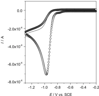
Figure 7. Experimental (-) and fitted (o) cyclic voltammograms of CITH in ACN plus 0.1 mol L-1 TBAP at a MWCNT modified GC electrode,
c*
CITH = 2.0 × 10⁻⁴ mol L-1, ν = 0.025 V s-1. The theoretical mechanism used
kf(1) = 9.4 × 10⁷ mol-1 L s-1, Efo(2) = −0.86 V,kfo(2) = 10 cm s-1,
α(2) = 0.5, Ke(2) = 6.5 × 10⁸ and kf(2) = 6.5 × 10⁷ s-1.
Values of kfo and α were fixed considering a reversible
behavior and were kept constant for all simulations, while other thermodynamic (K) and kinetics (kf) parameters were
calculated from the best fitting.
Based on these results, it was generated the theoretical cyclic voltammograms for different scan rate and substrate bulk concentration (c*) using the mechanism indicated in equations 5-8. From these theoretical voltammograms, it was analyzed the dependence of Ep,c with both scan rate and c*. Therefore, it was
found that ∂Ep,c/∂logv = −0.028 ± 0.001 V decade-1 and
∂Ep,c/∂log c* = 0.030 ± 0.001 V decade-1, which are in a
good agreement with the experimental values found for these dependences.
Therefore, the reaction mechanism proposed for the electroreduction of CITH at short times is an ECEC type, where E and C represent electrochemical and chemical steps, respectively.
These results are in good agreement with those obtained from controlled potential electrolysis, and the behavior of Ψvs.ν1/2 at different c*
CITH (Figure 5), which put in evidence
that the homogeneous chemical reaction coupled to the initial electron transfer would be of the second order.
Identification of CITH electroreduction product(s)
The IR spectrum of a CITH solution is shown in Figure S1 (Suplementary Information (SI) section). The band at 1635 cm-1 (Figure S1a) can be assigned to the
C=O stretching absorption band of the ketone and/or carboxylic acid groups present in the CITH molecular structure (Figure 1).
It is well known that the C=O group in ketones, aldehydes, carboxylic acids, anhydrides, amides, lactones and lactams shows a strong stretching band in the region between 1540 and 1870 cm-1.34,35 Besides, the bands observed at
3544 and 3632 cm-1 (Figure S1b) can be assigned to O-H
stretching vibrations of carboxylic and phenolic groups, respectively. The stretching IR absorption bands for O-H are theoretically predicted in the region from 2500 to 3000 cm-1 and from 3590 to 3650 cm-1 for carboxylic acids and
phenols, respectively.35 The two intramolecular hydrogen
bonds present in the CITH chemical structure (Figure 1)6
might explain the apparition of O-H stretching bands at a slightly greater energy.
Immediately after performing controlled potential electrolysis measurements on CITH solutions, the reaction product was separated from the solvent by evaporation. Then, the reaction product was dissolved in water plus
dichloromethane (1:1) mixture and transferred to a separator funnel in order to eliminate the inorganic salt (NaClO4).
The aqueous phase was discarded. Then, the organic solvent was eliminated by evaporation and, finally, the product(s) was(were) dissolved in ACN and the IR spectrum was recorded (Figure S2 in the SI section). As can be observed, the intensity of the reaction product band centered at 1633 cm-1 (Figure S2a) is lower than that obtained for
CITH solution before performing the controlled potential electrolysis (compare Figures S1a and S2a). In addition, the intensities of the reaction product bands centered at 3544 and 3632 cm-1 (Figure S2b) are higher than those for
CITH solution before performing the controlled potential electrolysis (compare Figures S1b and S2b). However, no significant change in the absorption band positions was established (compare Figures S1 and S2).
These results might suggest that a dimeric structure would be the product obtained after performing the controlled potential electrolysis. CITH2– (equation 7) is
a nucleophilic anion or carbanion (Figure 8a) which can react with α, β-unsaturated ketones to give the conjugated addition product, rather than the direct addition product.36
Therefore, the CITH2– carbanion (equation 7) may
react with another CITH molecule to give the conjugated addition product following the well-known Michael type reaction.36 It is known that CITH undergoes a Michael-type
nucleophilic addition reaction in methanol or methanol plus methylene chloride mixtures.6 Thus, it is propose the
following reaction mechanism at long times:
Figure 8. Chemical structures of (a) the carbanion CITH2- (equation 7) and
CITH + e– CITH– • (10)
CITH– • + CITH CITH•
2 + CIT– (11)
CITH•
2+ e– CITH–2 (12)
CITH–
2 + CITH (CITH)2H– (13)
(CITH)2H– + CITH (CITH)2H2 + CIT– (14)
—————————————————— 4 CITH + 2 e– (CITH)
2H2 + 2 CIT– (15)
where 0.5 electrons are consumed by mole of electrolyzed reagent.
The exchanged electron number determined experimentally at long times was n = 0.51 ± 0.01 for three replicated measurements. The chemical structure of the dimeric product (CITH)2H2 is shown in Figure 8b. The
presence of the same functional groups in the dimeric product and in the chemical structure of CITH explains that there are no changes in the positions of the absorption bands of IR spectra. On the other hand, the decrease in the intensity of the stretching band of C=O group in the electrolysis reaction product compared to the corresponding absorption band in the solution of CITH can be explained considering that the C=O group is involved in the Michael reaction. Moreover, the increase in the intensity of stretching bands of −OH group in the dimeric product compared to the solution of CITH may be explained considering that there are a greater number of acids and phenolic groups in the dimeric compound.
On the other hand, 3 mL of the electrolysis product dissolved in ACN were spotted on TLC silica gel plates next to a CITH standard sample as control. A Tol:EA:TFA (6:3:1) mixture was used as the developing solvent following a procedure previously described.37 Both pure CITH and
electrolysis product were detected as yellow-green spots under 254 nm light. The electrolysis product showed only one spot. Rf values were 0.75 for both spots. These results
would be in good agreement with those obtained from IR spectrum, indicating that the structures of CITH and final electrolysis product have identical functional groups and a very similar polarity.
Conclusions
In this work, it was demonstrated that citrinin mycotoxin is electrochemically reduced at both bare and MWCNT modified GC electrodes in ACN plus 0.1 mol L-1 TBAP.
Results obtained by cyclic voltammetry showed that citrinin electrochemical reduction is complex, with chemical and electrochemical reactions coupled to the initial electron transfer reaction, conforming an ECEC self-protonation mechanism. Thermodynamic and kinetics parameters were determined from digital simulation of cyclic
voltammograms. It is proposed that the reaction product at long times involves a Michael reaction, with the formation of a dimeric species.
Supplementary Information
Supplementary data (IR spectra of CITH before and after performing controlled potential electrolysis) are available free of charge at http://jbcs.sbq.org.br as a PDF file.
Acknowledgements
V. G. L. Zachetti thanks the Doctoral fellowship from Consejo Nacional de Investigaciones Científicas y Técnicas (CONICET) and Agencia Córdoba Ciencia, Argentina. Also, V. G. L. Zachetti thanks to CITED Program No. 109AC0371 for financial support for travelling to Universidade Federal Rural do Rio de Janeiro, Rio de Janeiro, Brazil. We wish to thank to the Secretaría de Ciencia y Técnica (SECyT) from the Universidad Nacional de Río Cuarto and CONICET for financial supports. We also thank to the Referee for his valuable suggestions.
References
1. Bräse, S.; Encinas, A.; Keck, J.; Nising, C. F.; Chem. Rev. 2009,
109, 3903.
2. Phillips, R. D.; Wallace Hayes, A.; Berndt, W. O.;
J. Chromatogr., A1980, 190, 419.
3. Ei-Banna, A. A.; Pitt, J. I.; Leistner, L.; Syst. Appl. Microbiol.
1978, 10, 42.
4. Pohland, A. E; Dowell, V. R.; Richards, J. L. In Microbial Toxins in Foods and Feed; Kurata, H., ed.; Plenum Press: New York, USA, 1990.
5. Blanc, P. J.; Laussac, J. P.; Le, J. B.; Le, B. P.; Loret, M. O.; Pareilleux, A.; Prome, D.; Prome, J. C.; Santerre, A. L.; Goma, G.;
Int. J. Food Microbiol.1995, 27, 201.
6. Xu, B.; Jia, X.; Gu, L.; Sung, C.; Food Control2006, 17, 271.
7. Berndt, W. O. In Ochratoxin-Citrinin as Nefhrotoxins, 3th ed.;
Llewellyn, G. G.; O’Rear, P. C., eds.; Plenum Press: New York, USA, 1990.
8. Chagas, G. M.; Oliviera, M. B. M.; Campello, A. P.; Kluppel, M. L. W.; J. Appl. Toxicol. 1995, 15, 91.
9. Nishijima, M. In Toxicogenic Fungi; Kurata. H; Ueno. Y, eds.;
Elsevier: Amsterdam, The Netherlands, 1984.
10. Vazquez, B. I.; Fente, C.; Franco, C.; Cepeda, A.; Prognon, P; Mahuzier, G; J. Chromatogr., A 1996, 727, 185.
12. Kanizawa, M.; Dev.Food Sci. 1984, 7, 245.
13. Ramírez, E. A.; Zon, M. A.; Jara Ulloa, P. A.; Squella, J. A.; Vergara, L. N.; Fernández, H.; Electrochim. Acta2009, 55, 771. 14. Nguyen, M. T.; Tozlovanu, M.; Tran, T. L.; Pfohl-Leszkowicz, A.;
Food Chem.2007, 105, 42.
15. International Agency for Research on Cancer (IARC), 2006, available in: http://monographs.iarc.fr/ENG/Classification/ index.php accessed in March 2012.
16. Arévalo, F. J.; Granero, A. M.; Fernández, H.; Raba, J.; Zon, M. A.; Talanta2011, 83, 966.
17. Iijima, S.; Nature1991, 354, 56.
18. Baughman, R. H.; Zakhidov, A; Heer, W. A.; Science2002, 297,
787.
19. Trojanowicz, M.; TrAC, Trends Anal. Chem.2006, 25, 480.
20. Aguí, L.; Yáñez-Sedeño, P.; Pingarrón, J. M.; Anal. Chim. Acta
2008, 622, 11.
21. Fernández, H.; Zon, M. A.; J. Electroanal. Chem.1992, 332, 237.
22. Anjo, D. M.; Kahr, M.; Khodabakhsh, M. M.; Nowinski, S.; Wanger, M.; Anal. Chem.1989, 61, 2603.
23. Bard, A. J.; Faulkner, L. R.; Electrochemical Methods: Fundamentals and Applications, 2nd ed.; Marcel Dekker: New
York, 2001.
24. Zon, M. A.; Moressi, M. B.; Sereno, L. E.; Fernández, H.; Bol. Soc. Chil. Quím.1994, 39, 139.
25. Arévalo, A. H.; Fernández, H.; Silber, J. J.; Sereno, L. E.;
Electrochim. Acta 35 1990, 35, 741.
26. Izutsu, K.; Electrochemisry in Nonaqueous Solutions; Wiley-VCH: New York, 2002.
27. Oldham, K. B.; Anal. Chem.1986, 58, 2296.
28. Andrieux, C. P.; Nadjo, L.; Saveant, J. M.; J. Electroanal. Chem.
1973, 42, 223.
29. Arévalo, F. J.; Molina, P. G.; Zon, M. A.; Fernández, H.; J. Electroanal. Chem.2008, 619-620, 46.
30. Andrieux, C. P.; Nadjo, L.; Saveant, J. M.; J. Electroanal. Chem.
1970, 26, 147.
31. Imbeaux, J. C.; Saveant, J. M.; J. Electroanal. Chem.1973, 44,
169.
32. Parker, V. D.; Acta Chem. Scand.1998, 52, 154.
33. Amatore, C.; Capobianco, G.; Farnia, G.; Sandona, G.; Saveant, J. M.; Severin, M. G.; Vianello, E.; J. Am. Chem. Soc.1985,
107, 1815; Costentin, C.; Robert, M.; Savéant, J.-M.; Chem.
Rev. 2010, 110, PR1.
34. McMurry, J.; Organic Chemistry, 2nd ed.; Brooks/Cole
Publishing Company: USA, 1988.
35. Silverstein, R. M.; Bassler, G. C.; Morrill, T. C.; Spectroscopy Identification of Organic Compounds, 4th ed.; J. Willey & Sons:
New York, 1981.
36. Solomons T. W.; Fundamentals of Organic Chemistry; J. Willey
& Sons: New York, 1982.
37. Odhav, B.; Naicker, V; Food Addit. Contam.2002, 19, 55.
Submitted: September 7, 2011
Supplementary Information
Printed in Brazil - ©2012 Sociedade Brasileira de Química0103 - 5053 $6.00+0.00S
I
*e-mail: [email protected], [email protected], [email protected], [email protected]
Electrochemical Reduction of the Mycotoxin Citrinin at Bare and
Modified with Multi-Walled Carbon Nanotubes Glassy Carbon Electrodes in a
Non-Aqueous Reaction Medium
Vanessa G. L. Zachetti,a Adrian M. Granero,a Sebastian N. Robledo,b María A. Zon,*,a Carlos A. DaRocha Rosac and Héctor Fernández*,a
aDepartamento de Química, Facultad de Ciencias Exactas, Físico-Químicas y Naturales,
Agencia Postal No. 3, 5800 Río Cuarto, Argentina
bDepartamento de Tecnología Química, Facultad de Ingeniería. Universidad Nacional de
Río Cuarto, Agencia Postal No. 3, 5800 Río Cuarto, Argentina
cNúcleo de Pesquisas Micológicas e Micotoxicológicas, Universidade Federal Rural do
Rio de Janeiro, 23890-000 Rio de Janeiro-RJ, Brazil
Figure S1. IR spectrum of CITH before performing controlled potential electrolysis,c*
CITH= 8.0 × 10⁻⁴ mol L-1.