Article
Printed in Brazil - ©2012 Sociedade Brasileira de Química0103 - 5053 $6.00+0.00
A
*e-mail: [email protected]
Effect of Calcium Phosphate Coating on Polyamide Substrate for
Biomaterial Applications
Lucimara C. Bandeira,a Kátia J. Ciuffi,a Paulo S. Calefi,a Eduardo J. Nassar,*,a
Jorge V. L. Silva,b Marcelo Oliveira,b Izaque A. Maia,b Isabel M. Salvadoc and
Maria Helena V. Fernandesc
aUniversidade de Franca, Av. Dr. Armando Salles Oliveira, No. 201, 14404-600 Franca-SP, Brazil
bCentro da Tecnologia da Informação Renato Archer (CTI),
Rod. Dom Pedro I, km 143.6, 13069-901 Campinas-SP, Brazil
cDepartamento de Engenharia Cerâmica e do Vidro, Universidade de Aveiro,
CICECO, 3810, Aveiro, Portugal
Um novo material a base de poliamida revestida com fosfato de cálcio foi desenvolvido visando potencial aplicação como biomaterial. O revestimento foi obtido pelo método sol-gel e o fosfato de cálcio foi obtido após contato com solução de fluído corpóreo. A poliamida revestida (antes e depois de contado com fluído corpóreo) foi caracterizada através de análises termogravimétrica e térmica diferencial (TGA/DTA), calorimetria diferencial de varredura (DSC), microscopia eletrônica de varredura (SEM) e espectrometria de reflexão total atenuada no infravermelho com transformada de Fourier (ATR-FTIR). As caracterizações revelaram a formação de fosfato de cálcio com uma espessura menor que 3 µm, o que proporcionou um aumento no ponto de fusão além de melhorar a estabilidade térmica da poliamida. Após contato com o fluído corpóreo, as interações entre o revestimento e o substrato se mantiveram, e houve formação de fosfatos cristalinos e amorfos na superfície de poliamida.
A new type of material from polyamide coated with calcium phosphate was developed aiming to have potential application as biomaterial. Coating was obtained by the sol-gel method and calcium phosphate was obtained after contact with body fluid solution. The coated polyamide (before and after contact with body fluid solution) was characterized by thermogravimetric and differential thermal (TGA/DTA) analyses, differential scanning calorimetry (DSC), scanning electron microscopy (SEM) and attenuated total reflectance Fourier transform infrared spectroscopy (ATR-FTIR). These characterizations revealed that the calcium phosphate coating has a thickness of less than 3 µm, which resulted in an increase in the melting point and improved the thermal stability of polyamide. After contact with body fluid, the interactions between the coating and the substrate remained, and there was formation of crystalline and amorphous phosphates on polyamide surface.
Keywords: sol-gel, dip-coating, rapid prototyping, polyamide coated with calcium phosphate, biomaterial
Introduction
The design of novel, inexpensive, biocompatible materials is crucial to the improvement of the living conditions and welfare of the population in view of the
increasing number of people who need implants.1 In this
sense, it is necessary to have processes for the biomaterial
production that are affordable, fast and simple to carry out. In this context, some researchers have studied the use of polyamide (PA) for the preparation of biocompatible implants because of its excellent mechanical properties, low cost and easy handling. In fact, PA has already been proven to possess good biocompatibility with various human cells and tissues, probably because of its similarity with the collagen protein in terms of chemical structure and
be further improved via synthesis of hybrid materials containing hydroxyapatite (HA), which leads to good
cellular responses in vitro.3-5
Additive Manufacturing (from American Society for Testing and Materials, ASTM) is a set of technologies employed in the structuring of 3D parts achieved through a computer program. It has been widely used in various areas and for many different applications, with emphasis on the ability of these technologies to recreate various types of human tissues in deinking material by means of magnetic resonance X-ray imaging and by the use of a specialized computer program. Additionally, additive manufacturing has been extensively investigated as a potential tool for the fabrication of bone scaffolds and customized implants with desired and controlled
internal architecture.5 A very simple and effective PA
structure forming 3D objects can be obtained by additive
manufacturing using selective laser sintering (SLS).6
This SLS technique enables the rapid and reproducible manufacture of products with precise dimensions and complex structure thanks to the action of lasers that increase the temperature of the material in the powder form to its melting point, at this temperature, the particles
coalesce and form layers in two dimensions.7,8
The sol-gel methodology is widely employed in the production of glasses, oxides, thin films, and coatings, among others. This process is based on the hydrolysis and condensation of metal alkoxide or semi-metallic precursors, leading to the formation of an inorganic polymer or
hybrid material.9-12 Moreover, it is well-established in the
literature that it is possible to create active sol-gel
silica-based biomaterials for use in bone tissue regeneration.13-17
It has been reported that Si−OH groups18,19 induce the
formation of apatite in a biomimetic solution.20 Indeed,
different substrates with distinct geometries can be coated by means of the sol-gel process at room temperature and pressure using the dip-coating technique, which consists in
immersing the material directly into the prepared sols.21,22
In this context, our proposal is to coat PA prepared by additive manufacturing with calcium phosphate by means of the sol-gel technique, which is a fast and simple chemical process that does not require the use of heat treatment or high pressure. The sols used for coating were prepared with and without phosphate ion, and physical and bioactive properties of composite material were available. The bioactive assays were preformed in simulated body fluid (SBF) solution. The materials were characterized by scanning electron microscopy (SEM), thermogravimetric and differential thermal (TGA/DTA) analyses, differential scanning calorimetry (DSC) and Fourier transform infrared spectroscopy (FTIR).
Experimental
Substrates
The substrates used in this work were rectangular slides with dimensions of 75 × 25 × 1 mm. They were built in an
SLS equipment (50 W RF-excited CO2 laser, wavelength
of 10.6 µm and laser spot of 450 µm.) utilizing DuraForm PA as raw material. The latter is a polyamide 12 (PA 12) powder that contains additives. Both the equipment HiQ Sinterstation model and the powder were supplied by the 3D System Co. (U. K.). The processing parameters were:
layer thickness of 100 µm, laser scan speed of 55 mm s-1,
laser power of 12-13 W, part bed temperature of 175 oC and
roller speed of 177 mm s-1.
Sol preparation
The sol was prepared by adding 4 mL
tetraethyl-orthosilicate (TEOS), as Si−OH source, 1.0 mL calcium
nitrate ethanolic solution (8.0 mol L-1), and 0.13 mL
phosphoric acid 85% to 32.0 mL ethanol, under magnetic stirring. After 30 min of agitation, 2.4 mL ammonia (as catalyst) ethanolic solution was added to the reaction mixture. For comparison purposes, a sol without phosphate was also prepared. The Ca/P and Ca/Si molar ratios were 1:0.1 and 1:2, respectively.
Polyamide coating
After 2 h of agitation, the sol was deposited onto PA
by dip-coating, as described in literature.23 The substrates
remained in the sols for 20 min, followed by drying at 50° C for 1 day.
Simulated body fluid (SBF)
The SBF solution was prepared in aqueous medium
by the addition of the reagents NaCl, NaHCO3, KCl,
Na2HPO4.2H2O, MgCl2.6H2O, HCl, CaCl2.H2O, NaSO4 and
NH2C(CH2OH) under stirring. The final pH was 7.43.24
Characterizations
Scanning electron microscopy (SEM) of the materials was performed in a digital scanning electron microscope JEOL JSM T330A. The samples were coated with a thin gold layer using a sputtering method.
at a heating rate of 20 ºC min-1 and under air flow of
100 mL min-1.
The FTIR absorption spectra were obtained with a Mattson 7000 spectrophotometer with Fourier transform, using the reflectance technique.
Results and Discussion
Scanning electron microscopy (SEM)
SEM images of the samples before the in vitro test
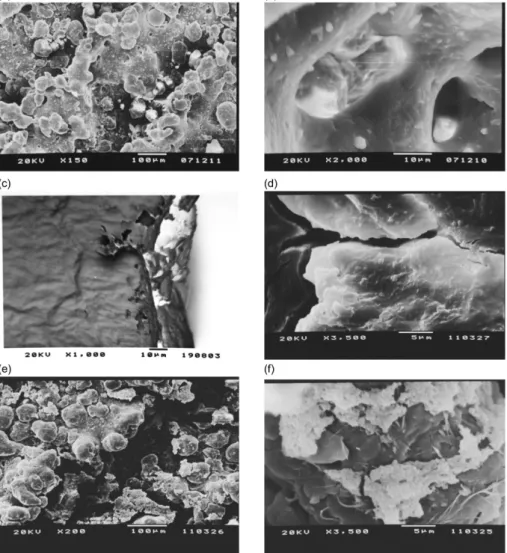
Figures 1a and 1b display the SEM of the PA substrate before coating. The PA surface is not homogeneous, in fact, several particles formed after sintering with laser, and there are pores due to the laser wavelength employed during SLS. Figure 1c corresponds to the micrograph that evaluates the thickness of PA coated with the sol prepared with phosphate (NcP), which has a very small thickness. This is ascribed to the use of the dip-coating technique, which is known to yield films with thickness lower than 1 µm. Figure 1d
shows the NcP surface, where a homogeneous film with cracks can be noted probably due to the rate of solvent drying. Figures 1e and 1f depict the SEM micrographs of PA coated with the sol prepared without phosphate (NsP). In this case, the film is not homogeneous and consists of agglomerates, contrary to what was observed in the case of NcP. This can be attributed to the fact that the phosphate ion can promote formation of an inorganic polymer in the NcP. This desirable feature enables total coating of the PA substrate and allows its application in biomaterials.
Several works have used polyamide and hydroxyapatite
to prepare a biocomposite.25,26 In these cases, the authors
obtained a porous structure, but the preparation of the materials did not yield a coating. Other works have reported the production of films with calcium chloride and aromatic
polyamide containing –COOH19 or polyamide containing
sulfonic groups,20 and the influence of Si
−OH groups on
the formation of hydroxyapatite was investigated. When these works are compared with ours, the difference is that, in the present work, the sol-gel methodology was used to
coat the polyamide piece obtained by rapid prototyping in order to obtain biocompatible materials.
SEM images of the samples after the in vitro test
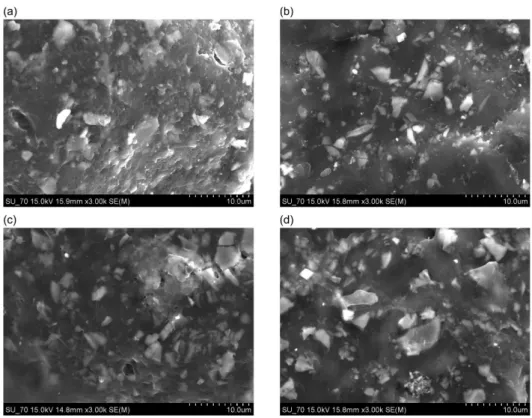
Figures 2a, 2b, 2c and 2d display the SEM of the PA substrate after contact with SBF for 15 and 30 days.
After contact with SBF solution, the electronic microscopy clearly showed that the coating was able to interact with the solution and formed crystals in their surfaces. Crystal size increased with larger contact times, and it is expected to be calcium triphosphate and silicate phosphate, such as Ca5(PO4)2SiO4 and (Ca2(SiO4))6(Ca3(PO4)2)
27 and/or
hydroxyapatite. This is as in our previous work,28 in which
it was observed crystalline phases that were ascribed to hydroxyapatite, using the same synthesis of the present work, but with analysis up to their xerogel.
Thermal analysis (TG/DTA/DSC)
TGA/DTA/DSC curves of the samples before the in vitro test
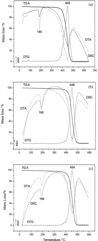
Thermal analyses were employed for the identification of probable changes in the thermal properties of the modified materials. Figures 3a, 3b and 3c present the TGA curves and the corresponding derivates (DTG), DSC and DTA curves for the samples PA, NcP and NsP, respectively.
The DTG and DSC curves reveal that there is a change in the melting point of the PA substrate after coating. PA has a melting point of 185 °C (Figure 3a). Upon coating, its
melting point increases to 190 and 194 °C for the samples NcP and NsP (Figures 3b and 3c), respectively. These results indicate that a coating-substrate interaction takes place for both samples. Moreover, the interaction between PA and the coating in the sample NsP is apparently stronger since the maximum temperature of decomposition observed in Figure 3c is considerably higher. In the literature, there are few works that use the sol-gel methodology to coat a polyamide piece obtained by rapid prototyping. There are also some works that employed thermal analysis and
composites or biocomposites. Zhang et al.29 studied
biocomposites containing different hydroxyapatite (HA)/ polyamide 66 (PA) ratios and observed that the melting point increases when inorganic materials (HA) are added to the organic compound (PA), being in agreement with our work.
TGA /DTA/DSC curves of the samples after the in vitro test
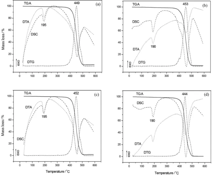
The NcP and NsP samples were placed in SBF in order to assess the probable bioactivity of the coating. The samples remained immersed in SBF for 15 or 30 days.
After contact with SBF, new thermal analyses were carried out for the samples, demonstrating that the coated PA still presents higher melting points than the non-coated PA. This proves that the interaction between the substrate and the coating is considerably strong, and that the coating does not completely dissolve after the immersion of the samples in the SBF solution. The melting point of the sample NcP
increases by 5 ºC after 15 days in SBF (Figure 4a) and then decreases after 30 days in SBF (Figure 4b), but the maximum decomposition temperature is still 4 °C higher than that of the non-coated substrate. Figures 4c and 4d correspond to the thermal analyses obtained for the sample NsP after 15 and 30 days in SBF solution, respectively. The melting point remains unchanged after 15 days, but after 30
days it decreases, being attributed to the partial dissolution of the coating and it is also detected for NcP.
Attenuated total reflectance Fourier transform infrared spectroscopy (ATR-FTIR)
ATR-FTIR spectra of the samples before the in vitro test
Figure 5 displays the ATR-FTIR spectra of PA, NcP and NsP. The spectra evidence changes in the vibration modes of PA upon coating. However, these changes occur in different regions for the NcP and NsP samples, indicating that the sols with and without phosphate ions interact with the substrate differently. There is no displacement of the bands assigned to primary amide C=O vibration at
1633 and 1542 cm-1, suggesting that the interaction between
the substrate and the coating does not take place via this functional group, but that the amide groups of PA are
involved in such interaction. The band at 794 cm-1 indicates
the presence of SiO2 in the coating. The vibration modes
at 3293 and 3090 cm-1 (ascribed to the NH group) and
1059 and 467 cm-1 (assigned to NH
2) are shifted in the
spectrum of NcP compared to the spectrum of PA. These band shifts suggest that there is a weak interaction between
these groups and the substrate.2,3 As for NsP, the shifts in the
bands relative to the amide groups are different from those
observed for NcP. The band at 2028 cm-1 in the spectrum
of NsP may mean that there are protonated nitrogen atoms forming four bonds, and the appearance of the bands at
1338 and 319 cm-1 could also indicate some variation in the
surroundings of the amide groups. Taken together, the FTIR spectral data and the results from thermal analysis suggest that PA-coating interaction in NsP might be stronger compared with the interaction in NcP, probably occurring
via hydrogen bonding in the former case.30,31
The corresponding wavenumbers of characteristic groups for PA without coating and after coating (namely NcP and NsP) before contact with the SBF solution are listed in Table 1.
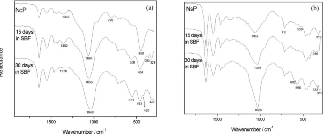
ATR-FTIR spectra of the samples after the in vitro test
There are clear changes in the FTIR spectra of the coated samples after contact with SBF, as can be observed in Figure 6. The spectrum relative to NcP (Figure 6a) shows that bands identified as being due to the interaction between the coating and the amide groups of the substrate
are altered upon contact with SBF. The band at 794 cm-1
corresponding to the presence SiO2 disappears, and the band
at 450 cm-1 ascribed to the presence of the Si
−O−Si coating
is replaced with bands usually relative to the characteristic
C−C=O vibrations of the primary aliphatic amide of the
substrate at 464 and 420 cm-1. These facts could indicate
Figure 4. Thermal analysisof the NcP after 15 (a) and 30 (b) days in SBF and NsP after 15 (c) and 30 (d) days in SBF.
Figure 5. ATR-FTIR spectra of the PA, NcP and NsP.
the dissolution of the silica coating. However, the fact that
the band at 1064 cm-1 shifts to 1040 cm-1 after 30 days in
SBF shows that the Si−O−Si coating is present even after
this period in SBF, and that the polymer network may have suffered some modification. The appearance of the bands at
Figure 6. ATR-FTIR spectra of the NcP (a) and NsP (b) before and after contact with SBF.
Table 1. Characteristic wavenumber for the samples PA, NcP and NsP before contact with the SBF solution
Characteristic groups PA NcP NsP
N–H stretching vibration / cm-1 3293 3299 3292
N–H bending vibration / cm-1 675 678 678
–CH2– stretching vibration / cm-1 2913 2918 2818
–CH– stretching vibration / cm-1 2850 2852 2852
interaction via the amide groups in the NcP sample. The
band at 558 cm-1 present in the spectrum of NcP after 15 and
30 days in SBF indicates the formation of phosphate on the
surface of the sample.14,18
Figure 6b depicts the ATR-FTIR spectra of the NsP sample before and after immersion in SBF. In this case, it can also be observed that the bands previously identified as being due to the interaction between the coating and the substrate undergo modifications. The bands at 1336 and
2025 cm-1 (ascribed to the amide groups) disappear when
the NsP is immersed in SBF, suggesting changes in the initial PA-coating interaction. However, the presence of the bands attributed to amide groups of PA at 360,
336 and 310 cm-1 shows that a PA-coating interaction
still exists. The shift of the band at 1062 cm-1 (assigned to
Si−O−Si) reveals that there were changes in the network
Table 2. Characteristic wavenumbers for the samples NcP(15), NcP(30), NsP(15) and NsP(30) after contact with the SBF solution for 15 and 30 days
Characteristic groups NcP(15) NcP(30) NsP(15) NsP(30)
N–H stretching vibration / cm-1 3286 3286 3292 3292
N–H bending vibration / cm-1 681 681 677 677
–CH2– stretching vibration / cm-1 2919 2919 2918 2918
–CH– stretching vibration / cm-1 2848 2848 2845 2845
–PO
3-4 558 553 − 560
of the coating upon contact with SBF. After 30 days in
SBF, bands attributed to crystalline phosphate14,18 can
be detected at 602 and 560 cm-1 for the NsP sample.
The phosphate crystal can be observed in the SEM micrographs (Figure 2).
The corresponding wavenumbers of the characteristic groups of PA in the coated substrate (namely samples NcP(15), NcP(30), NsP(15), and NsP(30)) after contact with SBF solution for 15 and 30 days are listed in Table 2.
Conclusion
This work reports important results with respect to the coating on organic polymers carried out by the sol-gel process at low temperature. The PA structure here employed is not affected by the methodology used for the coating. The thermal resistance of the polymer increases because of the good adhesion of the coating onto PA.
the coated polymer here prepared is a potential candidate for application as biomaterial for bone replacement.
Acknowledgments
The authors acknowledge Fundação de Amparo à Pesquisa do Estado de São Paulo (FAPESP), Conselho Nacional de Desenvolvimento Científico e Tecnológico (CNPq) and Coordenação de Aperfeiçoamento de Pessoal de Nível Superior (CAPES) (Brazilian research funding agencies) for supporting this work.
References
1. Leeuwenburgh, S. C. G.; Malda, J.; Rouwkema, J.; Kirkpatrick, C. J.; Biomaterials2008, 29, 3047.
2. Shen, J.; Li, Y.; Zuo, Y.; Zou, Q.; Li, J.; Huang, D.; Wang, X.;
J. Biomed. Mater. Res., Part B2009, 91, 897.
3. Wang, H.; Li, Y.; Zuo, Y.; Li, J.; Ma, S.; Cheng, L.; Biomaterials 2007, 28, 3338.
4. Jie, W.; Yubao, L.; Eur. Polym. J. 2004, 40, 509.
5. Zhang, Y.; Hao, L.; Savalani, M. M.; Harris, R. A.; Di Silvio, L.; Tanner, K. E.; J. Biomed. Mater. Res., Part A2009, 91, 1018. 6. Salmoria, G. V.; Leite, J. L.; Paggi, R. A.; Polym. Test.2009,
28, 746.
7. Volpato, N.; Prototipagem Rápida: Tecnologias e Aplicações; Edgard Blücher: São Paulo, Brasil, 2007.
8. Meurer, M. I.; Nobre, L. F. S.; Meurer, E.; Silva, J. V. L.; Santa Bárbara, A.; Oliveira, M. G.; Silva, D. N.; Santos, A. M. B. In
Virtual Modelling and Rapid Manufacturing; Bártolo, P. J.; Batista, F. C., eds.; Taylor & Francis Group: London, 2005, p. 167.
9. Nassar, E. J.; Avila, L. R.; Pereira, P. F. S.; Nassor, E. C. O.; Cestari, A.; Ciuffi, K. J.; Calefi, P. S.; Quim. Nova2007, 30, 1567.
10. Cestari, A.; Bandeira, L. C.; Calefi, P. S.; Nassar, E. J.; Ciuffi, K. J.; J. Alloys Compd.2009, 472, 299.
11. Nassar, E. J.; Nassor, E. C. O.; Avila, L. R.; Pereira, P. F. S.; Cestari, A.; Luz, L. M.; Ciuffi, K. J.; Calefi, P. S.; J. Sol-Gel Sci. Technol.2007, 43, 21.
12. Rocha, L. A.; Molina, E. F.; Ciuffi, K. J.; Calefi, P. S.; Nassar, E. J.; Mater. Chem. Phys.2007, 101, 238.
13. Arcos, D.; Vallet-Regí, M.; Acta Biomater.2010, 6, 2874. 14. Peitl, O.; Zanotto, E. D.; Hench, L. L.; J. Non-Cryst. Solids
2001, 292, 115.
15. Hench, L. L.; Sol-Gel Silica: Properties, Processing and Technology Transfer; Noyes Publications: London, 1998. 16. Wright, J. D.; Sommerdijk, N. A. J. M.; Sol-Gel Materials
Chemistry and Applications, vol. 4; Gordon and Breach Science Publishers: Amsterdam, 2001.
17. Aegerter, M. A.; Menning, M.; Sol-Gel Technologies for Glass Producers and Users; Kluwer Academic Publishers: U.S.A., 2004.
18. Takadama, H.; Kim, H.-M.; Kokubo, T.; Nakamura, T.; Chem. Mater. 2001, 13, 1108.
19. Kawai, T.; Ohtsuki, C.; Kamitakahara, M.; Hosoya, K.; Tanihara, M.; Miyazaki, T.; Sakaguchi, Y.; Konagaya, S.;
J. Mater. Sci.: Mater. Med.2007, 18, 1037.
20. Kawaia, T.; Ohtsukia, C.; Kamitakaharaa, M.; Miyazakib, T.; Taniharaa, M.; Sakaguchic, Y.; Konagay, S.; Biomaterials 2004,
25, 4529.
21. Nassar, E. J.; Ciuffi, K. J.; Gonçalves, R. R.; Messaddeq, Y.; Ribeiro, S. J. L.; Quim. Nova 2003, 26, 674.
22. Bandeira, L. C.; De Campos, B. M.; De Faria, E. H.; Ciuffi, K. J.; Calefi, P. S.; Nassar, E. J.; Silva, J. V. L.; Oliveira, M. F.; Maia, I. A.; J. Therm. Anal. Calorim. 2009, 97, 67.
23. de Campos, B. M.; Bandeira, L. C.; Calefi, P. S.; Ciuffi, K. J.; Nassar, E. J.; Silva, J. V. L.; Oliveira, M.; Maia, I. A.; Virt. Phys. Prototyping2011, 6, 33.
24. Kokubo, T.; Kushitani, H.; Sakka, S.; Kitsugi, T.; Yamamuro, T.;
J. Biomed. Mater. Res. 1990, 24, 721.
25. Yi, Z.; Yubao, L.; Jidong, L.; Xiang, Z.; Hongbing, L.; Yuanyuan, W.; Weihu, Y.; Mater. Sci. Eng., A 2007, 452/453, 512.
26. Jie, W.; Yubao, L.; Yi, H.; J. Mater. Sci.2005, 40, 793. 27. Bandeira, L. C.; Ciuffi, K. J.; Calefi, P. S.; Nassar, E. J.; Adv.
Biosci. Biotechnol. 2010, 1, 200.
28. Bandeira, L. C.; Calefi, P. S.; Ciuffi, K. J.; Nassar, E. J.; Salvado, I. M. M.; Fernandes, M. H. F. V.; Cerâmica 2011, 57, 166. 29. Zhang, X.; Li, Y.-B.; Zuo, Y.; Li, G.-Y.; Mu, Y.-H.; Li, H.;
Composites Part A 2007, 38, 843.
30. Bueno, W. A.; Manual de Espectroscopia Vibracional; McGraw-Hill: São Paulo, Brasil, 1989.
31. Colthup, N. B.; Daly, L. H.; Wiberley, S. E.; Introduction to Infrared and Raman Spectroscopy; Academic Press: San Diego, 1990.
Submitted: October 24, 2011
Published online: March 27, 2012