Article
Electrochemical Impedance Spectroscopy of Dodecylsulphate Doped
Polypyrrole Films in the Dark and Under Illumination
Milena Martinia,Tullio Matenciob, Nicolás Alonso-Vantec, Marco-Aurelio De Paoli*d
a
Departamento de Física Aplicada, Instituto de Física, Universidade de São Paulo, CP 66318, 05315-970, São Paulo - SP, Brazil
b
Departamento de Química, ICEx, Universidade Federal de Minas Gerais, CP 702, 31270-901, Belo Horizonte - MG, Brazil c
UMR-CNRS 6503, Universite de Poitiers, 40, Av. du Recteur Pineau, F-86022 Poitiers, France d
Universidade Estadual de Campinas, Instituto de Química, CP 6154, 13081-970, Campinas - SP, Brazil
Efeitos de morfologia, espessura, oxidação e iluminação dos filmes de polipirrol dopados com dodecilsulfato podem ser observados qualitativamente por EIS e consistem de variações de valores de resistências e capacitâncias de um circuito equivalente proposto, presentes nas interfaces e no interior do material. O circuito se ajusta bem para filmes sintetizados com densidade de carga de 190 mC cm-2. Para filmes mais finos os valores calculados por espectroscopia de impedância eletroquímica (EIS) apresentam desvios provavelmente pela ausência de efeitos difusivos. A oxidação dos filmes causa uma diminuição geral da impedância em toda a faixa de freqüências medidas. Os efeitos de morfologia também são observados em todas as freqüências. Os efeitos de iluminação são reversíveis e aparecem, como esperado, apenas quando o polímero está na forma reduzida. A iluminação diminui a resistência interna e a capacitância de carga espacial e aumenta a resistência de transferência de carga e a capacitância de dupla camada.
The morphology, thickness, oxidation and illumination effects in dodecylsulphate doped polypyrrole films can be qualitatively observed by EIS and consist in variations of interfacial and bulk resistances and capacitances of a proposed equivalent circuit. The circuit well with the measured spectra of films obtained with 190 mC cm-2 of synthesis charge density. For thinner films the calculated values observed by electrochemical impedance spectroscopy (EIS) deviate probably due to the absence of diffusion effects. The oxidation of the films diminishes the total impedance over the entire frequency range. The morphology effects are also observed in the entire spectra. The illumination effects are reversible and are observed as expected only in the reduced form of the polymer. The illumination reduces the internal resistance and the space-charge capacitance and increases the charge transfer resistance and the double layer capacitance.
Keywords: conducting polymer, photoelectrochemistry, eletrochemical impedance spectroscopy
Introduction
Transport and transference processes of electronic and ionic charges of conducting polymers in contact with elec-trolytes are important for their applications in electrochem-istry and photoelectrochemelectrochem-istry. Impedance spectroscopy permits to separate inductive, kinetic, diffusive and charge saturation processes, that take place within the material and at the active interfaces of the system. Different
characteris-tic relaxation times and their dependence upon an a.c. fre-quency of small amplitude applied to the system are the keys for a better comprehension of the phenomena involved in the synthesis of the films and the functioning and ageing of electro- and photoelectrochemical cells built with them.
Double layers with different electrical charges, such the Helmholtz double layer and the Gouy-Chapman region, and a space charge region are formed in a semiconductor electrolyte interface under appropriate conditions. At each of them a dif-ferential capacitance can be associated. When a space charge region with finite length, or depletion layer, is present in the semiconductor material, it determines the general system behaviour, and can be studied in details with the aid of EIS.
Presented at the XI Simpósio Brasileiro de Eletroquímica e Eletroanalítica, Maragogi - AL, Brazil, April 5-9, 1999. Guest editor: Luis Alberto Avaca.
Electrochemical impedance measurements for the determina-tion of the flat band potential in photoelectrochemical sys-tems based on polyaniline1, poly(3-methylthiophene)2 and
polypyrrole3 films were already performed in our laboratory.
Many works are presented in the literature in which the electrochemical properties of polypyrrole and other con-ducting polymers synthesised in different conditions are studied by EIS. Bard and cols.4 have applied the technique
for the first time with polypyrrole, PPy. The authors have shown that PPy films were porous to the electrolyte but electron transfer reactions can also occur at the polymer surface. The decreasing of admittance in potentials more negative than - 0.7 V vs SCE have confirmed the insulating nature of reduced PPy. The authors have used the model of a single pore to discuss the results obtained with imped-ance measurements around +0.1 V vs SCE, neglecting the mass transfer effect.
Using the transmission line model presented by Rubinstein5, Albery and cols.6 have fitted the mobilities of
the charge carriers in the polymer and of the counter-ions in the pores containing solution. Each line could have its own resistance. The results have shown that the two resis-tances were equal, indicating that the motion of the charge carriers in the polymer backbone and of the ions in the solution are coupled. The capacitance, distributed between the two lines is described by Feldberg7. The electron
propa-gation may take place through molecular exchange reac-tions involving conformational changes of the polymer chains. But when the interchain transport is too fast, and the interchain hopping is the rate controlling process, this model cannot satisfactorily describe the experimental im-pedance data.
Waller and Compton8 studied PPy films (0.025 ~ 0.15
mm thick) electrosynthesised on Pt electrodes in the pres-ence of BF4- in acetonitrile, simultaneously by Electron
Spin Resonance and EIS. They found that not only bipolarons but also polarons are involved in the conduc-tivity of PPy. The complex plane plots of the films were dependent upon their doping degree. For applied poten-tials more negative than 0.0 V vs SCE two depressed semi-circles were observed and they were attributed to the double layer at the PPy | Electrolyte interface (low fre-quency) and to the bulk PPy (high frefre-quency). A charge saturation region (at low frequency), a depressed semi-circle (at high frequency) and a straight line (45°) at inter-mediary frequencies were observed at potentials more positive than 0.0 V vs SCE. This line can be interpreted in terms of a reversible reaction involving the diffusion of charge-compensating counter-ions or of porous electrode. The depressed semicircles can be assigned to the rough-ness of the polymer surface.
By controlling the microscopic structure of polypyr-role, with chains growing perpendicularly to the substrate, Naoi and Osaka9 observed that the doping process is
favoured in comparison to a film synthesised normally without structure control. The total impedance in the former case is smaller and diffusion controlled. More re-cently, Naoi and cols10. have demonstrated the influence
of the columnar oriented structures of polypyrrole over the diffusion coefficient, D, and the limiting capacitance, CL, measured by EIS. Potentiostatically synthesised films of polypyrrole (0.2 mC cm-2) in solutions containing
dif-ferent concentrations of the surfactants dodecylsulphate, DS, and dodecylbenzenesulfonate, DBS, above and be-low the critic micellar concentration (c.m.c.), were used. They observed that D and CL values are not linear with respect to DS and DBS concentrations, but show an in-crease of 3 orders of magnitude near the c.m.c. The re-sults were interpreted as an improved cation movement along the oriented columns in the polymer. Otero and Angulo11 have observed that the charge saturation
ca-pacitance, CCS, varies with the potential applied to PPy films obtained in the presence of ClO4- and it is also
pro-portional to their thickness.
The determination of electronic and ionic exchange sites in addition to other diffusion and interfacial parameters was done by impedance measurements in PPy films in the form of modified electrodes (asymmetric configuration) and free membranes (symmetric configuration)12. The films were
electropolymerized in an acetonitrile solution of pyrrole and tetraethylammonium tosylate and the measurements were performed in aqueous medium. It was found that the ionic diffusion coefficient is independent on the film thickness. This indicates that the film structure is maintained during the whole synthesis time. In addition, the authors observed that whatever the film thickness, the nature and concentra-tion of the electrolyte, the electronic diffusion coefficient is always much higher than the ionic one.
Experimental
Synthesis of the films for scanning electronic microscopy
Films of polypyrrole doped with dodecylsulphate, PPy-DS were synthesised galvanostatically on Pt substrates. Three films were synthesised with charge density of 290 mC cm-2 and current densities of 0.1, 1.0 and 5.0 mA cm-2.
Other two films were synthesised with current density of 1.0 mA cm-2 and charge densities of 600 and 1200 mC cm-2.
The samples were metalized by sputtering of Au/Pd before the measurements in a JEOL JSM T-300 Scanning Elec-tronic Microscope operating at 20 kV.
Synthesis of the films for impedance measurements
Four films of polypyrrole doped with dodecylsulphate, PPy-DS, were synthesised galvanostatically on Pt disks (0.125 cm2) in different conditions of applied charge and
current densities (Table 1). The Pt electrodes were previ-ously cleaned by electrochemical treatment in a 0.5 mol L-1
H2SO4 solution. The film thicknes were controlled by the
synthesis charge and were measured with an Alpha-Step 200 Tencor Instruments profilometer. The films were condi-tioned by a series of oxidation / reduction cycles in the electrolyte prior to the impedance measurements.
Results and Discussion
General observations
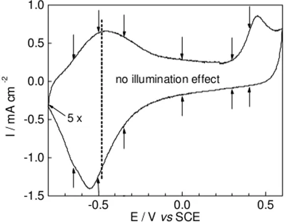
The cyclic voltammetry of a 190 mC cm-2 film (Figure 1)
shows the applied potentials where the effect of illumination was observed (see left side of the figure). At those poten-tials the films are in the reduced state and can generate pho-tocurrent in appropriate conditions14. In this case we can
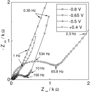
observe the kinetic control region with the presence of a depressed semicircle at higher frequencies, the diffusion control region with the presence of the Warburg section at intermediary frequencies and the limitation charge region at the lower frequencies. When the films are oxidised, the im-pedance of the systems is controlled basically by diffusion and at high oxidation conditions the impedance is controlled by charge saturation (Figure 2). The depressed semicircles seem to be caused by a distribution of parameter values due to surface heterogeneities and are commonly observed in measurements of systems containing polymers.
Table 1. Current, J, and charge, Q, densities and time, t of synthesis used in the preparation of PPy-DS films and their measured thickness, L.
Film J/mA cm-2 t/s Q/mC cm-2 L/µm
1 1,0 1 9 1 9 0,07
2 0,1 190 1 9 0,15
3 1,0 190 190 0,75
4 0,1 1900 190 1,35
-0.5 0.0 0.5
-1.5 -1.0 -0.5 0.0 0.5 1.0
no illumination effect
5 x
I
/ m
A
c
m
-2
E / V vs SCE
Figure 1. Cyclic voltammetry of a PPy-DS film (J = 0.1 mA cm-2; Q = 190 mC cm-2) synthesised on Pt (0.125 cm2). Electrolyte: KCl 0.5 mol L-1 + CrCl3 5 mmol L-1. CE = Pt, RE = SCE. Scanning rate v = 20 mV s-1. The arrows indicate the potentials at which EIS measurements were performed. At -0.8 V "5 x" indicates the alternating measurements in the dark and under illumination.
Electrochemical impedance measurements
The impedance measurements of the samples in a three electrode cell arrangement were performed with a SI 1255 Schlumberger frequency analyser connected to a SI 1286 Schlumberger electrochemical interface and controlled by a computer. The measurements were made in the frequency range of 10 mHz to 65 kHz with amplitude perturbations of 5 mV (rms). For the illumination of the films it we used an halogen lamp (44 mW cm-2 at the sample position) and a
water filter. The cell was composed by a 1 cm2 Pt counter
electrode, SCE as reference electrode and a solution con-taining 0.5 mol L-1 KCl and 5 mmol L-1 CrCl
3 acting as a
redox mediator. The measurements were made at each po-tential (-0.8, -0.65, -0.5, -0.35, 0, +0.3 and +0.4 V vs ECS) with the film in the dark and then under illumination. The results were fitted to proposed equivalent circuits by a non-linear last square algorithm13.
Oxidized PPy-DS
Albery and cols15 proposed equations to describe the
responses of transmission line type for oxidised polypyr-role. In such case the polymeric electronic (RE) and ionic
(RI) resistances and the resistance of the solution (RS) could
be determined from the complex plane representation, us-ing the followus-ing equations:
Rhigh=RS+R∞ (1)
where
and
R|ow=RS+RΣ
3 (3)
with
RΣ=RE+R| (4)
We calculated RE and RI for our oxidised samples and the results are in Table 2. The RS = 9 Ω was determined in a
system without the polymeric film, polarised at +0.4 V16.
Z C L
D
L
= −
1 1
2 12 .
.ω (5)
C L
D R L
L
= 2
3. . (6)
(
)
(
)
C d Z
d L
im −
−
= −
1
1
ω (7)
For the two thicker films the values of diffusion coefficient calculated with Eqs. 5 and 7 are D = 2.3 x 10⁻⁹ (F3) and D = 7.8
x 10-9 cm2 s-1 (F4). When we use the direct determination of
RL (Eqs. 5 and 6), these values of D are respectively 4.5 x 10⁻⁹
and 1.8 x 10⁻⁸ cm2 s-1. The determination of D by ciclic
voltammetry experiments gave 7.9 x 10⁻⁹ cm2 s-1 for a film
synthesised in the same conditions of F4 in good agreement with the impedance results. Thickness and morphology ef-fects can explain the difference of D between films F3 and F4.
Effect of the synthesis conditions
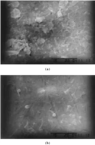
Scanning micrographs (Figure 3) show the effect of charge density on the surface morphology of films of Ppy-DS from galvanostatic synthesis. It is known that thicker films are superficially most irregular than the thinner ones17-21. In the first synthesis stages the polymer is more
compact and our results are in accordance with them. An-other series of micrographs shows that the current density of synthesis have a pronounced effect over the superficial morphology too (Figure 4). In terms of reproducibility of electrochemical properties and conductivity the best syn-thesis currents are 4 to 6 mA cm-2 22. We observe that
lower current densities promote the formation of globules, scales and dendrites with the presence of a large number of pores. Peres and cols.18 attributed morphology alterations
to different lengths of the conjugated polymer chains and to the crystallinity degree of the material. Thickness mea-surements agree with the observation that those films synthesised with higher current densities are more com-pact than those obtained with lower ones (Table 1).
Reduced PPy
For the reduced films (-0.8 < E < -0.5 V vs SCE) the effect of the illumination could be observed in different frequency ranges, depending on the applied potential, thickness and morphology of the films. In order to observe if the illumina-tion effect is reversible we performed ten measurements at the same potential (-0.8 V) alternating dark and illuminated cycles. A plot in the complex plane showing the results of a film synthesised with Q = 190 mC cm-2 and J = 0.1 mA cm-2 Table 2. Electronic (RE) and ionic (RI) resistances calculated for
PPy-DS samples obtained in different synthesis conditions. Film E/V vs SCE RE/Ω RI/Ω
1 +0.3 204 4200
1 +0.4 173 7790
2 +0.3 2 7 5190
2 +0.4 3 4 10500
3 +0.3 3 940
4 +0.4 3 1000
The diffusion coefficient for the ionic transport in the polymeric matrix can be obtained with the impedance mea-surements at low and medium frequencies. At the Warburg section the impedance module is described by Eq. 5. The limiting capacitance values CL are related to a limiting
resistance RL when the impedance measurements are
ex-tended to sufficiently low frequencies at which the lim-ited film thickness effect can be observed as a charge limitation (Eq. 6). In the complex plane it appears as a vertical line (phase angle = π/2). In this case CL can be
calculated with Eq. 7.
0 1 2
0 1 2
- Z
im
/ k
Ω
65.8 Hz 2.3 Hz
1 Hz
100 Hz 10 Hz
534 Hz
0.35 Hz -0.8 V
-0.65 V -0.5 V +0.4 V
Z re / k Ω
(a)
(b)
(c)
Figure 3. Scanning micrographies of PPy-DS films synthesised with synthesis current density J = 1.0 mA cm-2 and charges Q = 290 (a), 600 (b) and 1200 mC cm-2 (c). Bar = 10 mm.
(a)
(b)
Figure 4. Scanning micrographies of PPy-DS films synthesised with charge density Q= 290 mC cm-2 and current densities J = 0.1 (a) and 5.0 (b) mA cm-2. Bar = 10 µm.
0 2 4 6 8
0 2 4 6 8
ILLUMINATED
DARK
2.31 Hz
100 Hz 0.53 Hz
1 st
2 nd
3 rd
4 th
-Z
im
/ k
Ω
Z re / kΩ
Figure 5. Complex plane plots of eight impedance measurements (0.5 Hz < f < 65 kHz) in a reduced PPy-DS film (Q = 190 mC cm-2, J = 0.1 mA cm-2) alternately in the dark and under polychromatic illumination (44 mW cm-2). The measurements were obtained after 12 h of film immersion in the electrolyte and 1 h of polarization at -0.8 V vs SCE.
can be seen in Figure 5. In all cases we could confirm the illumination effect as a generalised decrease of the imped-ance module, with a strong effect over all frequencies of the experiments.
We propose an equivalent circuit to fit our results (Figure 6) that contains an uncompensated resistance RS, a
sub-circuit that consists of the PPy-DS | Electrolyte face and other sub-circuit related to the Pt | PPy-DS inter-face. This circuit is derived from the one proposed by Waller and Compton8, but in our case we have added a constant
phase element, CPE, related to the Warburg element that is
resistance with R = Y0-1; for n = 1 a capacitance with C =
Y0; for n = ½ a Warburg element, and for n = -1 an indutance
with L = Y0-1. ( )
( )
Y∗ =Y j n=Y n n jY n n
+
ω 0 ω 0ω π 0ω π
2 2
cos sen (8)
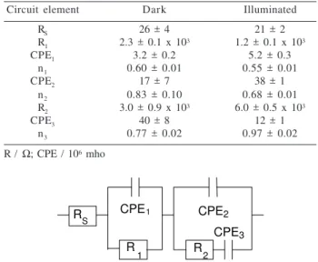
In Table 3 we show the values of the circuit elements calculated for two representative measurements (up triangle) of Figure 5.
RS
R
1 R2
CPE1 CPE2
CPE3
Figure 6. Equivalent circuit used to fit the impedance results. Rs = uncompensated resistance; R1//CPE1 = polymer | electrolyte interface; R2//CPE2 = polymer | electrode interface; CPE3 = difusional control element.
The film porosity affects the impedance responses due to relations between favoured interfaces when the polymer is in its oxidised or reduced form. Neutral PPy is less con-ductive, thus the electrode | polymer and electrode | elec-trolyte interfaces are the most important ones. In this case the charge transfer resistance is high and can control the impedance response. Thus, the diffusional phenomena are visible only in the spectra of the thicker films. If the film is very porous, the surface of the electrode | electrolyte inter-face is larger relatively to the electrode | polymer interinter-face, then in appropriate conditions the charge transfer between the metal and the electrolyte is favoured.
An electrode | polymer interface can be present in conditions of a space charge formation, as in the case of semiconductor thin films. If the time constants of charge transfers between the polymer and the electrode, and between the polymer and the electrolyte, are sufficiently apart we can observe a second distinct semicircle at very high frequencies.
Throughout the calculated time constants of our films we can assign one sub-circuit (R1//CPE1) to the polymer |
electrolyte interface and the other (R2//CPE2) to the
electrode | polymer interface. R1 is related to: a) an
elec-tronic charge transfer resistance during the photoelectro-chemical process and/or b) an ionic charge transfer resis-tance associated to the redox process of the polymer. CPE1
is then related to: a) the space charge capacitance and/or b) the contra-ion accumulation at the polymer | electrolyte in-terface. R2 corresponds to the electronic charge transfer at
the electrode | polymer interface and the CPE2 element is
associated to the double layer capacitance at this interface. The CPE3 element corresponds to a Warburg element,
re-sponsible for the diffusional control of the system. This is reinforced by the observation of the spectra obtained for the thinner films (Figure 7), where no Warburg section is present. The phase and module values are modified at f < 100 Hz, but the kinetic part is not affected. The thicker films fits have a good quality over all frequencies range, as it can be observed in a Bode plot (Figure 8). In this graph the calculated impedance (lines) have a good agreement with the measured module and phase angle.
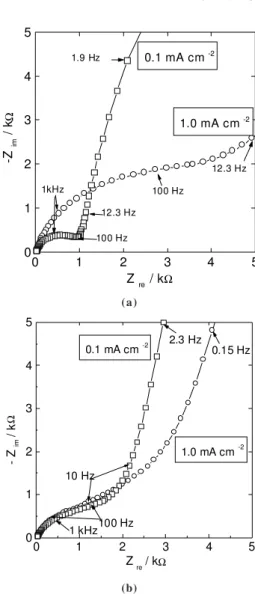
Meanwhile, in the full range of measured frequencies, the phase and module values of the impedance are depen-dent of the morphology of the films, controlled by the syn-thesis charge density (Figure 9-a). Significant alterations in the kinetic and diffusional parameters of the system consti-tuted by the thinner films are observed. The film obtained with J = 0.1 mA cm-2 (less dense, higher free volume) offers
smaller internal resistance, probably because of the poly-mer chains organisation and bigger conjugation length due the slow synthesis. The bigger conjugation length avoids interchain hopping and diminishes the internal resistance. With the increasing time of imersion of the film in the solu-tion, and after a oxidation / reduction cycle, the kinetic part of the impedance response of the two thinner films become comparable, while the intermediary frequencies regions of the spectrum remains dependent on the film morphology (Figure 9-b). For the thicker films we observe an inversion of this trend, as the internal resistance of the films grows and the interface polymer | electrolyte becomes more im-portant (Figure 10).
The circuit elements were calculated for the four films polarised at -0.8 V vs SCE in the dark and under polychro-matic illumination (44 mW cm-2 at the film position) after 12 h
of immersion in the electrolyte. The results are shown in Figure 11, with the various elements values as a function of the polarisation time. The measurements at this potential were initiated at t = 0 without illumination. At t = 0.5 another measurement was made at the same potential, but the film was illuminated. The same procedure was repeated
Table 3. Calculated elements of the proposed equivalent circuit for the 3rd set of measurements of Figure 5.
Circuit element Dark Illuminated
RS 26 ± 4 21 ± 2
R1 2.3 ± 0.1 x 10³ 1.2 ± 0.1 x 10³
CPE1 3.2 ± 0.2 5.2 ± 0.3
n1 0.60 ± 0.01 0.55 ± 0.01
CPE2 17 ± 7 38 ± 1
n2 0.83 ± 0.10 0.68 ± 0.01
R2 3.0 ± 0.9 x 10³ 6.0 ± 0.5 x 10³
CPE3 40 ± 8 12 ± 1
n3 0.77 ± 0.02 0.97 ± 0.02
0 1 2 3 0 1 2 3 152 Hz 1kHz 100 Hz 10 Hz 10 Hz 3.51 Hz
190 mC cm -2 19 m C cm -2
-Z
im
/ k
Ω
Z re / k Ω
Figure 7. Complex plane plots of impedance obtained for PPy-DS films synthesised with J = 1.0 mA cm-2 and Q = 19 and 190 mC cm-2, polarised at -0.8 V vs SCE.
0 1 2 3 4 5
0 1 2 3 4 5 12.3 Hz
1kHz 100 Hz
12.3 Hz
100 Hz 1.9 Hz
1.0 mA cm -2 0.1 mA cm -2
-Z
im
/ k
Ω
Z re / kΩ
10-1 1 10 102 103 104 105 102 103 104 105 phase |Z| ph as e a ng le / de g dark illuminated |Ζ | / Ω
f / Hz
20 30 40 50 60 70
Figure 8. a) Bode plot containing measured (symbols) and calculated (lines) module and phase angles for a PPy-DS thick film (Q = 190 mC, J = 0.1 mA), polarised at -0.8 V vs SCE, in the dark (¨)and under illumination (¡). b) calculated circuit elements.
maintaining the applied potential but alternating dark (t = 1; 2; 3 and 4 h) and illumination (t = 1.5; 2.5; 3.5 and 4.5 h) conditions. For the thinner films the relative errors of the fittings are high. It was not possible to obtain good correla-tions using the proposed circuit of Figure 6, probably due to the absence of diffusional limitations of the impedance. For the thicker ones we note a systematic variation of the calcu-lated circuit elements in exception to the CPE1. The film
synthesised with 0.1 mA cm-2, less dense, requires 1 h of
polarization at -0.8 V until the values of CPE's and R's estabilize. In contrast, the denser film synthesised with 1.0 mA cm-2 require 2 h until the values of the calculated
ele-ments beginn to be reversibly affected by the illumination. Summarising, we have shown that the interfaces that control the charge transfer are: Pt | Electrolyte, which de-termines the ohmic response of the system, Pt | PPy, which can present a space charge region with the presence of a
Figure 9. Complex plane plots of impedance obtained for PPy-DS films synthesised with Q = 19 mC 2 and J = 0.1 and 1.0 mA cm-2, polarised at -0.8 V vs SCE. a) initial; b) after 12 h of immersion in the electrolyte.
(a)
0 1 2 3 4 5
0 1 2 3 4 5 0.15 Hz
1 kHz100 Hz 10 Hz
2.3 Hz 0.1 mA cm -2
1.0 mA cm -2
- Z
im
/ k
Ω
Z re / kΩ
(b)
0 1 2 3 4 5
0 1 2 3 4 5 1kHz 10 Hz 1.23 Hz
1.0 mA cm -2
0.1 mA cm -2
-Z
im
/ k
Ω
Z re / kΩ
0 1 2 3 4 5 0
1 2
R
1
R /
k
Ω
0 1 2 3 4 5
0 10 20 30
R
2
F1 F2 F3 F4
R /
k
Ω
t / h
0 1 2 3 4 5
1 10
CPE
1
0 1 2 3 4 5
1 10 100
CPE
2
CP
E
x
1
0
6 / m
h
o
space charge capacitance at very high frequencies and PPy | Electrolyte, with the formation of double layers and the presence of double layer capacitances at high fre-quencies. These interfaces are not well defined because of the swelling of the films and of the presence of mor-phological alterations in function of their thickness. Be-sides, the bulk of the material can contribute to the total impedance due to the presence of a diffusional control of the ions through the polymer matrix characterised by the Warburg section at intermediary frequencies and the charge accumulation at very low frequencies, characterised by the limiting or geometric capacitance of the film. The effect of the illumination of films synthesised with differ-ent thicknesses and morphologies could be observed through Electrochemical Impedance measurements.
Acknowledgements
DAAD and FAPESP (97/03968-1) are acknowledged for fellowships and FAPESP (96/09983-6) for financial support.
References
1. Neves, S.; Polo da Fonseca, C. N.; De Paoli, M.-A. Synth. Met.1997, 89, 167.
2. Micaroni, L.; Fonseca, C. N. P.; Decker, F.; De Paoli, M. -A. Solar Energy Matter. Sollar Cells 2000, 60, 27.
3. Martini, M.; De Paoli, M. -A. Solar Energy Matter. Sollar Cells 2000, 60, 73.
4. Bull, R. A.; Fan, F. -R. F; Bard, A.J. J. Electrochem. Soc. 1982, 129, 1009.
5. Rubinstein, I.; Sabatini, E.; Risphon, J. J. Electrochem. Soc.1987, 134, 3078.
6. Albery, W. J.; Mount, A. R. J. Electroanal. Chem.
1991, 305, 3.
7. Feldberg, S. W. J. Am. Chem. Soc.1984, 106, 4671. 8. Waller, A. M.; Compton, R. G. J. Chem. Soc., Faraday
Trans. 1989, 1, 977.
9. Naoi, K.; Osaka, T. J. Electrochem. Soc. 1984, 134, 2479. 10. Naoi, K.; Oura, Y.; Maeda, M.; Nakamura, S.
J. Electrochem. Soc. 1995, 142, 417.
11. Otero, T. F.; Angulo, E. Synth.Met. 1992, 51, 87. 12. Deslouis, C.; El Moustafid, T.; Musiani, M. M.;
Tribolet, B. Electrochim. Acta1996, 41, 1343. 13. Boukamp, B.A. Equivalent Circuit Users Manual,
EQUIVCRT, University of Twente, Holland, 1988. 14. Martini, M.; De Paoli, M.-A. Solar En. Mater. Solar
Cells, in press.
15. Albery, W. J.; Chen, Z.; Horrocks, B. R.; Mount, A. R.; Wilson, P. J.; Bloor, D.; Monkman, A. T.; Elliott, C. M.
0 1 2 3 4 5
10 100
CPE
3
t / h
Faraday Discuss. Chem. Soc. 1989, 88, 247.
16. Pickup, P. G. J. Chem. Soc., Faraday Trans. 1990, 86(21), 3631.
17. De Paoli, M. -A.; Peres, R. C. D.; Pernaut, J. -M.; J. Braz. Chem. Soc. 1990, 1, 50.
18. Peres, R. C. D.; Pernaut, J. -M.; De Paoli, M. -A. J. Polym. Sci. (A): Polym. Chem. 1991, 29, 225.
19. Naoi, K.; Oura, Y.; Maeda, M.; Nakamura, S. J. Electrochem. Soc. 1995, 142, 417.
20. Warren, L. F.; Anderson, D. P. J. Electrochem. Soc., Electrochem. Sci. Tech. 1987, 134, 101.
21. Hahn, S. J. Electron. Mater. 1986, 15, 145.
22. Pernaut, J. -M.; Peres, R. C. D.; Juliano, V. F.; De Paoli, M. -A. J. Electroanal. Chem. 1989, 274, 225.
Received: June 16, 1999