*e-mail: [email protected]
1. Introduction
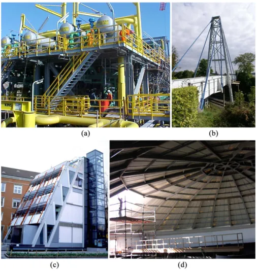
Applications of Glass Fiber Reinforced Polymers (GFRP) elements have grown steadily during the last years, as they became extremely popular in different areas of the aerospace, automotive, marine, O&G (oil and gas) and civil construction industries, namely (iberglass structures): ladders, platforms, handrail systems tank, pipe and pump supports1. The development of GFRP for commercial use occurred in the 1940s, particularly due to interest to the naval industry2. Afterward, the global production speedily increased, reaching the current development in the late 1960s2, when the combination of low material and production costs and advances fabrication of members, inally make polymer production economical and diffused to other ields. Moreover, GFRP presents very lexible design solutions, due to its extraordinary fabrication adaptability, high durability and structural eficiency (strength-to-weight ratio) and its usage also beneits from increasingly low production and erection costs3-6. Figures 1a-d illustrate some applications of structural GFRP.
GFRP is a category of plastic composite that speciically uses glass iber materials to mechanically improve the strength and stiffness of plastics11-13 – the resin provides additional protection to the iber due to the bounding between materials14. Among the different methods of forming GFRP members, the pultrusion, which emerged in the USA in the 1950s1,2, was used to produce the GFRP proile analyzed in this paper – Figura 2 illustrates the two-step fabrication process: (i) impregnation, where the (glass) iber package and slit fabrics material are manufactured and pulled through a wet bath of resin (matrix), formed into the irregular part
shape (i.e., they are bonded with the matrix during molding) and (ii) cure, where obtained saturated material is extruded from a heated mold, while being continuously pulled through die ibrous materials, resulting into some of the end products of pultrusion – structural iberglass predeined shapes (e.g., I-shape, angle, channel and lat sheet proiles) and lengths (a more detailed description of the pultrusion process is provided in Seruti3).
The knowledge about the structural behavior of GFRP members has advanced signiicantly in the last few years and, such advances have been incorporated in design speciications at a fairly rapid rate15-25. Indeed, different characteristics and applications of composites proiles have also been addressed by several authors – while the works of Correia et al.26, Pires27 and Vieira28 examined the mechanical performance of polymeric reinforced with ibers proiles subjected to high temperatures. Other authors29-34 investigated the mechanical behavior of GFRP members. Cardoso35 analyzed the performance and strength of GFRP columns subject to short term concentric compression – most of them dedicated to structural GFRP members. Wu & Bai36 investigated the web crippling behavior of GFRP sections and Wu et al.37 conducted a comparative study on static and fatigue performances of pultruded GFRP joints using ordinary and blind bolts. Recently, Tinô et al.38 assessed the inluence of holes (longitudinal section) in the characteristic fracture in GFRP. Kumar et al.39 described fractographic features observed in aerospace composites failed under tensile loads.
Furthermore, according to the authors’ best knowledge, the amount of experimental data on structural properties of GFRP members produced in Brazil is rather scarce, mostly
Mechanical Properties of Glass Fiber Reinforced Polymers
Members for Structural Applications
Alexandre Landesmanna*, Carlos Alexandre Serutia, Eduardo de Miranda Batistaa
aCivil Engineering Program, Universidade Federal do Rio de Janeiro – COPPE/UFRJ,
Ilha do Fundão, CP 68.506, CEP 21945-970, Rio de Janeiro, RJ, Brazil
Received: September 3, 2015; Revised: September 15, 2015
This paper presents the results of an experimental investigation aiming at determining the mechanical properties of Glass Fiber Reinforced Polymer (GFRP) element produced by the Brazilian industry to classify it for structural applications.. The material samples used in this work were (i) prepared in accordance to ABNT-NBR15708:2011 recommendations, (ii) extracted from web and lange parts of different geometries of one standard H-shaped GFRP single proile, (iii) 2D iber-reinforced ibrous and (iv) exhibited ibers’ orientation on the longitudinal/pultrusion direction. A fairly extensive experimental program was carried out to cover both stiffness and strength structural characteristics of GFRP element, comprising the following mechanical failures modes: (i) direct tension and compression, (ii) two-point lexural bending, (iii) pin-bearing pushed-out and (iv) interlaminar shear deformation. Based on the obtained results, it was possible to conclude that the GFRP element analyzed displays structural classiication compatible to E17 class mechanical requirement.
concerning the specifying and designing using composites (e.g.3) – as they represent a critical issue for evaluation of possible use of GFRP members for structural application3,28. Therefore, the objective of this paper is to provide a contribution towards illing this gap, by presenting and discussing the obtained results of experimental investigation on the mechanical properties of GFRP element produced by a Brazilian industry to classify it for structural applications15,16. In particular, the paper explores the possibility of linking the available results associated with the following mechanical failures modes: (i) direct tension and compression, (ii) two-point lexural bending, (iii) pin-bearing pushed-out and (iv) interlaminar
shear deformation, with respect to recommendations provided by ABNT NBR 15708 codes15,16.
2. Material and Methods
The experimental tests were performed according to recommendations provided by the recently issued Brazilian code for test methods of pultruded shapes (ABNT NBR 15708:2011)15,16 complemented, where applicable, to other current international technical standards (e.g.17-25) at the Laboratory of Structures and Materials of the Civil Engineering Program at Federal University of Rio de Janeiro. The apparatus used in the experimental tests are depicted in Figures 3a-d – details of the performed tests are described in the following subsections.
2.1. Materials
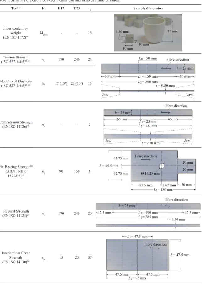
Table 1 summarizes the GFRP samples used and tests performed in this work concerning (i) direct tension and compression, (ii) two-point lexural bending, (iii) pin-bearing pushed-out and (iv) interlaminar shear deformation – also included are the mechanical properties (denoted as “Test Id” for each performed test), the corresponding applicable code, minimum mechanical properties required for each class E17 Figure 1. Applications of structural GFRP – (a) Stairs and decking in Brazil7 (b) Kolding Footbridge in Denmark8, (c) Eyecatcher Building
in Switzerland9, (d) ETAR Vila Moura in Portugal10.
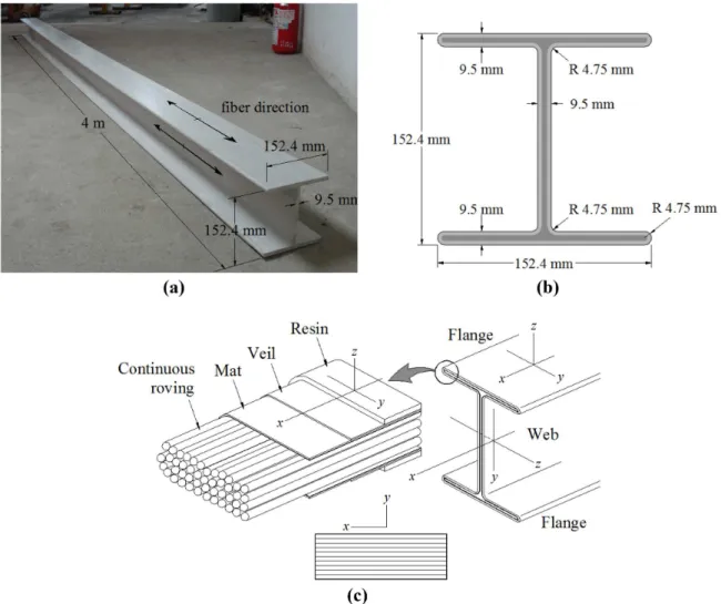
and E23 (in [MPa]), information about the number of samples tested (nS) and main dimensions. All samples used in this work (i) were extracted from web and lange parts of a one standard H-shaped GFRP single proile produced by the Cogumelo Pultrudados Company – with cross-section dimension of 152.4 × 152.4 × 9.50 mm (base × height × thickness) as presented in Figures 4a-c, (ii) were comprised of thermoset polymer matrix resin (thermosetting) vinyl-ester reinforced with glass iber type E-glass (low electrical conductivity glass), (iii) were prepared in accordance to ABNT NBR 15708:201115,16 recommendations and, (iv) exhibited 2D iber-reinforced ibrous with ibers’ orientation on the longitudinal/pultrusion direction (see Figure 4c).
2.2. Methods
The resulting iber content of each specimen is obtained by inserting samples into the INTI mufle furnace and subjected to a constant temperature of 600 °C (Figure 3c), according to the following expression (Equation 1)
( )
% 3 1glass
2 1
m m
M
m m
− =
− (1),
where, m1 are the initial mass of the crucible [g], m2 is the mass of the crucible with the sample before combustion [g], m3 is the inal mass of the crucible with the residue of the sample after iring [g] – m1 to m3 were measured obtain with the Umark 21AO Classe I weighing machine (Figure 3b).
Table 1. Summary of performed experimental tests and samples characterization.
Test(1) Id E17 E23 n
s Sample dimension
Fiber content by weight
(EN ISO 1172)19
Mglass - - 16
Tension Strength
(ISO 527-1/4/5)20-22 σt 170 240 24
Modulus of Elasticity
(ISO 527-1/4/5)20-22 Et 17 (10³) 23 (10³) 15
Compression Strength
(EN ISO 14126)40 σc - - 5
Pin-Bearing Strength(2) (ABNT NBR
15708-5)16
σp 90 150 8
Flexural Strength
(EN ISO 14125)23 σf 170 240 20
Interlaminar Shear Strength
(EN ISO 14130)24
τM 15 25 37
Note: (1) the values of required minimum mechanical properties for classes E17 and E23 are given in MPa and, (2) only samples form the web were used
on the Pin-Bearing Strength tests – one notices that the sample width value (85.5 mm) is higher than the half-width of the lange ~ 152.4/2 = 76.2 mm
an ADS2000 C/A AC2122 model from Lynx Electronic Technology Ltda manufacturer was used for conditioning, data acquisition and digitization. The primary treatment of the experimental data was performed using the computer program Lynx AqDados. The inal processing of the data, with the transformation of experimental data for the chart format, was made in a spreadsheet.
3. Results and Discussion
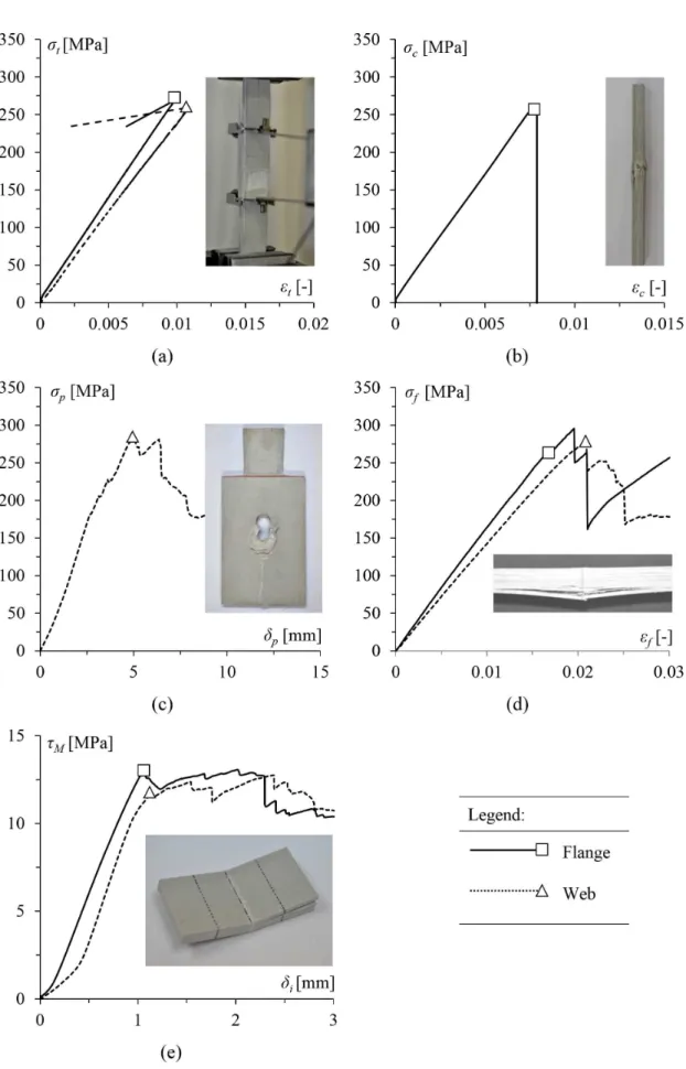
This section presents and discusses the results of the experimental investigation carried out to gather the mechanical properties of GFRP elements produced by the Brazilian industry to classify them for possible structural applications. Figure 5a-e illustrate the typical stress against strain resulting curves and the corresponding aspect of the general failure mode of the GFRP elements tested in the course of this investigation, concerning, as mentioned before, (i) direct tension and compression, (ii) two-point lexural bending, (iii) pin-bearing pushed-out and (iv) interlaminar shear deformation. The observation of the results presented in these igures and Table 3 prompts the following remarks:
(i) First of all, one immediately notices a clear difference (both qualitatively and quantitatively) on the nonlinear behavior of the stress-strain curves before, at and beyond the peak load, concerning the direct tension and compression tests (Figure 5a-b) and their counterparts – two-point lexural bending, pin-bearing pushed-out and interlaminar shear deformation (Figure 5c-e).
(ii) Tension and compression tests exhibit almost identical behaviors and failure modes, which are characterized by a (rather noticeable and almost perfect) linear slope with a visible and well deined ultimate stress (i.e., peak load), followed by a direct linear unloading range. Therefore, precluding the occurrence of any distinguishable intermediate limit point, resulting in a recognizable fragile rupture behavior (Figure 5a-b). Similar behaviors (i.e., orthotropic elastic-fragile) were also reported by Correia41 and, on the present obtained tests’ results, are attributed to a direct consequence of the 2D type iber-reinforced and its orientation on the longitudinal/pultrusion direction
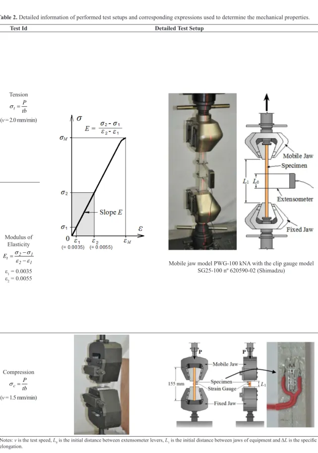
Table 2. Detailed information of performed test setups and corresponding expressions used to determine the mechanical properties.
Test Id Detailed Test Setup
Tension
t
P tb
σ =
(v = 2.0 mm/min)
Mobile jaw model PWG-100 kNA with the clip gauge model
SG25-100 nº 620590-02 (Shimadzu)
Modulus of
Elasticity
2 1
t
2 1
E σ σ
ε ε
− =
− ε1 = 0.0035
ε2 = 0.0055
Compression
c
P tb
σ =
(v = 1.5 mm/min)
(iii) Regarding the pin-bearing pushed-out (Figure 5c), two-point flexural bending (Figure 5d) and the interlaminar shear deformation tests performed (Figure 5e), one immediately notices the similarity between the obtained stress-strain curves and post-peak behaviors. Indeed, conversely to tension/compression direct tests (Figure 5a-b), they exhibit higher post-critical stiffness and much more ductility prior to failure. Moreover, although the nonlinear stress-strain curves display (several) slight peaks, one also observes that the irst limit (distinguishable) point always corresponds to the (highest) peak load (associated to the ultimate stress). Furthermore, the obtained interlaminar shear deformation curves (Figure 5e) provide clear evidence of post-peak behavior, which are associated with progressive stiffness degradation (one observes a multiple shear post-peak behavior, previously reported by Correia41), that leads to several limit points due to partial failures of ibers and matrix layers – this process continues on the unloading range up to the inal rupture of the samples.
(iv) One recognizes a significant influence on the mechanical behavior of the samples from the web and lange parts of the proile – the ultimate strengths from langes’ samples are systematically higher than webs counterparts, recalling that the obtained resulting iber contents (average, standard deviation and maximum/minimum) values are 42.8, 2.4 and 43.1/40 and 44.8, 4.6 and 51.7/40.1 (in %), respectively for web and lange parts. This remarkable difference can be (primarily) explained due to lack of control in the production of the profiles. Indeed, a simplified visual inspection provided evidences of some voids on the samples – these samples were removed priori to tests.
(v) In spite of its limited scope (total of 109 samples analyzed), this study makes it possible to anticipate that (as expected) both the loading type conditions and the iber contents are bound to affect considerably the mechanical properties characteristics of the GFRP elements elastic stiffness and strength, which may have non-negligible implications on Table 2. Continued...
Test Id Detailed Test Setup
Pin-Bearing
p
P td
σ =
(v = 2.0 mm/min)
Flexural
1
f 2
f 2
1
3PL 2bt 6ts L
σ
ε =
=
(v = 6.0 mm/min)
Three/four-point Bending Test Jig for Composite Materials kit 346-53889-XX-5 kN
Interlaminar Shear
M
3P 4bt
τ =
(v = 1.0 mm/min)
Figure 5. GFRP element samples and their general failure mode after tests: (a) direct tension, (b) direct compression, (c) pin-bearing
the corresponding ultimate strength and, therefore, also on its prediction by design methods – this issue deserves further investigation in the future.
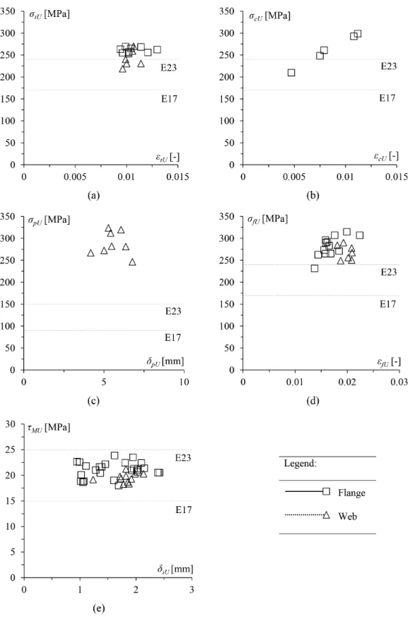
Figure 6a-e plot the obtained ultimate strength against the associated strain, concerning the (i) direct tension and compression, (ii) two-point lexural bending, (iii) pin-bearing
Figure 6. Obtained GFRP element limit results and their general structural classiication: (a) direct tension, (b) direct compression,
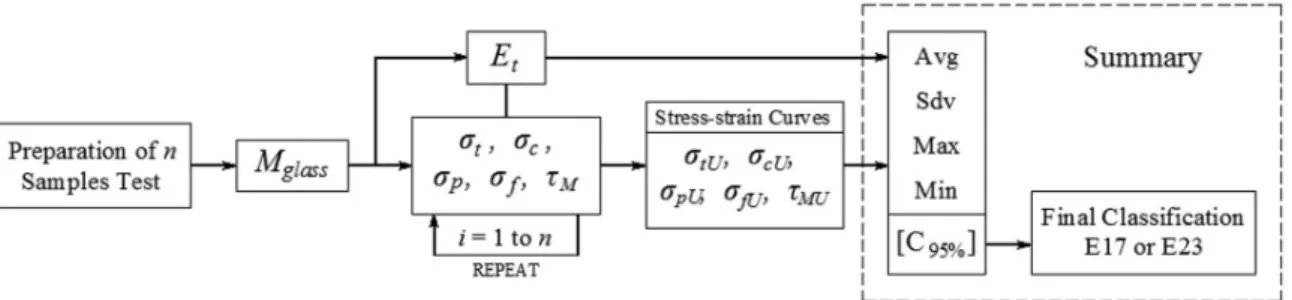
pushed-out and (iv) interlaminar shear deformation tests considered in this work. Moreover, Table 3 summarizes the (i) mechanical properties derived from the performed tests (average, standard deviation and maximum/minimum), (ii) a statistical estimation of the obtained results based on a normal-Gaussian distribution with conidence level 95% (e.g.41) and, (iii) the corresponding inal classiication of the GFRP samples. Finally, Figure 7 illustrates the overall experimental investigation conducted in this work, aiming at determining the mechanical properties of GFRP element produced by the Brazilian industry to classify it for structural applications. The joint observation of these ive plots and results included on Table 3 leads to the following comments:
(i) The ultimate tension strengths results/points (Figure 6a) are fairly well aligned and display an acceptable “vertical dispersion” – this dispersion is a minute for samples originated from langes. In order to quantify the differences, the obtained average, standard deviation and maximum/minimum values are 241.6, 19.9 and 271/219 and 261, 6 and 270/219, respectively for web and lange (see Table 3). One notices that the normal estimation also (262.2 MPa) suggests an E23 classiication (Figure 7). Considering the required minimum limits provided by Tables 2 and 3, the ultimate tension strength can be characterized as E17 class (assuming it on the safe side), even though the lange samples can be clearly classified as E23. On the other hand, as observed in Figure 6b, the 5 compression strength-strain points present both wide vertical and horizontal distribution (in this case, one obtains 262.3, 36 and 299.1/210.1 values for average, standard deviation and maximum/minimum for the compression ultimate strength).
(ii) Despite of the fairly high vertical dispersion, the pin-bearing pushed-out, flexural tests’ results (as illustrated in Figure 6c, d) are clearly above the E23 minimum requirement class – one obtains values ranging from 246.9 to 324.1 and 231.6 to 314.4 values, with an average of 288.1 and 276.9 MPa, respectively for pin-bearing pushed-out and lexural strengths. The characteristics values also validate the above assentation.
(iii) Concerning the interlaminar shear results (Figure 6e), the obtained stress-strains points are visible restricted between the E17 and E23 class limits, with a relatively small vertical scattering – indeed, the points from web and lange mingle quite well. In this present case, one obtains 20.6, 1.5 and 23.9/18 (MPa) values for average, standard deviation and maximum/minimum. Consequently, the interlaminar shear ultimate strength can be assumed to belong to class E17 – one notice that the characteristic value (20.1 MPa) is also between the limits 15-25 MPa for E17-E23 classes. (iv) Regardless of the modulus of elasticity results (iv1)
exhibit a considerable vertical dispersion, (iv2) display a characteristic normal value of 25733 MPa and, (iv3) are (mostly) above the E23 requirement (23000 MPa), the relative high number of points between E17 and E23 suggest a classiication of E17 (on the safe side).
(v) In order to assess the obtained modulus of elasticity values, one applies the rule of mixtures42,43, which states that the overall property in the direction parallel to the ibers may be as high as (Equation 2)
Figure 7. Summary of the performed experimental investigation and inal classiication of Brazilian GFRP element for structural applications.
Table 3. Summary of mechanical properties and inal classiication of GFRP element analyzed.
Test Id C95%
(2) Avg(1) Sdv Max Min E17 E23 Final
σtU 262.2 253.3 16.0 270.6 218.9 170 240 E17
σcU 217.6 262.3 36.0 299.1 210.1 - -
-σpU 265.0 288.1 27.7 324.1 246.9 90 150 E23
σfU 266.8 276.9 21.6 231.6 314.4 170 240 E23
τMU 20.1 20.6 1.5 18.0 23.9 15 25 E17
Et 25733 24503 2222 27696 20378 17000 23000 E17
Note: (1) Avg, Sdv, Max and, Min denote for average, standard deviation, maximum and minimum values for the mechanical properties derived from the performed tests, respectively and, (2) C
( )
t f f m f
E =E V +E 1 V− (2),
where, VF is the volume fraction of the ibers (taken in average as 44%) and, EF and EM are the material property of the ibers and matrix, respectively – which values are assumed4 as 72500 MPa (E-glass) and 3500 (vinyl-ester). As a result, one obtains an estimative of 33860 MPa, considerably higher (~30%0 than the characteristic normal value of 25733 MPa – indeed, this comparison suggested that either the matrix and/or the iber mechanical properties (used in the proile production) should be better quantiied.
(vi) Lastly, in the view of the above results and partial classiication (i.e., for each test performed individually – see Figure 7), it is possible to conclude that the GFRP element analyzed in the course of this investigation, displays structural classiication compatible to E17 class mechanical requirement.
4. Concluding Remarks
This paper reported the available experimental results on the mechanical properties of GFRP elements produced by the Brazilian industry to classify them for structural applications. The samples used in this work were (i) extracted from web and lange parts of a one standard H-shaped GFRP single proile, (ii) made of a composite polymeric reinforced with iberglass type E-glass and, (iii) prepared in accordance to ABNT NBR 15708:201115,16. The inal goal of this research experimental effort is to explore the possibility of linking the obtained mechanical properties with a (forthcoming Brazilian) preliminary design guideline for GFRP members. Out of the various indings obtained in the course of this work, the following ones deserve to be specially mentioned:
(i) There is a clear difference (both qualitatively and quantitatively) on the nonlinear behavior of the stress-strain curves before, at and beyond the peak load, concerning the direct tension and compression tests and their counterparts (i.e., two-point lexural bending, pin-bearing pushed-out and interlaminar shear deformation).
(ii) The resulting iber contents exhibits a signiicant and direct inluence on the mechanical behavior and the ultimate strengths of samples – one observed that the higher is the iber content the higher is the ultimate strength (and elastic stiffness).
(iii) Despite the (general) wide dispersion of the limit stress-strains points, the obtained data (elastic stiffness and strength) bank suggested that the GFRP element analyzed displays structural classiication compatible to E17 class mechanical requirement. Finally, on the view of the inluence of the loading type conditions and the iber contents on the mechanical properties, which may have non-negligible implications on the corresponding ultimate strength and, therefore, also on its prediction by design methods, authors plan to extend the scope of this investigation, to cover additional (i) GFRP samples, (ii) other mechanical properties and (iii) inluence of temperature. Furthermore, since only a relatively small number of samples were presented, more data must be obtained, to either conirm or supplement the indings reported in this work.
Acknowledgements
Authors acknowledge the Cogumelo Industry for providing the samples of GFRP used in the present work. First author acknowledges the Master Degree Scholarship provided by the Brazilian Agency CAPES. Second author gratefully acknowledge the inancial support of FAPERJ (Rio de Janeiro Foundation for Science - Fundação Carlos Chagas Filho de Amparo à Pesquisa do Estado do Rio de Janeiro), through the research project number E26/111.814/2011.
References
1. Daniel I and Ishai O. Engineering mechanics of composite
materials. New York: Oxford University Press; 1994.
2. Palucka T and Bensaud-Vincent B. Composites overview: origins of composites. The Dibner Institute for the History os Science and Technology; 2013. Available from: <http://authors. library.caltech.edu/5456/1/hrst.mit.edu/hrs/materials/public/ composites/Composites_Overview.htm>. Access in: 30 Oct. 2013.
3. Seruti CA. Mechanical characterization and structural
development of the pultruded elements. [Dissertation]. Rio de Janeiro: Universidade Federal do Rio de Janeiro; 2013. In
Portuguese.
4. Bank LC. Composites for construction: structural design with
FRP materials. New Jersey: John Wiley & Sons; 2006.
5. Sousa JP. Durabilidade de peris pultrudidos de viniléster
reforçado com ibras de vidro (GFRP). [Dissertation]. Lisboa:
Instituto Superior Técnico; 2011.
6. Martins LM and Martins B. Manual control of quality and durability of structures in GFRP. [Dissertation]. Lisboa: Instituto
Superior Técnico; 2011.
7. Cogumelo. Projeto realizados. Cogumelo; 2013. Available from: <http://www.cogumelo.com.br/projetos.aspx>. Access in: 08 Mar. 2013.
8. Per Wåhlin´s. Cable-stayed bridges of Europe: a pictorial.
Denmark. Per Wåhlin; 2013. Available from: <http://www. pwpeics.se/denmark.htm>. Access in: 08 Mar. 2013.
9. Fiberline Composites. The eyecatcher building. Fiberline Composites; 2013. Available from: <http://fiberline.com/ eyecatcher-building >. Access in: 08 Mar. 2013.
10. Step. Gallery. Step; 2013. Available from: <http://step.pt/ gallery.aspx>. Access in: 08 Mar. 2013.
11. Callister WD. Materials science and engineering: an introduction.
7th ed. New Jersey: John Wiley & Sons; 2007.
12. Ashby MF and Jones DRH. Engineering materials 2: an
introduction to microstructures, processing and design. 3th ed.
13. Mitchell BS. An introduction to materials engineering and
science for chemical and materials engineers. New Jersey: John Wiley & Sons; 2004.
14. Staab GH. Laminar composites. London: Butterworth-Heinemann; 1999
15. Associação Brasileira de Normas Técnicas – ABNT. NBR 15708-1: 2011: Petroleum and natural gas industries – pultruded shapes - part 1: materials, test methods and dimensional tolerances.
Rio de Janeiro: ABNT, 2011. In Portuguese.
16. Associação Brasileira de Normas Técnicas – ABNT. NBR
15708-5: 2011: Petroleum and natural gas industries – pultruded shapes - part 5: structural shapes. Rio de Janeiro: ABNT, 2011.
In Portuguese.
17. International Organization for Standardization – ISO. ISO
13706- 2: 2002: Reinforced plastics composites – speciications for pultruded proiles – part 2: methods of test and general
requirements. Brussels: ISO; 2002.
18. International Organization for Standardization – ISO. ISO 13706-3: 2002: Reinforced plastics composites – speciications for pultruded proiles – part 3: speciic requirements. Brussels: ISO; 2002.
19. International Organization for Standardization – ISO. ISO 1172: 1998: Textile-glass-reinforced plastics – prepegs, moulding compounds and laminates – determination of the textile-glass and mineral-iller content – calcination methods. Brussels: ISO; 1998.
20. International Organization for Standardization – ISO. ISO
527-1: 1993: Plastics – determination of tensile properties – part 1: general principles. Brussels: ISO; 1993.
21. International Organization for Standardization – ISO. ISO
527-4: 1997: Plastics – determination of tensile properties – part 4: test conditions for isotropic and orthotropic ibre-reinforced plastic composites. Brussels: ISO; 1997.
22. International Organization for Standardization – ISO. ISO
527-5: 1997: Plastics – determination of tensile properties – part 5: test conditions for unidirecional ibre-reinforced plastics composites. Brussels: ISO; 1997.
23. International Organization for Standardization – ISO. ISO 14125: 1998: Fibre-reinforced plastic composites – determinations of lexural properties. Brussels: ISO; 1998.
24. International Organization for Standardization – ISO. ISO 14130: 1998: Fibre-reinforced plastic composites – determinations of apparent laminar shear strength by short-beam method. Brussels: ISO; 1998.
25. American Society for Testing and Materials – ASTM. D3410/
D3410M-03: Standard test method for compressive properties of polymer matrix composite materials with unsupported gage section by shear loading. West Conshohocken: ASTM; 2008 .
26. Correia JR, Gomes MG, Pires JM and Branco FA. Mechanical
behavior of pultruded glass fibre reinforced polymer composites at elevated temperature: experiments and model assessment. Composite Structures. 2013; 98:303-313. http://dx.doi. org/10.1016/j.compstruct.2012.10.051.
27. Pires JMC. High temperature mechanical behavior of glass iber reinforced polymer (GFRP). [Dissertation]. Lisboa: Instituto
Superior Técnico; 2012. In Portuguese.
28. Vieira J. Study of the structural behavior of the pultruded proiles under high temperature effect. [Thesis]. Rio de Janeiro: Universidade Federal do Rio de Janeiro; 2008. In Portuguese. 29. Correia JR, Branco FA, Silva NMF, Camotim D and Silvestre
N. First-order, buckling and post-buckling behaviour of gfrp pultruded-beams. Part 1: experimental study. Computers
& Structures. 2011; 89(21-22):2052-2064. http://dx.doi. org/10.1016/j.compstruc.2011.07.005.
30. Correia JR, Branco FA, Silva NMF, Camotim D and Silvestre
N. First-order, buckling and post-buckling behaviour of gfrp pultruded-beams. Part 2: numerical simulation. Computers &
Structures. 2011; 89:2065-2078.
31. Feo L and Mancusi G. The influence of the shear deformations on the local stress state of pultruded composite Profiles.
Mechanics Research Communications. 2013; 47:44-49. http:// dx.doi.org/10.1016/j.mechrescom.2012.11.004.
32. Guades E, Aravinthan T and Islam MM. Characterisation of the
mechanical properties of pultruded fibre-reinforced polymer tube. Materials & Design. 2014; 63:305-315. http://dx.doi. org/10.1016/j.matdes.2014.06.018.
33. Ascione F. Influence of initial geometric imperfections in the lateral buckling problem of thin walled pultruded GFRP I-Profiles. Composite Structures. 2014; 112:85-99. http://dx.doi. org/10.1016/j.compstruct.2014.02.002.
34. Ascione L, Giordano A and Spadea S. Lateral buckling of pultruded FRP beams. Composites. Part B, Engineering. 2011; 42(4):819-824. http://dx.doi.org/10.1016/j.compositesb.2011.01.015. 35. Cardoso D. Compressive strength of pultruded glass-iber
reinforced polymer (GFRP) columns. [Thesis]. Rio de Janeiro: Universidade Federal do Rio de Janeiro; 2014.
36. Wu C and Bai Y. Web crippling behaviour of pultruded glass fibre reinforced polymer sections. Composite Structures. 2014; 108:789-800.
37. Wu C, Feng P and Bai Y. Comparative study on static and fatigue performances of pultruded GFRP joints using ordinary and blind bolts. Journal of Composites for Construction. 2015;
19(4). http://dx.doi.org/10.1061/(ASCE)CC.1943-5614.0000527. 38. Tinô SRL and Aquino EMF. Fracture characteristics and
anisotropy in notched glass fiber reinforced plastics. Materials Research. 2014;17(6):1610-1619.
39. Kumar MS, Raghavendra K, Venkataswamy MA and Ramachandra HV. Fractographic analysis of tensile failures of aerospace grade composites. Materials Research. 2012; 15(6):990-997.
40. International Organization for Standardization – ISO. ISO
14126:1999: Fibre-reinforced plastic composites - determination of compressive properties in the in-plane direction. London: ISO; 1999.
41. Correia MM. Structural behavior of GFRP Pultruded proiles- experimental characterization and numerical modeling.
[Dissertation]. Lisboa: Instituto Superior Técnico; 2012. In
Portuguese.
42. Jones RM. Mechanics of composite materials. 2nd ed. London: Taylor & Francis; 1999. 519 p.
43. Clark JL, editor. Structural design of polymer composites – eurocomp design code and handbook. London: E & FN Spon;