*e-mail: mbarmouz@ut.ac.ir, m.saeidi@srbiau.ac.ir
1. Introduction
Friction stir welding (FSW) is considerd as an emerging semi-solid state method for joining a variety of alloys and fabrication of metal matrix composites (MMCs). It was invented at The Welding Institute (TWI) of UK in 1991 and was initially applied to aluminum alloys1. Automotive and aviation are among the industries that have paid enormous attention to this process2. In automotive industry, Al
2O3/Al MMCs have been used to replace cast iron components such as pistons, engine blocks, cylinder heads, brake calipers and rotors3. Interestingly, over the recent years, a growing attention is paid to the FSW of aluminum matrix composites. Apart from AA6061/Al2O3/20p[4], AA7005/Al
2O3/10p [5],
AA2124/SiC/25p[6] and AA2009/SiC/15p[7] are it into this category. Pirondi and Collini conducted research into the fracture toughness of AA6061/Al2O3 composite. They realized that the embrittlement effect associated with particle reinforcement might be the rational reason behind inferior fracture toughness of composite joint to base material8.
Meanwhile, the corrosion behaviors of friction stir welded (FSWed) aluminum alloys have been studied by a number of investigators9-11. Shen et al.11 determined corrosion resistance of 5083/6082 joint in NaCl solution. They discovered that the corrosion resistance of FSWed joints was higher than those of both parent materials. On the other hand, Devaraju & Kumar12 reported improved corrosion resistance of AA6061/SiC composite layer produced by friction stir processing (FSP) and they claimed that it could be attributed
to the well-bonding between the reinforcements and matrix and homogeneously distribution of illers.
More recently, based on a novel approach, Bahrami et al.13 applied FSW for joining of two AA7075 plates using SiC reinforcements along the joint line and found promising results from the standpoint of impact toughness. They reported that excellent bonding between reinforcements and the substrate was the reason of positive effect of SiC particles on impact energy absorption. No study to date, however, addressed the joining of dissimilar aluminum alloys based on the foregoing method. Accordingly, the main purpose of this study is to examine the effects of Al2O3 particles on the microstructure, corrosion properties, and fracture toughness of AA7075/AA5083 joint performed via FSW. Excellent corrosion resistance of AA7075-T6 and AA5083-H116 aluminum alloys, along with a unique combination of mechanical properties are the reasons why authors have picked up these alloys as the substrates14-16. Moreover, in some industries such as marine and aviation, sometimes a mixture of various properties is required, particularly with respect to the existed environments. Accordingly, joining high strength and high corrosion resistance alloys could be crucial. Obviously in such industries, metallurgical and mechanical properties of the welded joints are very critical.
2. Experimental Procedure
In this study, 5 mm thick AA5083-H116 and AA7075-T6 aluminum alloy sheets with the chemical composition shown in Table 1 were employed. Prior to use, base materials were
Investigation on AA5083/AA7075+Al
2O
3Joint Fabricated by Friction Stir Welding:
Characterizing Microstructure, Corrosion and Toughness Behavior
Mehdi Saeidia, Mohsen Barmouzb*, Mohammad Kazem Besharati Givic
aYoung Researchers and Elites Club, Science and Research Branch, Islamic Azad University,
Tehran, Iran
bYoung Researchers and Elite Club, Zanjan Branch, Islamic Azad University, Zanjan, Iran cDepartment of Mechanical Engineering, University of Tehran, Tehran, Iran
Received: November 18, 2014; Revised: November 24, 2015
The effects of Al2O3 reinforcements on microstructure, corrosion and toughness properties of dissimilar aluminum alloys joint fabricated by friction stir welding (FSW) technique were explored in this research. AA5083-H116 and AA7075-T6 were selected as the primary base materials. FSW was conducted with and without reinforcing particles through the joint line. Optical microscopy (OM) conirmed uniform distribution of reinforcement particles within the stir zone (SZ) of Al2O3-included specimen. It is demonstrated that the grain size of Al2O3-included specimen in SZ was smaller than that of fabricated without Al2O3. Besides, a comparative corrosion test was performed to assess the effectiveness of Al2O3 particles on corrosion resistance of the joint. The resultant polarization curves gave evidence to a perceptible enhancement in corrosion resistance of the Al2O3-included specimen. Fracture toughness, on the other hand, was examined through impact testing. Surprisingly, Al2O3 -included specimen showed inferior impact toughness due to unsatisfactory bonding between matrix and reinforcements.
cut into 200 × 50 × 5 mm strips. After cutting, proiles were machined on the adjoining side of each strip in dimensions of 2 mm in depth and 0.5 mm in width in a way that when they were put together the groove formed between two strips. Then with the aim of reinforcing the stir zone (SZ), Al2O3 nanoparticles were put along the joint line inside the groove. The properties and micrograph of the as-received Al2O3 reinforcing particles are provided in Table 2 and Figure 1, respectively. The FSW tool was fabricated from H13 hot work steel. Apart from dimensions (in mm), side and top views of the tool are demonstrated in Figure 2. While AA5083-H116 alloy was ixed on advancing side, FSW was conducted at rotational and traveling speeds of 800 rpm and 50 mm/min, respectively.
Potentiodynamic polarization measurements were performed according to the ASTM G69, in a typical three-electrode cell containing a stainless steel plate as an auxiliary electrode17. The potentiodynamic experiments were carried out from −1 V to +1 V with respect to the open circuit potential (OCP) at a scan rate of 1 mV/s. The OCP was monitored for 30 min in 3.5 wt% NaCl solution. Toward this end, one EG&G Princeton applied research Potentiostat/Galvanostat model 273A was employed. A Saturated Calomel Electrode (SCE) was utilized as a reference electrode. In order to boost the experimental results correctness, three corrosion tests were conducted at room temperature (25 °C) on each sample and the electrolyte was changed after each experiment. On the other hand, impact tests were performed at room temperature employing CEAST Resil Impactor machine. Following instructions in ASTM E23, Izod-type Impact test specimens were prepared and tested18. The average value of three specimens was reported as the result of each impact test.
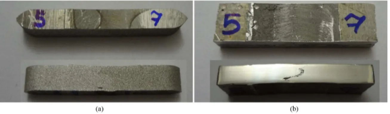
The specimens for metallographic and corrosion examinations were cross-sectioned perpendicular to the welding direction and prepared for microstructural investigation. The specimens before preparation are shown in Figure 3. The corrosion specimens were polished but not as much as metallographic samples. Following preparation, metallographic specimens were etched 15 s with Poulton and Keller reagents. Recent reagents are commonly used as etchant for AA5083 and AA7075, respectively19. Moreover, scanning electron microscopy (SEM) and optical microscopy (OM) techniques were employed for microstructural characterization. It is worth to know that the linear intercept method was used to measure the specimens’ grain size.
3. Results and Discussion
3.1. Macro and microstructural observations
It is reported by Johnson & Threadgill20 that the locations of two dissimilar alloys exert a signiicant effect on material low pattern and the resultant weld quality. They noticed that better welds produced when low-strength material placed on the advancing side. This is why AA5083-H116 was situated on advancing side in this research. Macrostructural sections
are exhibited in Figure 4 which materials lows are evident in these macrographs. The absence of tangible defects in stir zones suggests suitable material low around the pin tool and this implies the soundness of FSWed joints. Formation of elliptical nugget zone was seen in the middle of the joint for all the samples. The shape of SZ depends on the processing parameters, tool geometry, work-piece temperature and thermal conductivity of the material21. Since the both nugget zones are extremely similar in appearance, it could be inferred that the addition of reinforcement particles does not have a major effect on the nugget’s shape.
Various areas of the Al2O3-free joint are addressed in Figure 5, namely: SZ, heat affected zone (HAZ), and base material. It is worth to mention that thermomechanically affected zone (TMAZ), however, is barely discernible in Figure 5. Regarding the SZ of unreinforced joint and base material structures, it was observed that grain size is decreased Table 1. Chemical composition of the base materials.
Base materials Mg Zn Mn Fe Cu Si Ti Al
AA5083-H116 4.45 0.04 0.44 0.33 0.07 0.22 0.05 Balance
AA7075-T6 2.4 5.7 0.17 0.18 1.55 0.06 0.01 Balance
Table 2. Properties of Al2O3 nano-particles.
Purity Particle size (APS) Type Color
99+% 20 nm Gamma White
Figure 1. Micrograph of the as-received Al2O3 nanoparticles.
considerably from 22 and 160 µm in AA5083 and AA7075, respectively; to 6 µm.
Higher magniication of SZ microstructure for this sample including ine equiaxed grains is presented in Figure 6a. As a matter of fact, during friction stir welding, material undergoes severe plastic deformation at elevated temperature which results in the formation of new nucleation sites which make the grains size smaller. This phenomenon is known as dynamic recrystallization (DRX) which occurs during straining of metals at high temperature, characterized by a nucleation rate of low dislocation density grains and a posterior growth rate that can produce a homogeneous grain size when equilibrium is reached22-24. Figure 6b, on the
other hand, shows the SZ microstructure of Al2O3-included specimen which implies that grain size of this specimen is smaller than that of Al2O3-free specimen. The main reason behind this phenomenon is the existence of reinforcement particles acting as nucleation sites. Moreover, they suppress grain boundaries movements and therefore limit grain coarsening which this phenomenon is known as pinning effect21. As a result of pinning effect along with dynamic recrystallization, more and smaller grains are formed within the SZ of Al2O3-included specimen. It is noticeable that the input heat through the FSW is the effective factor to anneal the grains and make increase in grain size but the abovementioned factors are dominative in governing the grain size variation for this specimen.
Figure 7 shows the SEM image of the stir zone for the Al2O3 included specimen which is dealing with uniform distribution of Al2O3 particles in the processed area. According to Figure 7, Al2O3 cluster size varied in the range of 160 to 290 nm. Based on Zener equation, dz = 4r/3vf, limiting grain size (dz) was calculated in the Al2O3-included specimen21. In this equation, r and v are the radius and volume fraction of reinforcements, respectively. The volume fraction of the reinforcement was calculated based on the proportion of groove area to pin area which measured to be 0.03. The measured limiting grain sizes were 5.3 and 9.6 µm with the average of 7.3 µm. Comparing to the grain size measured based on linear intercept method in metallography section, there is no big difference.
3.2. Corrosion behavior
Figure 8 illustrates the polarization diagram for FSWed specimens. Along with corrosion potentials (Ecorr) and exchange current densities (Icorr) of FSWed specimens, Epit was also extracted from the diagram. To draw a comparison, Ecorr and Icorr of the base materials are provided in Table 3. For the FSWed specimen, small grains formed within the SZ resulted in grain boundaries fraction increment which is thermodynamically susceptible to corrosion. Therefore, iner microstructure of the FSWed zone causes poorer corrosion behavior compared to the base metal25. From Table 3, it is clear that the corrosion resistances of the both FSWed specimens are less than that of each base material.
Grain sizes in the SZ of reinforced and unreinforced specimens were 4 and 6 µm, respectively. However, Icorr obtained from reinforced specimen was negligibly lower Figure 3. specimens’ shape used for (a) metallography and (b) corrosion.
Figure 4. Macrographs of FSWed specimens: (a) Al2O3-free;
(b) Al2O3-included.
than that of the unreinforced specimen. In other words, the corrosion resistance of Al2O3-included specimen was slightly superior to that of the Al2O3-free specimen. This result is in good agreement with that of gained by Devaraju & Kumar12 in the case of 6061-T6/SiCp composite produced via FSP. At mentioned work the improved corrosion resistance of SZ was attributed to uniform distribution of reinforcement particles as well as satisfactory bonding between reinforcements and the matrix. In addition, both specimens showed almost identical Epit, Table 3. It is understood that the Al2O3 reinforcements usually do not have a signiicant effects on pitting potentials in chloride solutions3.
Figure 9 shows the optical micrograph of corroded surface in Al2O3-free specimen. Brighter appearance associated with AA5083 conirms its superior corrosion resistance to AA7075. The 7xxx wrought alloys, because of their zinc contents, are anodic to aluminum alloys of other series. Besides, the presence of copper element in AA7075 is another reason which is responsible for its weak corrosion resistance3. Taking a closer look to Figure 9 revealed that chemically attacked regions are mainly located around precipitates. Indeed, corrosion potential of the second phase is not the same as the parent phase3. Accordingly, precipitates in heat-treatable side of the joint i.e, AA7075-T6, are preferable sites for Figure 6. SZ micrograph of the (a) Al2O3-free and (b) Al2O3-included specimens.
Table 3. Corrosion potentials and exchange current densities of FSWed joints and primary alloys.
Sample Ecorr (V) Icorr (A/cm
2) E
pit (V)
Al2O3-free weld –1.27 5 × 10
–5 –0.815
Al2O3-included weld –1.24 3 × 10
–5 –0817
AA5083-H116 –1.16 1 × 10⁻⁵
-AA7075-T6 –1.13 2 × 10⁻⁵
-Figure 7. SEM image of the Stir zone for the Al2O3-included specimen.
Figure 8. Polarization curves obtained from the SZ of Al2O3-free and Al2O3-included specimens.
aluminum alloy, no precipitate is formed in AA5083 section. Consequently, as a result of homogenous microstructure, corrosion attacks are avoided in AA5083 side of the joint.
3.3. Fracture toughness
Impact test results are presented in Figure 10. It was expected that Al2O3-included joint must had higher fracture toughness than Al2O3-free specimen due to this fact that former one had smaller grain size and consequently higher strength. However, on the contrary; at current work the specimen FSWed with presence of the Al2O3 particles showed the least fracture toughness. This is because of the fact that although adding the Al2O3 particles inside the metallic matrix improves the strength and reduces the grain size but presence of the nano-iller inside the matrix increases the possibility of crack propagation as a result of impact test.
Figure 11 shows macroscopic fracture surfaces of impact specimens. As it is indicated, dark surfaces depict the presence of Al2O3 particles in Figure 11b. At a higher magniication, fractured surfaces were further studied via SEM in Figure 12. Fracture micrograph of Al2O3-free specimen is indicative of its brittle fracture as well.
Figure 10. Impact energy of Al2O3-free and Al2O3-included specimens.
Figure 11. Fracture surface of impact test specimens: (a) Al2O3-free; (b) Al2O3-included.
Figure 12. SEM image of fracture surface for impact test of the specimens: (a) Al2O3-free; (b) Al2O3-included. corrosion attack. Paglia & Buchheit26 observed similar
Indeed, the absence of voids and dimples on fracture surface suggests brittle mode. On the other hand, reinforcement particles are obviously emerged in fracture micrograph of Al2O3-included specimen (Figure 12b). As a matter of fact, loose bonding of reinforcements with the substrate and probable clusters aggregation reduced the required fracture energy. This result is against Bahrami et al.13 achievements in the case of AA7075 joint reinforced with SiC nanoparticles. As it is addressed, the reason why they found higher fracture toughness for SiC-included specimen was the excellent bonding between reinforcements and the matrix. Thus, the inferiority of current bonding with respect to the foregoing one could be because of higher wettability of SiC particles with matrix compared to that of Al2O3. Therefore, in this case the de-bondings between the matrix and Al2O3 powders act as crack propagation sites which weaken the impact strength of the specimen.
4. Conclusions
In current study, Al2O3 nanoparticles were compressed embedded into the joint path of AA5083 and AA7075 sheets. For comparison, friction stir welding was conducted without incorporating particles and in brief following results could be mentioned:
1. Joining the AA5083 and AA7075 using FSW leads to dramatic reduction of grain size in the stir zone and this reduction in grain size was more tangible for the specimens containing Al2O3 as reinforcement particles.
2. Sound and defect free weld was performed in spite of presence of reinforcements in the stir zone.
3. Presence of Al2O3 particles leads to improve the corrosion resistance of the joint when compared to that of welded joint without reinforcements.
4. Fracture toughness of the reinforced FSW was diminished compared to unreinforced joint which could be due to the weak interface of reinforcements and substrate and probable clusters aggregation.
Acknowledgements
The authors gratefully acknowledge the assistance of the Azad University (IAU) and University of Tehran laboratories. It is quite a justice to give a galaxy of heartfelt thanks to all memorable attempts of Dr. Mohammad Kazem Besharati Givi.
References
1. Mishra RS and Ma ZY. Friction stir welding and processing. Materials Science and Engineering R Reports. 2005; 50(1–2):1-78. http://dx.doi.org/10.1016/j.mser.2005.07.001.
2. Yau Y, Hussain A, Lalwani R, Chan H and Hakimi N. Temperature
distribution study during the friction stir welding process of Al2024-T3 aluminum alloy. International Journal of Minerals, Metallurgy, and Materials. 2013; 20(8):779-787. http://dx.doi. org/10.1007/s12613-013-0796-2.
3. Cramer SD and Covino BS. Corrosion: fundamentals, testing, and protection. Materials Park: ASM International; 2003. ASM Handbook, 13A.
4. Ceschini L, Boromei I, Minak G, Morri A and Tarterini
F. Microstructure, tensile and fatigue properties of AA6061/20vol.%Al2O3p friction stir welded joints. Composites. Part A, Applied Science and Manufacturing. 2007; 38(4):1200-1210. http://dx.doi.org/10.1016/j.compositesa.2006.06.009.
5. Ceschini L, Boromei I, Minak G, Morri A and Tarterini F.
Effect of friction stir welding on microstructure, tensile and fatigue properties of the AA7005/10vol.%Al2O3p composite. Composites Science and Technology. 2007; 67(3-4):605-615. http://dx.doi.org/10.1016/j.compscitech.2006.07.029. 6. Uzun H. Friction stir welding of SiC particulate reinforced
AA2124 aluminium alloy matrix composite. Materials & Design. 2007; 28(5):1440-1446. http://dx.doi.org/10.1016/j. matdes.2006.03.023.
7. Feng AH, Xiao BL and Ma ZY. Effect of microstructural evolution
on mechanical properties of friction stir welded AA2009/SiCp composite. Composites Science and Technology. 2008; 68(9):2141-2148. http://dx.doi.org/10.1016/j.compscitech.2008.03.010.
8. Pirondi A and Collini L. Analysis of crack propagation resistance
of Al–Al2O3 particulate-reinforced composite friction stir welded butt joints. International Journal of Fatigue. 2009; 31(1):111-121. http://dx.doi.org/10.1016/j.ijfatigue.2008.05.003.
9. Kang J, Fu R, Luan G, Dong C and He M. In-situ investigation
on the pitting corrosion behavior of friction stir welded joint
of AA2024-T3 aluminium alloy. Corrosion Science. 2010; 52(2):620-626. http://dx.doi.org/10.1016/j.corsci.2009.10.027.
10. Venugopal T, Srinivasa Rao K and Prasad Rao K. Studies on
friction stir welded AA 7075 aluminum alloy. Transactions of the Indian Institute of Metals. 2004; 57(6):659-663.
11. Shen C, Zhang J and Ge J. Microstructures and electrochemical
behaviors of the friction stir welding dissimilar weld. Journal of Environmental Sciences. 2011; 23(Suppl):32-35. http://dx.doi. org/10.1016/S1001-0742(11)61072-3. PMid:25084589.
12. Devaraju A and Kumar A. Dry sliding wear and static immersion corrosion resistance of aluminum alloy 6061-T6/SiC p metal matrix composite prepared via friction stir processing. International Journal of Applied Research In Mechanical Engineering. 2011; 1(2):62-68.
13. Bahrami M, Helmi N, Dehghani K and Givi MKB. Exploring the effects of SiC reinforcement incorporation on mechanical properties of friction stir welded 7075 aluminum alloy: fatigue life, impact energy, tensile strength. Materials Science and Engineering A. 2014; 595:173-178. http://dx.doi.org/10.1016/j. msea.2013.11.068.
14. Hatamleh O, Lyons J and Forman R. Laser and shot peening
effects on fatigue crack growth in friction stir welded 7075-T7351 aluminum alloy joints. International Journal of Fatigue. 2007; 29(3):421-434. http://dx.doi.org/10.1016/j.ijfatigue.2006.05.007.
15. Hatamleh O, Singh PM and Garmestani H. Corrosion susceptibility of peened friction stir welded 7075 aluminum alloy joints. Corrosion Science. 2009; 51(1):135-143. http:// dx.doi.org/10.1016/j.corsci.2008.09.031.
16. Choi D-H, Ahn B-W, Quesnel DJ and Jung S-B. Behavior
of β phase (Al3Mg2) in AA 5083 during friction stir welding.
Intermetallics. 2013; 35(0):120-127. http://dx.doi.org/10.1016/j. intermet.2012.12.004.
18. American Society for Testing and Materials – ASTM. E23-09: standard test method for notched bar impact testing of metallic materials. West Conshohocken: ASTM; 2009. Annual Book of ASTM Standards.
19. Dolatkhah A, Golbabaei P, Besharati Givi MK and Molaiekiya F. Investigating effects of process parameters on microstructural and mechanical properties of Al5052/SiC metal matrix composite fabricated via friction stir processing. Materials & Design. 2012; 37(0):458-464. http://dx.doi.org/10.1016/j.matdes.2011.09.035.
20. Johnson R and Threadgill P. Friction stir welding of magnesium alloys. Materials Science Forum. 2003; 419-422:365-370. http:// dx.doi.org/10.4028/www.scientific.net/MSF.419-422.365.
21. Zohoor M, Besharati Givi MK and Salami P. Effect of processing
parameters on fabrication of Al–Mg/Cu composites via friction stir processing. Materials & Design. 2012; 39:358-365. http:// dx.doi.org/10.1016/j.matdes.2012.02.042.
22. Morisada Y, Fujii H, Nagaoka T and Fukusumi M. MWCNTs/ AZ31 surface composites fabricated by friction stir processing.
Materials Science and Engineering A. 2006; 419(1-2):344-348. http://dx.doi.org/10.1016/j.msea.2006.01.016.
23. El-Rayes MM and El-Danaf EA. The influence of multi-pass friction stir processing on the microstructural and mechanical properties of Aluminum Alloy 6082. Journal of Materials Processing Technology. 2012; 212(5):1157-1168. http://dx.doi. org/10.1016/j.jmatprotec.2011.12.017.
24. Humphreys F and Hatherly M. Recrystallization and related annealing phenomena. Oxford: Elsevier; 2004. 658 p.
25. Fahimpour V, Sadrnezhaad SK and Karimzadeh F. Corrosion
behavior of aluminum 6061 alloy joined by friction stir welding and gas tungsten arc welding methods. Materials & Design. 2012; 39(0):329-333. http://dx.doi.org/10.1016/j.matdes.2012.02.043.