Corresponding author: [email protected] ENSP-Congo Brazzaville
Application report
Th e H igh V olt a ge Line Be com e s a Pow e r D ist r ibu t or : A Su cce ssfu l
Te st in Con go- Br a z z a ville
J
E
S
Journal of Electrical Systems
The high line voltage passes over the head but we don’t have electricity to have our mill functioned, we continue to live without the power! In many developing countries, we have a lot of high lines voltage which cross many regions to supply electricity to the main towns or connect to networks the distanced electric stations. These booked lines for supplying electricity to big towns cross a lot of villages whose people broadly poor hope to be supplied with electricity without a suitable solution. However it seems very deplorable that the power conducted by these lines doesn’t profit to surrounding population. Unfortunately, for these villages, the use of classical stations is too expensive to the power distributors because of high cost of investment and production for these potential scattered consumers with the feeble demand of electricity.
This paper presents the original solution, settled in 2002 in one of the village located in Congo Brazzaville, and continues to function correctly. It is a new power transformer with one phase called PLX which is connected on one phase of the high line voltage 220kV and which produces extraordinary the low voltage 230 V directly useful by the rural population. This conceived sample for the rural electrification has been dimensioned for the power of 50kVA. A cheap and resistant advice! It requires a large popularization and mainly in sub saharian Africa that has got many opportunities. Outside the role of conduction of the power, the high line voltage distributes it.
Keywords: Rural electric distribution, One phase transformer, Voltage measurement transformer.
1. INTRODUCTION
existing technology of SF6 inductive voltage transformer in order to supply 50 kVA instead of a few VA. The paper will present the problems met during the design of this specific installation compared to classical substation, and the results of first years of use.
2. THE PROBLEM AND ITS POTENTIAL SOLUTIONS
2.1 The Problem
In many countries throughout the world there are some regions where the distribution network is not developed mainly because of very dispersed and low load level compared to the investment needed to supply them. In some of these locations, it is remarkable to notice that HV trunk line are going through these region but cannot feed any of the small villages or farms leaving close to such important lines (220, 400 and 735 kV). Such HV lines are bringing power from large power station (hydraulic f.e.) to large town some hundreds of km far away. If such a situation is not common in Europe, it is a very common one in Africa, Canada, Russia, China ... The lack of power may have dramatic effect on social life, pushing young people out of their community to go where development is possible and more comfort available. No power means limited economic activity, limited access to water and no possible development. Such a situation is particularly sad for African communities, like in Congo-Brazzaville where only 2% of the rural population has access to electricity, despite some existing long 220 kV OHL going through the country, bringing power from Inga (RDC) and from some few local hydraulic plants to Brazzaville and Pointe Noire. Hundreds of km of HV lines exist with very limited loads and hanging over a very large number of small villages splitted all around the country, many of them being not so far from such trunk lines. Access to petrol in remote location is also a problem so that even local power is not possible most of the time. So they have to live without lighting, without fridge (to maintain food in good conditions) and have to walk several km every day to bring bad water from dirty river. That was the situation of MAKOLA, 30 km far from Pointe Noire in Congo-Brazzaville. About 500 people are leaving there in a complete poorness, a few meters away from a 220 kV trunk line. The amount of power needed has been evaluated by UNESCO to about 50 kVA as a first short term target.
2.2 Potential Solutions
As alternatives, we may imagine capacitive or inductive dividers, or an original way described first by BG CHECO [1] pumping energy from isolated earth wire by natural coupling with phase wire. These are existing complex solutions which need significant maintenance, appropriate compensation and protection scheme.
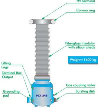
Fig. 1: The SF6 small power transformer used in Makola (50 kVA): Primary voltage:
220 kV/ 3, Secondary voltage: 230 V.
2.3 Our Choice
3. INSULATION COORDINATION
A small load, like ours, cannot disturb the HV trunk line, so that the installation must be designed in that way. The region of installation has a very high keraunic level (>100) and it is known that equatorial regions may be subject to very strong lightning strokes, as well as heavy rain and sand pollution. The transformer has been designed using IEC recommendation to sustain very high level of such overvoltage (1050 kV in full wave, 1205 kV in chopped wave). Moreover 50 Hz overvoltages may occur frequently in such network (Ferranti effect and others) so that 1.5 Un during 8 hours have been chosen for our apparatus. Last but not least the level of partial discharge has been voluntarily chosen at a very low rate. Obviously a surge arrester is protecting the installation, this last being chosen “appropriate”. Secondary windings have been designed to sustain 3 kV insulation level at 50 Hz and this level is also protected by appropriate surge arrester. So called “permanent” 50 Hz overvoltages is typical 1.05 pu and has been taken into account in the choice of the arrester.
4. GROUNDING, STEP AND TOUCH VOLTAGES
Grounding problems are critical in these regions, because soil resistivity is very high during dry season. We have measured, up to 10 m deep (4 point method) about 3500 Ω.m, which is more than 30 times the classical values used in the standard.
Following the IEEE 80 guide for safety in AC substation grounding, admissible step and touch potential may be defined as follows (ρs is the superficial soil
resistivity in Ω.m, and the fault duration (s)):
Tolerable step voltage (V):
116 0, 7 s s
U
t
+ ρ
= (1)
Tolerable touch voltage (V):
116 0,17 s
t
U
t
+ ρ
= (2)
The factor 116 is a body factor introduced by Dalziel and considered here as the lowest one (valuable for body weight of 50 kg). Which means, for our data (short-circuit duration about 0.5 s and resistivity about 3500 Ω.m):
- Maximum tolerable step voltage: 2800 Volts
Fig. 2: Measure of steps voltage during the inauguration.
4.1 Problems to Consider
i) short-circuit phase-to-ground on the 220 kV line (estimated at max 360 A)
ii) short-circuit phase-to-ground on our installation
iii) permanent ground voltage under max load
iv) lightning on 220 kV earthwire
v) lightning on 220 kV phase wire
4.2 Questions
- What would be the step and touch voltage in the direct vicinity of our installation?
- What would be the problem for the distribution network and for the customers connected to it?
And the open design questions are:
- How to manage the earthings (tower, HV side, LV side, customer side)?
4.3 Solution
After deep analysis of all risks, the final solution is detailed on fig. 2:
- LV ground (for customers) is made of 200 m raw copper conductor installed 0.6 m deep, just along our aerial distribution network.
- LV and HV earthing are connected through an arrester able to sustain up to 3 kV at 50 Hz.
- Secondary windings of the PLX are protected by parallel arrester to limit overvoltages to 2 kV, similar arrangement installed at the customer side
RT3
Fig. 3: the grounding system of Makola.
In any case of 50 Hz short-circuit (OHL phase or in our installation), such a system will help to limit step and touch potential in the PLX vicinity and to avoid such over voltages to be transmitted to LV side.
In case of lightning, we cannot avoid that overvoltages may be transmitted, but only the high frequency components will be transmitted, those which are rapidly damped.
4.4 Tests
We obviously performed some tests before commissioning. This has been done in several ways:
- Without tower connection (our system cannot work with such a connection, because all towers of the line are in parallel and such sensibility cannot be reached with our system, but it is clear that the coupling obviously limit the earth resistance to a lower limit that the one we have measured without that connection), we investigated the measurement of ground resistance by the three point method, obtaining, about 35 ohms for the HV earthing grid. The LV earthing conductor was measured at 25 ohms about.
actual step and touch potential by using proportional law between injected current and actual short-circuit (one-phase to ground) in the worst network configuration. Such a method confirms that our former values for earthing resistance may be decreased to 20 ohms.
The worst step voltage has been observed just next to the concrete pad and would be about 2600 V for 360 A short-circuit value, as estimated based on the HV network in Congo-Brazzaville (we are very far from power units).
The worst touch voltage is about 300 V on the fence around the PLX in the same situation.
The vicinity of the PLX is strictly forbidden in case of thunderstorm.
On the customer side, the network is designed with two twisted isolated 70 mm2 Al conductor distributed on wooden poles, with an earth connection (to our buried raw copper conductor) every three poles.
5. THE LOAD AT MAKOLA
As stated, we measured on August – September 2005 current and voltage on the LV side to have access to any troubles. The following figures are detailing such measurement.
The current is the load current.
The “voltage (LV)” measurement is the voltage as measured at the load level. It has been limited to 242 V for obvious reason of security and material ageing (especially lighting). It is an automatic switch which put the voltage back when in appropriate level.
The “voltage (HV)” measurement is the same voltage, measured at transformer terminals. It gives access to actual voltage on the HV line (the transformer ratio is 220/ 3 kV/230 V).
So that is easy to split load shedding due to trunk line trip out or due to 50 Hz overvoltages.
It is remarkable to notice:
- main trunk line has about 11 trip out during one month, obviously independently of our installation
- our installation has some trip-out due to temporary overvoltages (over 242 V), with automatic reclosing
Fig. 4: One month measurement at Makola (Aug- Sept. 2005)
The detail on one day is shown on the fig. 5
The actual load is about 48 kVA (96% of installed power) compared to 60% at the starting.
We know in fact that the development has started, moreover to classical lighting, some fridges, to help installation of night bars, video bars and beer bars.
A water pump project (to pump water in a 50 meters deep well) has been done for the population.
A tremendous step forward has been obtained for the development in such a remote area.
The next two figures are illustrating the complete system installed in Makola, and the layout drawing.
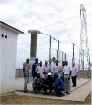
Fig. 6: The MAKOLA one-phase 50 kVA system. On the back, the 220 kV overhead line. On the front the LV house for the 230V distribution to the population.
Fig. 7: The MAKOLA 50 kVA system just switched on on April 17th, 2002.
Fig. 8: Breakdown counter installed at Makola.
6. TECHNICO-ECONOMIC ASPECTS
The one-phase system installed at MAKOLA is actually limited to 50 kVA. This is due to economical aspects. In fact the PLX245 is adapted from a 400 kV VT, with optimized windings in order to supply the 50 kVA rated power. We need such approach to use standard material to obtain a reasonable cost (about 1000 euros/kVA). It is possible to adapt the technology for any voltages over 70 kV up to 400 kV. But increase of power supply level would need specific investment a fig. 6: The MAKOLA one-phase 50 kVA system. On the back, the 220 kV overhead line. On the front the LV house for the 230 V distribution to the population.
7. SOCIOLOGICAL-ASPECTS
Since the installation of the electricity in that area, it becomes the place where marriages and some other cultural events are celebrated. These concern people from surrounding villages.
At the beginning people from Makola were not familiarized with the electricity. Nowadays, they cannot sustain the darkness. One day, there was a power-cut, the majority of the population were complaining, suddenly, the power came back they were very glad, so they applauded.
8. PROBLEMS RELATED TO LONG DISTANCES
If the distribution network is located several km far from the trunk line, we may easily adapt the system to get a several kV output from the PLX to avoid voltage drop troubles. Then a classical distribution power transformer would be needed near the load.
Some specific solution may be imagined. We had such a case in MAKOLA. One of the loads is the water adduction pump, located 3 km far from our installation. The power needed has been evaluated at 3 kVA for the 50 m deep source. The problem is the asynchronous motor start (with a 6 times nominal current need) for which the voltage must remain in the range +/- 10% around rated voltage. To avoid using large and expensive cables, we finally decided to install two small power transformers 1000/230 V to transfer the power on a specific line up to the adduction site. The transformers reactances are easily compensated by a 200 microfarad serie capacitor.
9. CONCLUSIONS
We have studied a new way to feed small loads from HV trunk lines in poor countries where electricity belongs to the high class of the population. The proposed system is a new kind of power transformer with SF6 gas insulation, based on existing technology used for instrument transformers. This system enables low cost LV power supply production, based on well tested technology with very few maintenance needed. This is particularly suited for 50 kVA loads in remote area (where HV lines must exist). Such a system has been designed and installed in Congo-Brazzaville from April 2002 in Makola. Until today (March 2006) there is no disturbance in the new load distribution which allow the local inhabitants to have access to new development, including drinking water, food conservation (fridge) and lighting for night activities. Unexpensive solution is now available to African villages crossed by high voltage lines.
ACKNOWLEDGEMENT
The author would like to acknowledge the professor Jean Louis Lilien of Liège university and the Belgian department for development cooperation (Minister of foreign affairs) AGCD and CUD which support the project. Local partners are also to be congratulated, ENSP, the technical department of Brazzaville University, ASCONES (a local non governmental organization) and the national electricity company (SNE).
REFERENCES
[1] B. G CHECO, ‘’Postes à couplage capacitif. (SCC)’’, Internal document Cegelec,
7151, rue Jean-Talon est. Anjou (Québec), Canada, 1995.
[2] P. G. LAURENT, ‘’Guide sur le calcul, l’exécution et la mesure des prises de
terre’’ R.G.E, vol. 81, no. 7, 8 et 9, pp 455-494 et pp 563-571, 1972.
[3] J. Maxwell Adams, “Electrical Safety: A guide to the causes and prevention of