Nat. Hazards Earth Syst. Sci., 14, 1677–1689, 2014 www.nat-hazards-earth-syst-sci.net/14/1677/2014/ doi:10.5194/nhess-14-1677-2014
© Author(s) 2014. CC Attribution 3.0 License.
Deformation information system for facilitating studies of
mining-ground deformations, development, and applications
J. Blachowski, W. Milczarek, and P. Stefaniak
Wroclaw University of Technology, Institute of Mining Engineering, Na Grobli 15, 50-421 Wroclaw, Poland
Correspondence to:J. Blachowski ([email protected])
Received: 26 July 2013 – Published in Nat. Hazards Earth Syst. Sci. Discuss.: 13 September 2013 Revised: – – Accepted: 30 April 2014 – Published: 3 July 2014
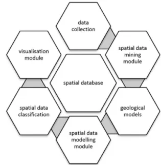
Abstract.The paper presents the concept of the deformation information system (DIS) to support and facilitate studies of mining-ground deformations. The proposed modular struc-ture of the system includes data collection and data visuali-sation components, as well as spatial data mining, modelling and classification modules. In addition, the system integrates interactive three-dimensional models of the mines and lo-cal geology. The system is used to lo-calculate various param-eters characterising ground deformation in space and time, i.e. vertical and horizontal displacement fields, deformation parameters (tilt, curvature, and horizontal strain) and input spatial variables for spatial data classifications. The core of the system in the form of an integrated spatial and attributive database has been described. The development stages and the functionality of the particular components have been pre-sented and example analyses utilising the spatial data ming and modellming functions have been shown. These in-clude, among other things, continuous vertical and horizontal displacement field interpolations, calculation of parameters characterising mining-ground deformations, mining-ground category classifications, data extraction procedures and data preparation preprocessing procedures for analyses in exter-nal applications.
The DIS has been developed for the Walbrzych coal mines area in SW Poland where long-time mining activity ended at the end of the 20th century and surface monitoring is neces-sary to study the present-day condition of the former mining grounds.
1 Introduction
The monitoring of active and former mining grounds with geodetic and other (e.g. remote sensing) techniques and anal-ysis of ground deformations due to mining activity are es-sential to study the behaviour of surface deformations and to produce maps of mining land-risk categories used to as-sess safety to the infrastructure, human population and the environment. The basic spatial information that is used for the identification and interpretation of mining-ground defor-mations are vertical and horizontal displacement fields and the related deformation parameters, tilt and curvature of the subsidence surface and horizontal strain (Popiolek, 2009).
The studies of mining-ground deformations require de-tailed and up-to-date spatial and attribute information on var-ious aspects of mining activity including geological models, mine plans, surface development, geodetic measurements, and other data that are used in complex interpretations of the observed and modelled changes of the ground surface.
determination of subsidence surfaces with interpolation tech-niques (Kowalczyk et al., 2010) or determination of mining-ground deformation parameters such as tilt, curvature or hor-izontal strain (Chrzanowski et al., 2012).
This paper introduces the concept of deformation infor-mation system (DIS) to facilitate studies of mining-induced ground deformations, especially in complex and complicated mining conditions and former underground mining areas. The system’s main components and functionality have been described on the example of the DIS for the former coal un-derground mines in the Walbrzych area in SW Poland.
2 The structure of the DIS
The deformation information system for augmenting stud-ies of mining-ground deformations is based on the modu-lar structure concept. The core of the system is made of the GIS database. The database system manages all of the col-lected and produced spatial and attributive data related to the mining activity and its influence on the surroundings. It in-cludes, among other things, mining plans (location, geome-try of underground workings, mining methods used and tem-poral mining activity data), locations of geodetic points and results of periodic geodetic measurements, land use and sur-face development data (Blachowski, 2008).
Then, the main components of the system are the spatial data mining module for knowledge discovery and data ex-traction with spatial and attribute query functions, the geo-logical modelling module realised with external software and integrated spatially with the system, the spatial data mod-elling module with data processing models for spatiotem-poral analysis and mapping of mining deformations and their characteristics (e.g. deformation parameters), and the data collection module based on terrestrial and remote sens-ing measurements carried out with geographic information technologies. The DIS is also connected with the multi-variate spatial data classification module. Another compo-nent allows interactive data presentation in the form of two-dimensional maps and three-two-dimensional visualisations. The general concept of the deformation information system has been shown in Fig. 1. In the following sections the develop-ment and functionality of its main components are described.
3 The Walbrzych coal mines
The idea to develop DIS has arisen from the need to study postmining-ground deformations in the former Walbrzych coal mines area in SW Poland. The extent of the former mines (Thorez, Victoria, Walbrzych), underground workings, shafts and built-up areas have been shown in Fig. 2. Under-ground mining of coal lasted there for several hundred years and ended in the late 1990s of the 20th century. The follow-ing minfollow-ing systems were used: long-wall and cavfollow-ing (pre-dominately) and long-wall with various forms of fill
(pneu-Figure 1.General structure of the deformation information system.
matic, dry, dry with material from dead drifts) (Piatek and Piatek, 2002). The hard coal industry has caused significant changes of the surface and its effects are visible in the local landscape to this day (waste dumps, settlement ponds, indus-trial objects, and the general urban system). Because of the observed ground changes the area requires continuous mon-itoring to analyse and assess the influence of the now ended mining on the present-day state of the ground and land de-velopment. For this purpose a detailed spatial database of the mines, geology, land use and development, geodetic net-works and their measurements have been required.
4 Development of the deformation information system The system’s database and the modelling, data mining and visualisation modules have been developed and implemented in the ESRI ArcGIS software environment. Their develop-ment and functionalities are described below. The remaining two components have been developed with the Geomodeller software (geological model) and artificial neural networks (spatial data classification module) and integrated with the DIS.
4.1 The DIS database
J. Blachowski et al.: Deformation information system 1679
Figure 2.Location of the former Walbrzych coal mines (Blachowski and Milczarek, 2011).
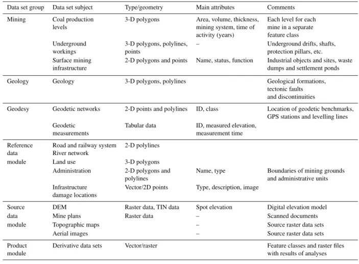
provided information on the geometry and location of coal levels and underground workings. Attribute data obtained from the mine plans included the mining system used and the time of the coal extraction. The geological documentations provided information on the geological and the geotechni-cal parameters. The other important data source includes the surveying logs with location of the geodetic benchmarks and the results of periodic levelling measurements. Topographic maps and aerial photographs provide information on land use and surface development over the years (1800–present). In addition, information on surface infrastructure damage is collected. The general structure of the system’s database is shown in Table 1. Only the core data sets have been listed. Detailed information on this part of the system can be found in Blachowski (2008). An important part of the database sys-tem is the product module that stores all of the feature classes representing results of spatial data analyses and results of analyses performed with external applications and imported to DIS. The structure of the database is open and can be ex-panded if necessary.
4.2 The geological model
The geological model of the Walbrzych coal basin in the part shown in Fig. 2 has been developed with the aim to obtain three-dimensional information on the geological structure in the former mining-grounds area and to use it to augment studies of natural and anthropogenic processes associated with mining and its effects on the ground surface. Because of the limitations of GIS in modelling 3-D objects, a spe-cialised Geomodeller software (Calcagno et al., 2008) has
been used for this purpose. It is a software application for advanced 3-D geological modelling. The preprocessing tasks associated with data preparation and postprocessing tasks as-sociated with model visualisation and integration have been done with the GIS software.
Data for the geological model included geological and mining maps (scale 1:5000) and 10 geological cross sec-tions. The geological model has been developed based on the equipotential field theory (Lajaunie et al., 1997; Chiles et al., 2004; McInerney et al., 2005; Calcagno et al., 2008). The theory assumes that the geological model is a combination of three types of data: geological formations, the limiting sur-faces and the fault sursur-faces cutting through them (Lajaunie et al., 1997). In this theory two assumptions must be met, the boundaries between geological formations in given locations and the spatial orientation of the particular layers are known. The model development has been divided into three parts. The first one concerned identification of the spatial extent of the model. This extent has been determined by availability of the data and the arrangement of the geodetic networks (GPS (global positioning system) and levelling) (Blachowski et al., 2009). The area of the model (7.2 km×6.7 km×0.8 km)
Table 1.The general structure of the DIS database.
Data set group Data set subject Type/geometry Main attributes Comments
Mining Coal production 3-D polygons Area, volume, thickness, Each level for each levels mining system, time of mine in a separate
activity (years) feature class
Underground 3-D polygons, polylines, – Underground drifts, shafts,
workings points protection pillars, etc.
Surface mining 2-D polygons and points Name, status, function Industrial objects and sites, waste
infrastructure dumps and settlement ponds
Geology Geology 3-D polygons, polylines Geological formations, tectonic faults and discontinuities
Geodesy Geodetic networks 2-D points and polylines ID, class Location of geodetic benchmarks, GPS stations and levelling lines Geodetic Tabular data ID, measured elevation,
measurements measurement time
Reference Road and railway system 2-D polylines data River network
module Land use 3-D polygons
Administration 2-D polygons and Name, type Boundaries of mining grounds
polylines and administrative units
Infrastructure Vector/2D points Type, description, image damage locations
Source DEM Raster data, TIN data Spot elevation Digital elevation model
data Mine plans Raster data – Scanned documents
module Topographic maps – Source raster data sets
Aerial images – Source raster data sets
Product Derivative data sets Vector/raster Feature classes and raster files
module with results of analyses
following form (1) (Calcagno et al., 2008):
T∗(p)−T∗(p0)= M X
α=1
uα
T (pα)−T
pα′
+ N X
β=1
νβ
∂T ∂uβ
pβ, (1)
whereT (p)is the scalar function of any pointp=(x, y, z)
in 3-D space,T∗(p)−T∗(p0)is the increment between two
points (p0andp),uα is the primary data (variable) weight, anduβ is the secondary data (variable) weight.
The model contains, from the top to the bottom, the Up-per Carboniferous formations in the form of the Zacler, the Bialokamienskie, and the Walbrzyskie layers. The last two layers contain coal levels (30 and 48, respectively). The bot-tom part of the model is made up of the Lower Carboniferous Kulm deposits. The general three-dimensional view of the model is shown in Fig. 3. The top boundary of the model is made up by the ground surface digital elevation model (DEM) and the bottom boundary has been set at−800 m be-low the sea level. The height coordinate system is the Kro-nsztadt 1986 system. In the last stage, the accuracy of the modelled geological objects has been verified. The
verifica-Figure 3.The three-dimensional numerical, geological model for the part of the former mining area shown with the black box in Fig. 2.
J. Blachowski et al.: Deformation information system 1681
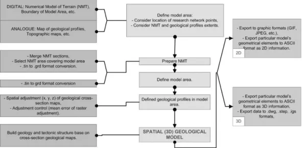
Figure 4.The generalised procedure of developing the spatial geological model (Milczarek, 2011).
The integration of the spatial geological model, as a whole or a selected part of the model, with mine plans, and other spatial information is carried out through exporting data to the shapefile format and loading them into the DIS database.
4.3 The spatial data mining module
With the aim to automate data query and data extraction pro-cedures used in studies of mining-ground deformations inter-active applications based on the visual basic for applications (VBA) programming language, ESRI ArcObjects platform (Burke, 2003) and the Microsoft .Net framework have been developed. The application is available as a toolbar that can be added to the graphical user interface of the ArcGIS soft-ware. It contains tools that enable data exploration in the DIS databases using the concept of the knowledge discovery in database (KDD) (Frawley et al., 1992). The data exploration tools include the find and selection operations that use any of the following criteria: mining system type, time of mining criteria, and location (Fig. 5). In response to the input cri-teria (e.g. long-wall with pneumatic fill mining system) the system selects and highlights coal parcels meeting the given criterion or criteria and returns a report. The results allow analysing and assessing the use of a given mining system, extent of mining, volume of extracted material as a function of time in a given coal production level or an area (multiple production levels).
4.4 The spatial data modelling module
With the same aim to automate complex and repeated spa-tial analysis procedures data geoprocessing models using the ArcToolbox application and the Python language scripting have been prepared based on the GIS data management func-tions and spatial data modelling funcfunc-tions including the map algebra concept (Tomlin, 2008). This method of spatial data processing generates new spatial data (i.e. map layers) based on input spatial data and numerical operations performed on them (Heywood et al., 2006). The spatial data are regarded as spatial variables and the applied cartographic functions are equivalent to algebraic operations (Tomlin, 2008).
The models developed in the DIS for deriving new spatial data based on the data stored in the geodatabase are available as a toolbar that can be added to the graphical user interface of the ArcGIS software or as geoprocessing models in the ArcToolbox application. The geoprocessing models use a se-quence of algebraic operations realised on vector and raster data sets. The following spatial data analysis operations are available on the additional toolbar: extract, slope, aspect and depth.
The extract model returns the area and volume of coal parcels mined, percentage of each mining system used and average value of surface subsidence inside boundaries of a user-defined rectangle.
Theslopemodel calculates inclination of a given coal pro-duction level. This operation requires conversion of 3-D vec-tor data to TIN (triangulated irregular network) representing elevation of the coal level above sea level and calculation of inclination. The results are returned as a raster whose cells represent value of slope.
Figure 5.The spatial data analysis application in the deformation information system.
The depth model calculates the depth of a selected coal production level below the ground surface. The raster surface representing depth of a coal level is calculated as a difference of the DEM and the raster with elevation of this coal level.
The other analytical functions for facilitating deformation analyses developed in the DIS are available as geoprocessing models and scripts. These are vertical and horizontal subsi-dence surface, deformation parameter surfaces (tilt, curva-ture, and horizontal strain) and the mining-ground category classifications.
The vertical displacement surface model calculates the continuous subsidence field from the scattered discrete mea-surement points (geodetic benchmarks) using the spline and the kriging interpolation functions. These models use the standard tools available in the GIS software. However, the subsidence surface is calculated for the optimised interpo-lation parameters; that is, those that generate the smallest estimation errors based on the results of cross-validation (Hofierka et al., 2007).
Thehorizontal displacement surface modelcalculates the continuous horizontal displacement field taking into consid-eration its non-linear characteristics. First the continuous dis-placement fields in thexandydirections are calculated using
the above-mentioned interpolation functions and the cross-validation method for estimation of the best-fitting interpola-tion surface. Then the final horizontal displacement field sur-face is obtained by combination of the displacement fields in thex andy directions. The input data for this
interpola-tion are the results of periodic GPS satellite observainterpola-tions (the measured horizontal displacements).
The tilt parametermodel uses the subsidence surface as the spatial variable input to calculate the continuous surface representing the tilt parameter (the first derivative of the sub-sidence surface).
Thecurvature parameter model uses the subsidence sur-face as the spatial variable input to calculate the
continu-Table 2. Risk classification of mining grounds (after Popiolek, 2009).
Mining TiltT Radius of Horizontal
ground [mm m−1] curvature strainε
category K[km] [mm m−1]
0 T ≤0.5 40≤ |R| |ε| ≤0.3
I 0.5< T≤2.5 20≤ |R|<40 0.3<|ε| ≤1.5
II 2.5< T≤5 12≤ |R|<20 1.5<|ε| ≤3
III 5< T≤10 6≤ |R|<12 3<|ε| ≤6 IV 10< T≤15 4≤ |R|<6 6<|ε| ≤9
V 15< T |R|<4 9<|ε|
ous surface representing the curvature parameter (the second derivative of the subsidence surface).
Thestrain parametermodel uses the continuous horizon-tal displacement field surface to calculate the continuous sur-face representing the horizontal strain parameter.
The resulting raster surfaces store the values of each pa-rameter that are used as input spatial variables to assign a mining-ground category (0 – least influence of mining to V – greatest influence of mining) using the Polish classification given for example in Popiolek (2009). The mining-ground category in terms of each parameter is given in Table 2.
An algorithm for calculation of the tilt and curvature pa-rameters is shown in Fig. 6.
4.5 The spatial data classification module
J. Blachowski et al.: Deformation information system 1683
Figure 6.Diagram of the geoprocessing model for the calculation of the tilt and radius of curvature parameters of the subsidence surface.
analysis of these factors. This information is associated with the factors having influence on the deformation of mining grounds, presence of certain regularities in the data and ex-istence of hidden characteristics of the deformation process. Thus, through construction of a behaviour model as a system of time-varying parameters, supported by a statistically rea-sonable set of examples, a better understanding of this phe-nomenon and prediction of deformation areas are possible. The spatial nature of this problem calls for the use of GIS technology.
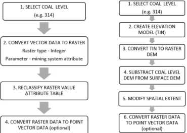
The models for deriving spatial data from the DIS geo-database used as input variables for SOM classifications with neural networks (in external software) and geographically weighted regression analyses (GWR) (in GIS software) are the coal level thickness, the mining system, the time of min-ing, depth below the ground and the slope. These models di-vide the analysed area into uniform cells of a given dimen-sion, e.g. 100 m×100 m, and assign values of the particular variable to the cells. The two example algorithms used to ob-tain layers representing the mining system parameter and the depth below the ground parameter are given in Fig. 7. The methodology is similar for the remaining procedures. In the first one shown in Fig. 7, the vector polygon data is converted to integer raster data where the raster pixels are assigned val-ues based on the valval-ues of the mining system attribute from the attribute table. The pixels falling outside the geometri-cal extent of the coal parcels are assigned a no-data value. The raster value attribute table (text codes) is then reclassi-fied to numerical values, e.g. the long-wall and caving min-ing system is assigned the value of 1 and the other systems 2, 3, and so on. The reclassified raster may be converted to point-vector data for further analyses. In the second proce-dure shown in Fig. 7, a DEM surface is created from the in-put vector polygon data representing the mined coal parcels in a given coal level. The DEM is converted to a raster that is
Figure 7.The simplified procedures to extract data for analyses, left – mining system variable, right – depth below the ground variable.
then subtracted from the DEM representing the surface, us-ing the map algebra subtract operation. The resultant raster storing depth below the surface values is modified to the spatial extent of the initial vector polygon data again using map algebra operations. The data can then be converted to point-vector data, the points representing values of individ-ual pixels.
These models automate data extraction from the DIS and data preprocessing for the purpose of various classifications such as self-organising maps and analyses using geographi-cally weighted regression functions to examine spatial rela-tionships between the input variables and the observed sur-face subsidence.
Figure 8. Three-dimensional visualisation of the coal thickness, mining system, time of mining, depth below the ground and slope variables derived for a selected coal production level and used for spatial data classification.
4.6 The data collection module
The geodetic and remote sensing measurement techniques used for collecting deformation and other data can be, in our opinion, regarded as another module of the system. The elec-tronic data transfer applications allow integrating the results of geodetic measurements with the DIS database. The mea-surement results used in the described case include archival and current precise and technical levelling realised in vari-ous parts of the Walbrzych area, GPS satellite observations carried out in the Walbrzych monitoring network, as well as part of the GEOSUD (GEOdynamics of SUDety Mountains) geodynamic network (Kontny et al., 2006).
4.7 The visualisation module
Another product of integrating and analysing the geometrical and attribute data collected in the database is an interactive, three-dimensional model of the underground mines in the Walbrzych area. The DIS allows two- and three-dimensional visualisations and interactive animations of the geometry of underground workings and production levels, as well as of the geological model. These models allow the development of smaller, local models for any part of the former mining area, as well as the development of vertical profiles. Ex-ample visualisations are shown in Figs. 9 and 3. The first one presents classification of the coal parcels according to the mining system used for a selected part of the Thorez mine. The second one shows a numerical geological model of part of the former mining area. The three-dimensional models are used as data sources for numerical modelling and for performing spatial analyses related to deformation stud-ies. The other forms of data visualisation are described in Sect. 5.
Figure 9.Three-dimensional visualisation of the selected under-ground workings and coal parcels classified according to the mining system used.
5 Application and discussion
The principal purpose of the DIS is to support and facilitate the studies of mining-related ground deformations in Wal-brzych’s former mining area with connection to regional geo-dynamics. These studies concern the period of mining (i.e. up to 1996), as well as the present-day (after the end of the mining activity) monitoring of the condition of the ground and its impact on the surface infrastructure based on repeated geodetic measurements in relation to the mining, geological and other data integrated in the system. Abstracts of publica-tions in Polish presenting development and enhancement of the DIS have been included in Appendixes A and B, respec-tively.
In addition, the mining and the geological models are used in finite element method modelling of ground deformations and deformation progress predictions and the system is used for visualisations of these numerical analyses (Blachowski et al., 2009; Milczarek, 2011; Blachowski and Milczarek, 2011).
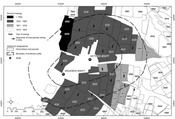
Examples of other types of analyses whose results are used in studies of the ground deformation caused by mining activ-ity are given below for the case of a single coal production level (#424/425) and inside a protective pillar established around two mining shafts.
The first one concerns analysis of mining activity in time in a given area. The results are shown graphically in Fig. 10, which presents the time of mining of the generalised coal parcels and the sequence of mining presented with arrows. In this case mining in the analysed area took place from 1824 to 1929.
J. Blachowski et al.: Deformation information system 1685
Figure 10.Mining activity analysis for the 424/425 coal production level within the boundaries of the protection pillar.
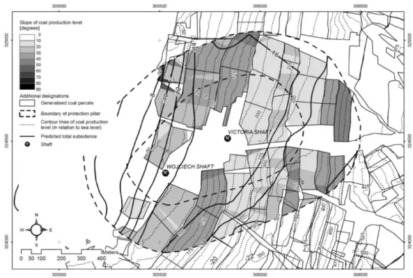
Figure 11.Slope analysis for the 424/425 coal production level within the boundaries of the protection pillar.
The third one concerns correlation of the predicted total subsidence (Kowalski and Jedrzejec, 2000) with the depth and the slope of the #424/425 production level. The result of this analysis is shown in Fig. 12. The long-wall and caving mining system was used in this case.
Figure 12.Subsidence analysis for the 424/425 coal production level within the boundaries of the protection pillar.
mining-terrain surface based on interpolated digital elevation models of old topographical surfaces (Blachowski and Mil-czarek, 2014) or assess the weight of mining-terrain defor-mation factors such as thickness, depth and slope of the ex-tracted coal deposits, as well as model mining-terrain subsi-dence in areas where surface elevation change measurements are unavailable with the geographically weighted regression (GWR) method based on tools available in GIS software suites. The latter have been presented in Blachowski et al. (2014).
6 Conclusions
The structure and methodology of developing the deforma-tion informadeforma-tion system, an indispensable means to support and facilitate mining-ground deformations studies, has been described. The presented approach uses a modular system structure that includes the following components: geodetic data collection, spatial data mining, spatial data modelling, geological modelling, spatial data classifications, and visu-alisations. The system integrates spatial and attributive data, as well as utilises interactive three-dimensional geological and mine models used for mining-ground deformation stud-ies. The DIS provides spatial data extraction and visualisa-tion funcvisualisa-tions and analytical funcvisualisa-tions for studies of the spa-tial and temporal changes of the mining activity in the past 200 years and the present-day monitoring of ground defor-mation in relation to the locations of the former mines. The selected analytical operations allow interpolation and
visu-alisation of mining subsidence surfaces including continu-ous horizontal displacement fields, calculation of the sur-face deformation parameters, i.e. tilt, radius of curvature and horizontal strain, classification of mining-ground categories based on the accepted (in Poland) mining-ground classifi-cations for any identified point in space, preprocessing and postprocessing of data for advanced analyses such as the spa-tial data classifications and numerical (FEM) modelling of ground deformations. In it also used to calculate and anal-yse historical mining terrain deformation and predict surface subsidence based on analysis of mining deformation factors with geographically weighted regression.
J. Blachowski et al.: Deformation information system 1687 Appendix A: Abstract of the paperGeographical
infor-mation system of the Walbrzych underground coal mines a way to improve effectiveness and accuracy of mining grounds deformation studies
Deformation studies of mining grounds involve gathering and working with large, complicated and diversified data sets. Most of this data has specified spatial reference. Man-aging and processing of such data is streamlined with GIS. In this paper, the structure of digital, geographical databases and associated attribute information used for deformation studies of the abandoned Walbrzych coal mines mining grounds has been presented. Functions and applications of the geoinformation system developed for supporting defor-mation studies and interpreting their results have been de-scribed and examples have been given.
Appendix B: Abstract of the paperAn enhancement of the geoinformation system for the former Walbrzych coal mines
Acknowledgements. The development of the system has been financed by the National Science Centre Project UMO-2012/07/B/ST10/04297 Development of a numerical method of mining ground deformation modelling in complex geological and mining conditions, and the scientific project no. S30035 Development of the model of secondary deformations on mining grounds carried out at the Institute of Mining Engineering of the Wroclaw University of Technology (Poland).
Edited by: N. Kerle
Reviewed by: M. Mergili and one anonymous referee
References
Blachowski, J.: Geographical Information System of the Walbrzych Underground Coal Mines a Way to Improve Effectiveness and Accuracy of Mining Grounds Deformation Studies, Scientific Papers of the Institute of Mining Engineering, Wroclaw Univer-sity of Technology, 34, 17–27, 2008 (in Polish).
Blachowski, J. and Ellefmo, S.: Numerical modelling of rock mass deformation in sublevel caving mining system, Acta Geodyn. Geomater., 9, 379–388, 2012.
Blachowski, J. and Milczarek, W.: Development and application of 3D geological model and geoinformation system for numer-ical modelling of ground deformations in abandoned under-ground coal mines, Proceedings IAMG 2011 Conference, 837– 851, doi:10.5242/iamg.2011.0000, 2011.
Blachowski, J. and Milczarek, W.: Analysis of surface changes in the Wałbrzych hard coal mining grounds (SW Poland) between 1886 and 2009, Geol. Q., 58, doi:10.7306/gq.1162, in press, 2014.
Blachowski, J. and Stefaniak, P.: An enhancement of the geoinfor-mation system for the former Walbrzych coal mines, Scientific Papers of the Institute of Mining Engineering, Wroclaw Univer-sity of Technology, 135, 5–21, 2012 (in Polish).
Blachowski, J., Cacon, S., and Milczarek, W.: Analysis of post-mining ground deformations caused by underground coal extrac-tion in complicated geological condiextrac-tions, Acta Geodyn. Geo-mater., 6, 351–357, 2009.
Blachowski, J., Milczarek, W., and Grzempowski, P.: Analysis of Mining Terrain Deformation Characteristics with Deformation Information System, EGU General Assembly 2014, Geophysical Research Abstracts, 16, EGU2014-7949, 2014.
Bogusz, J., Klos, A., Grzempowsk, I. P., and Kontny, B.: Modeling Velocity Field in Regular Grid in the Area of Poland on the Basis of the Velocities of European Permanent Stations, in press, Pure Appl. Geophys., doi:10.1007/s00024-013-0645-2, 2013. Burke, R.: Getting to Know ArcObjects: Programming ArcGIS with
VBA Programming ArcGIS with VBA, ESRI Press, 2003. Calcagno, P., Chilcs, J. P., Courrioux, G., and Guillen, A.:
Geolog-ical modelling from field data and geologGeolog-ical knowledge: Part I. Modelling method coupling 3D potential-field interpolation and geological rules, Phys. Earth Planet. In., 171, 147–157, 2008.
Chiles, J. P., Aug, C., Guillen, A., and Lees, T.: Modelling the ge-ometry of geological units and its uncertainty in 3D from struc-tural data: The potential-field method, Orebody Modelling and Strategic Mine Planning, 313–320, 2004.
Choi, J. K., Kim, K. D., Lee, S., and Won, J. S.: Application of a fuzzy operator to susceptibility estimations of coal mine sub-sidence in Taebaek City, Korea, Environ. Earth Sci., 59, 1009– 1022, 2010.
Chrzanowski, A., Blachowski, J., and Chrzanowski, A.: An assess-ment of mining on surface infrastructure in complex geologi-cal and mining conditions with the use of GIS methods, in: IV Konferencja Bezpieczenstwo i ochrona obiektów budowlanych na terenach gorniczych, Rytro, 17–19 October 2012 (in Polish). Doležalová, H., Kajzar, V., Souˇcek, K., and Staš, L.: Evaluation of
vertical and horizontal movements in the subsidence depression near Karvina, Acta Geodyn. Geomater., 3, 355–361, 2010. Frawley, W. F.,Piatetsky-Shapiro, G., and Matheus, Ch. J.:
Knowl-edge Discovery in Databases: An Overview, AI Magazine, 13, 57–70, 1992.
Heywood, I., Cornelius, S., and Carver, S.: An Introduction to Ge-ographic Information System, 3rd Edn., Pearson, Prentice Hall, Essex, England, 2006.
Hofierka, J., Cebecauer, T., and Šúri, M.: Optimisation of Interpola-tion Parameters Using Cross-validaInterpola-tion, in: Digital Terrain Mod-elling, Lecture Notes in Geoinformation and Cartography, edited by: Peckham, R. J. and Jordan, G., Springer, 67–82, 2007. Kim, K. D., Lee, S., and Oh, H. J.: Prediction of ground
subsi-dence in Samcheok City, Korea using artificial neural networks and GIS, Environ. Geol., 58, 61–70, 2009.
Kontny, B., Bosy, J., and Borkowski, A.: The use of permanent and epoch GPS coordinate time series in geodynamic investigations of Sudetes area – proposal of a new approach, Acta Geodyn. Ge-omater., 3, 31–38, 2006.
Kowalczyk, K., Rapinski, J., and Mroz, M.: Analysis of Verti-cal Movements Modelling Through Various Interpolation Tech-niques, Acta Geodyn. Geomater., 7, 399–409, 2010.
Kowalski, A. and J˛edrzejec, E.: Ground surface threats caused by former mining activity and closure of mines, in: Mining activ-ity and surface protection. Experiences from Walbrzych mines, edited by: Kowalski, A., Central Mining Institute, 343–366, 2010 (in Polish).
Lalajunie, Ch., Courrioux, G., and Manuel L.: Foliation fields and 3D cartography in geology: Principles of a method based on po-tential interpolation, Math. Geol., 29, 571–584, 1997.
Lee, S., Park, I., and Choi, J. K.: Spatial Prediction of Ground Sub-sidence Susceptibility Using an Artificial Neural Network, Envi-ron. Manage., 49, 347–358, 2012.
Malinowska, A.: A fuzzy inference-based approach for building damage risk assessment on mining terrains. Eng. Struct., 33, 163–170, 2011.
J. Blachowski et al.: Deformation information system 1689 Milczarek, W.: Analysis of ground surface changes after mining
ex-ploitation in the chosen region of the former Walbrzych basin, Ph.D. thesis, Wroclaw University of Technology, Poland, 2011 (in Polish).
Piatek, E. and Piatek, Z.: Summary of the history of the Lower Silesia coal mining 1434–2000, available at:
http://www.boehm-chronik.com/bergbau/gorn1434-2000.pdf, last access: 24 August 2012, 2002.
Popiolek, E.: Ochrona terenow gorniczych, Wydawnictwa AGH, Kraków, Poland, 2009 (in Polish).