Recebido em 30/08/2013, texto inal em 30/08/2013.
(Soldadura por mpulso magnético na vanguarda das aplicações industriais)
R. M. Mirandaa, B. Tomás a, T. G. Santosa, N. Fernandes b
a UNIDEMI,Departamento de Engenharia Mecânica e Industrial, Faculdade de Ciências e Tecnologia, Universidade Nova de Lisboa, 2829-516 Caparica, Portugal
b Omnidea, Faculdade de Ciências e Tecnologia, Universidade Nova de Lisboa, 2829-516 Caparica, Portugal
Abstract
Magnetic Pulse Welding (MPW) applies the electromagnetic principles postulated in the XIXth century and later demonstrated. In recent years the process has been developed to meet highly demanding market needs involving dissimilar material joining, specially involving dificult-to-weld materials. It is a very high speed joining process that uses an electromagnetic force to accelerate one material against the other, resulting in a solid state weld with no external heat source and no thermal distortions. A high power source, the capacitor, a discharge switch and a coil constitute the minimum equipment necessary for this process. A high intensity current lowing through a coil near an electrically conductive material, locally produce an intense magnetic ield that generates eddy currents in the lyer according to Lenz law. The induced electromotive force gives rise to a current whose magnetic ield opposes the original change in magnetic lux. The effect of this secondary current moving in the primary magnetic ield is the generation of a Lorentz force, which accelerates the lyer at a very high speed. If a piece of material is placed in the trajectory of the lyer, the impact will produce an atomic bond in a solid state weld. This paper discusses the fundamentals of the process in terms of phenomenology and analytical modeling and numerical simulation. Recent industrial applications are presented in terms of materials, joint conigurations and real examples as well as advantages and disadvantages of the process.
Key-words: Magnetic Pulse; Welding; Electromagnetic Welding; Cold Welding
Resumo: O processo de Soldadura por Impulso Magnético aplica os princípios do electromagnetismo postulados no século XIX e
veriicados mais tarde experimentalmente. Recentemente, o processo tem sido alvo de desenvolvimentos de modo a satisfazer requisitos do mercado, envolvendo ligações dissimilares ou de materiais difíceis de soldar. É um processo de elevada produtividade com tempos de soldadura muito curtos que usa a força electromagnética para acelerar um material contra o outro, resultando numa ligação no estado sólido sem calor adicionado externamente, nem distorções de origem térmica. Uma fonte de alta potência, um interruptor de descarga e uma bobina constituem os elementos fundamentais do equipamento. Uma corrente de elevada intensidade circulando através de uma bobina próxima de um material condutor produz uma corrente induzida, que por sua vez origina um campo magnético intenso que se opõe ao campo magnético original. O efeito desta segunda corrente movendo-se no campo magnético inicial é a geração de uma força de Lorentz que acelera o elemento “voador” a alta velocidade. Se se colocar um material no campo do elemento voador, no impacto produz-se uma ligação a nível atómico no estado sólido entre os dois elementos. Este artigo discute os fundamentos do processo em termos fenomenológicos, de modelação analítica e simulação numérica. Apresenta aplicações na industria em termos de materiais, coniguração de juntas, vantagens e desvantagens do processo.
Palavras chave: Soldadura por Impulso Magnético; Soldadura; Parâmetros do Processo; Soldadura Electromagnética; Soldadura
Fria
1. Introduction
Magnetic pulse welding is a process that emerged at the beginning of the ’70s as a spin off technology of nuclear energy
programs. The process was mainly developed for welding end
closures onto nuclear fuel rod holders [1]. The technique was
invented by Russian scientists from the Kurchatov Institute of Nuclear Physics. In USA, the Maxwell Laboratories Inc. (San Diego) have licensed this technology and built welding
equipment for Westinghouse Hanford Co., which fabricated a
nuclear reactor for the Energy Department. Other USA companies followed Maxwell Laboratories and further developed the
magnetic pulse welding process [1,2]. In the Aerospace industry
gases or radiation. It is a repeatable process that does not require additional reworks [1,3,4] dedicated to high mass production easy to robotize. The process brought up improvements in the quality
and productivity while reducing costs per part, by introducing revolutionary production designs there were not possible until
today [3,4], being suitable for large series production and for automated feeding system with low maintenance and quick changeover [3,9].
Fig.1 Scheme of impurity removal, Jetting
However, it has some disadvantages, such as: the part
to undergo plastic deformation, must have a good electrical
conductivity, otherwise, higher energy will be required and the cost of the process may be comparatively higher [3]; due to
the impact velocity and pressure, the inner material must have
suficient structural strength to withstand the impact without deformation [1], the security level must be kept high, and special safety precautions need to be implemented [10] due to the high
current intensity and voltage.
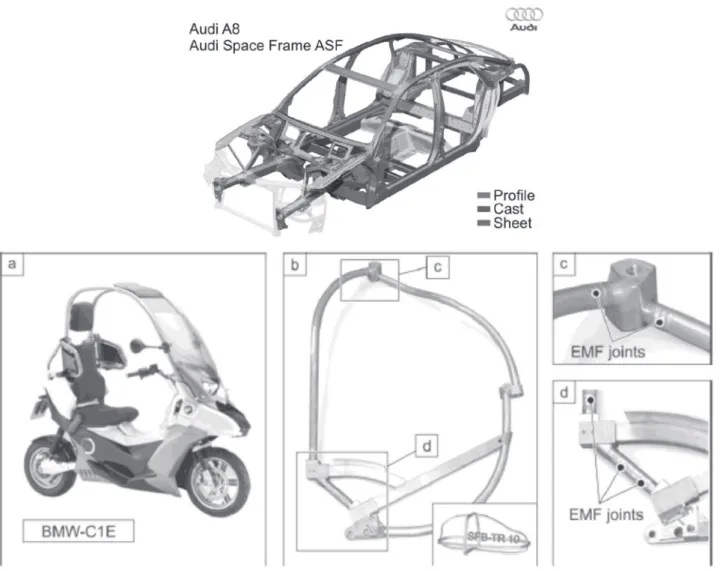
Table 1 summarises main examples of applications of
MPW in different industries [1,9], with particular emphasis on
automotive, aeronautic and nuclear ones. aircraft and spacecrafts. Automotive industry followed aiming at
reducing costs and increase production [3].
Magnetic Pulse Welding (MPW) is a cold process [3-6]
since the metallurgical bond is produced without fusion and therefore, mechanical and chemical properties of the material
do not undergo liquid-solid transformations. This process can be deined as a solid state welding one that produces a weld by
a high velocity impact of the parts under controlled conditions. During the process, materials are accelerated to a high speed, at which, when impacted, a metallic bond forms between the two
materials [3]. Welding between dissimilar materials is possible
since joining occurs by plastic deformation without melting.
According to [5,6] insipient local fusion is observed because the metals briely act like a liquid.
Magnetic pulse welding has never achieved a clear place amongst mainstream manufacturing processes. Though this
technique is known for a long time, there are still opportunities
of development and application, specially for joining multi
materials. For example, in applications requiring to combine
the strength of steel or titanium with the high electrical and thermal conductivities of aluminium or copper, fusion welding is possible though the very distinct mechanical and thermal
properties of these materials places several dificulties. Laser
and tungsten arc welding can be used but the productivity is
limited, as well as, the joint quality. Solid state processes are more and more applicable and amongst these, MPW, is seeing
an increasing interest.
One of the main advantages of MPW are related to the solid
state welding processes and the possibility of joining dissimilar materials while their mechanical and chemical properties will be almost maintained. These advantages rely in the fact that there is no heat introduced and no thermal distortions and it is a clean process where the jet formed in the high velocity impact between both materials remove any oxidation and dirty from the
surfaces (Fig.51) [1,3,7,8] that do not emit harmful fumes or
Table 1. Industrial applications of MPW
Nuclear Industry Aerospace Industry
• Closing caps
• End closers of nuclear fuel rods
• Metal canisters
• Nuclear fuel pins
• Lining of ammunition control rods
• Components of fuel pumps
• Tubular space frames
• Composites over wrapped Pressure Vessels
Automotive Industry Electrical Industry
• Space frames Drive shafts
• Reinforcing bands on oil ilters
• Components of air conditioning
• Fuel ilters
• Tubular seat components
• Electrical fuses
• Components of electrical motors
• Cable ducts
• Connectors to cooper cables
• Coaxial cable termination joints
Fig. 2. Examples of MPW applications
a) Audi space frame structure [64]; b) Structure of BMW-C1E [65]
2 - Fundamentals and Process Description
Magnetic pulse welding is a solid state process for joining metallic materials specially highly electrical conductive ones, that
uses a high intensity AC current to produce an electromagnetic ield to create an impact force to bond two metallic parts at an
atomic level.
Figs. 3 and 4 present a schema of the process, for plate and
tube, respectively. A high power source, the capacitor bank is
charged up to the energy required. This pulse generator provides AC electric current of high intensity in short pulses. The parts
are placed in the electromagnetic coil. The high intensity current
lowing through a coil near the electrical conductive material,
locally produce an intense magnetic ield that generates eddy currents in the lyer part according to Lenz law. The induced electromotive force gives rise to a current whose magnetic ield opposes the original change in the magnetic lux. The effect of
this secondary current moving in the primary magnetic ield is
the generation of a Lorentz force, which accelerates the lyer at a very high speed. This impact causes plastic deformation on the moving part, and under precisely controlled conditions an
atomic bond in a solid state weld is created between the two
materials. The impact velocity is above 300 m/s, therefore, this process is also called as high-velocity forming process [5].
Fig. 4. Schematic of MPW process [3]
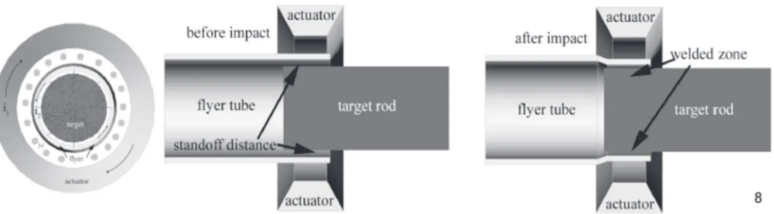
For the tubular joint coniguration the same principle is applied. The high-density magnetic lux created around the coil induces Eddy Current on the outer surface of a metal tube as shown in Fig. 5.
The main process parameters are: the discharge energy, the
standoff distance, the magnetic pressure, the impact velocity and the collision angle.
Discharge energy
Stored energy in the capacitor bank is discharged into the
coil and this energy is responsible for the movement of the lyer
metal. Discharge energy takes place in a very short time in the
range of a few microseconds in order to accelerate the lyer
metal so that it impacts the other part at a high velocity.
Increasing the charging voltage or the capacitance of condensers, increases the discharge energy and, thus, the
shearing strength of the welds will be enhanced [5]. In fact,
there is a threshold value of the discharge energy to produce
the weld. However, the correct energy must be used to avoid
exceeding critical strain rate of the material that can tear them. It means that for each material combination there is a minimum of energy necessary to join both materials, and there is a maximum
of energy before tearing or cracks to the welding process [6].
Standoff Distance
The standoff distance is the distance between parts prior to the discharge. This gap must exist at each welding, because,
when magnetic pressure is done on the lyer metal, it must have space to gain velocity and acquire kinetic energy that is
going to be transformed into impact energy. In order to have good welding between both metals, there is an optimum value of standoff distance, which varies according to the welding
materials. When standoff distance deviates from that value, the
velocity and the kinetic energy reduces, leading to a reduction in
the shearing strength and the width of the weld [5,6], as shown
in Fig. 6 for Al/steel joints.
If the standoff distance is low, collision takes place before
the lyer metal could reach the maximum velocity. On the other
hand, for higher standoff distance, the velocity drops to a lower value at the time of collision. In terms of discharge energy, the higher the gap, the higher should be the discharge energy in
order to obtain a good quality weld [5,6].
Fig. 6. Effect of standoff distance on shear strength. B – sample
cut from centre of welded zone; A and C – samples cut from edges of welded zone [6]
Magnetic Pressure
Magnetic pressure is one of the parameters responsible for
driving the lyer metal into the parent metal. Due to the induced Eddy Current, the magnetic pressure will oppose the magnetic ield from the coil and force the lyer metal to gain velocity
until collision. In order to have a successful bond, the magnetic
pressure must be high, otherwise the lyer metal will crash into
the parent metal with lower velocity and no bonding will occur.
High magnetic pressure can be obtained with high discharge energy or high frequency current.
When the standoff distance increases, the discharge energy
must increase to improve the magnetic pressure, maintaining
bonding quality. On the other hand, for a given standoff distance,
increasing the magnetic pressure will increase the tensile shear strength of the joint.
It was observed [13] that at each collision between the lyer
metal and the parent metal have a maximum value at different collision angles.
Impact Velocity
The impact velocity is inluenced by the energy and the
standoff distance. As shown in Fig. 7, the discharge energy and the velocity vary accordingly.
Fig. 7. Aluminium (lyer metal) velocity just before collision [5].
On magnetic pulse welding the impact pressure is very high
and consequently, the impact velocity is also very high, causing
plastic deformation at the interface between parts to weld. The
welding requires that both surfaces that are going to be joined
should be free of contamination, and thus, the high velocity of
the lyer metal plays an important role, because it will create
a jet that will remove any contaminants or oxidation particles
from both contact surfaces [5].
The impact velocity is directly correlated with the energy and discharge time from the capacitor, trough the coil into the
lyer metal. If the energy is transferred at low velocity, the lyer
workpiece will collapse and no bonding is produced.
Collision Angle
At the impact point, the shock waves travel in both metals
with a radial front, and an angle depicted in Fig. 8.
Fig. 8. Collision point [3]
The pressure peak is always at the collision point, because the shock wave travel speed is higher at the start point and decreases with time. Fig. 9 depicts the travel path of the shock waves from the collision point in the inner part and back to the surface, where the total path is the sum of X1 and X2. Z is the distance of the period, that is, the collision point is ahead of the shock wave interferences, and thus, in the collision starting point, the interface shows a wavy morphology while its amplitude decreases till de end of the weld due to shockwave damping.
Fig. 9. Shock wave propagation in MPW [14]
The collision point is where the pressure reach is higher
peak. Fig. 10-b) shows the shock wavelength formation. When the irst wave is generated, regardless of the inner part diameter, a Kelvin-Helmholtz instability mechanism is observed and waves are created periodically (Fig. 10-d)). Instability and new
collision points generate new shock waves. Thus, the following
wave is initiated by the interference continuity (Fig. 10-e)).
New interference can not be created while waves are formed by metals movements across the interface. Due to decrease of the propagation velocity with the weld progression, the shock wave interference meets the collision point further along and for this
reason, the wavelength increases (Fig. 10-f)). After some point,
Vc is so small that the interferences are ahead of the collision
If the part to be welded has different thicknesses and since stress waves travel both in the inner and outer parts, there might be more than one mode of interference. In this case, the
Kelvin-Helmholtz instability would be a multimode. If the impact
creates the right conditions of impact angle and velocity, jetting
is created and, consequently, welding takes place [3].
3 - Bonding Characteristics
Magnetic pulse welding produces either a wavy or waveless morphology at the interface of both materials. The precise shape is a function of the materials properties and the process
parameters. Fig. 11 shows the wavy interface of Al 7075 [3],
evidencing plastic deformation.
One most common welding consists on joining aluminium and stainless steel. The stainless steel (SS) has higher melting point and higher strength when compared to aluminium like AA6111. Due to their differences, when the welding takes place, the interface zone differs from one metal to the other. For the SS there is no change in grain morphology at the vicinity of
the wavy weld interface (Fig. 12). In AA6111 extensive plastic deformation was seen at the interface [15] due to the high-strain
rate exerted by the electromagnetic force. For this reason, it is
suggested that aluminium behave as a luid at a high strain-rate
deformation. The morphology of the interface is similar to that
of explosive welded joints [14,15]. Nevertheless, the amplitude
and wavelength of the interfacial wave are much smaller in magnetic seam welding.
Fig. 11. Macrograph of the bond area on a similar AA7075 join [3]
It is visible at Fig. 13 the intermediate layer that is formed between welding of A6111 and SPCC, where it is revealed that this layer is a mixture of ine crystal grains (indicated by arrows) and iner equiaxed crystal grains assumed as Fe-Al intermetallic
compound (indicated by dual arrows).
Fig. 12. AA6111 weld interface [15]
Fig. 13. Intermediate layer between A6111/SPCC [15]
Despite the temperature does not rise signiicantly, it was seen that increase [14] due to the jet and massive deformation of the surfaces, and in some cases, melting and solidiication occur (as in explosive welding). It was proven experimentally [14] that
the wavelength of interface waves is proportional to the free path of shock wave propagation in the inner part of the welded joint. This shock wave theory claims that the waves, due to impact, propagate through the metal parts creating periodic interference perturbation at the welding interface. Those interferences initiate
a Kelvin-Helmholtz instability that creates the interface waves.
To avoid formation of intermetallic pores and cracks, low pulse discharge energy should be limited.
Both, proile and amplitude of the waves after bonding, in the interface between lyer and parent metal are dependent on the shape of the lyer plate [16]. According to these researchers, three different kinds of lyer metals were tested: Flat, U and
V-shape. As result, the amplitude was higher for the Flat-shape metal and lower for the U-shape one.
4 – Analytical modelling and numerical simulation
Modelling of the process is not a simple issue, and several researchers attempted to establish process models. Basically, when the high current intensity is applied to the coil, a high
magnetic lux density B is suddenly generated and penetrates the
lyer metal. Eddy Currents (with a current density J) are created
at the surface of the lyer metal. As a result, an electromagnetic force of J×B will force the lyer metal until it collides into the parent metal. Accordingly to several researchers [27-19] MPW process can be replaced by an equivalent electrical circuit that
will help to understand and calculate variables like magnetic
ield or electromagnetic force. These calculations depend on the
weld geometry. Most common ones are tube to tube and plate to plate, and these have been the most extensively studied. The
Eddy Current J and the magnetic pressure P were obtained as
follows [6, 0]:
(1)
(2)
(3)
Where:
σ, is the electrical conductivity of the work piece (mΩ-1)
µ, is the magnetic permeability of the work piece (Hm-1)
δ, is the skin depth (m)
Β0, is the magnetic lux density at the lower surface (T)
Bi, is the magnetic lux density at the upper surface(T)
ƒ, is the frequency of transient current (Hz)
t, is the thickness of the conductor metal (m) P, is the magnetic pressure (Pa)
J, is the current density (A/m2)
From equation (1) it is possible to see that when using
materials with higher electrical conductivity, means higher Eddy
Currents, and as result, stronger magnetic pressure. According
to (2), the value of magnetic pressure increases and the depth
of the skin effect (3) decreases with the increasing the electrical conductivity. According to [21], the skin depth give us the value
of length towards the inside direction of the material at which the
current is reduced to 36%. Equation 2 can be used to calculate
the magnetic pressure.
The circuit theory allows calculating the pressure, the current and the depth effect along the workpieces, simulating
MPW process. The current takes the form of a damped sine and can be understood as a closed circuit: Inductance-Resistance-Capacitance (LRC) [17-19]. A magnetic pulse welding process
∂
∂
−
=
×
∇
t
B
is equivalent to a primary RLC circuit coupled with a secondary
RL circuit. A schematic model of the system analyzed is shown
in Fig. 14, where the RLC circuit (primary circuit) replaces the
capacitor bank and the coil.
Fig. 14. Representation of the equivalent circuit [20]
V0 is the initial voltage of the capacitor bank C is the capacitance of the capacitor bank Le1 is the total inductance of the primary circuit Re1 is the total resistance of primary circuit
M is the mutual inductance between the coil and workpiece I1 is the coil current
I2 is the equivalent induced current in the workpiece
Le2 is the workpiece equivalent inductance
Re2 is the workpiece equivalent resistance
Regarding the energy balance, the resulting force between
the magnetic i eld in the coil and the induced magnetic i eld in
the workpiece, normally is referred as the magnetic pressure.
The induced magnetic force and pressure is given by equations (4) and (5) [18,22]:
(4)
(5)
This analytical method was developed for calculating system inductance and electromagnetic pressure on the workpiece. The
analytical results were verii ed experimentally for the primary and induced current [20].
The peak current generated by a capacitor bank discharge
can be estimated for a standard LRC equations. So, Imax can be
estimated by equation (6) [17]:
(6)
Numerical calculation methods are very useful to optimize the process because they can decrease time and cost to run the process as well as to get a deeper insight into it. From the mechanical, thermal and chemical properties of the materials
2
2 0
B
P
=
µ
involved, simulations with dedicated softwares, either
commercial as MSC Dytran or LS-DYNA 980 or developed,
allow assessing welding parameters.
As an example Zhang et al. [23] tried to predict impact
velocities and temperature distribution along the bounded
interface in AA6061-T6 to Cu101 using the electromagnetism module available at DYNA. With this module it is possible to
simulate mechanical, thermal and electromagnetic experiments.
Fig. 15 presents the actuator, l yer and target involved. All
components were meshed using solid hexahedral elements.
Fi g. 15. Meshed three dimension [23]
and dissimilar welds of aluminium to copper, magnesium and
titanium, copper to bronze or nickel to titanium. When welding dissimilar metals the lyer metal should have high electrical
conductivity and the target should have higher yield strength to
avoid plastic deformation [8,25].
Fig. 18 depicts several examples of the relationship between material resistivity and skin depth. Copper and aluminium, due to their low resistivity, are the best ones to act as lyer material,
while steel and stainless steel are predominantly used as parent
metals, otherwise the discharge energy or frequency has to be
increased.
Table 2 resumes mechanical and thermal properties of most common materials used in MPW.
The simulation (Fig. 15) shows a rapid thermal cycle on
the bonded interface, the induced current change direction periodically and the maximum value for current density is on top and bottom edge of the welding area.
Fig. 17 presents the temperature at ive nods of lyer AA6061-T6 alloy. It was observed an increase on the ive nods around 200ºC
within 40µs.
Fig. 17. Temperature proile on AA6061-T6 at 2.4 kJ [23]
Based on the simulation, the temperature was seen to be below the melting temperature for each material involved, though, near the interface, the metals experienced a fast heating and cooling cycle. Local temperature increasing, favours the
metal luid low at a high strain rate, and at the same time
favours the wavy interface formation that contributes positively
to a good quality welding [23].
5 - Materials
Almost any material can be welded by MPW [4,24],
namely, similar joints of aluminium, copper, nickel and steel
Fig. 18. Skin depth Vs Electrical resistivity [8]
Welding of Similar Materials Ferrous
Dissimilar joining of steels to non ferrous alloys as Al, Cu or Ti is quite dificult by fusion welding and MPW is used instead with major advantages [26,27].
Non - Ferrous
As a light material, aluminium inds numerous applications
in transport and aerospace industries. Together with copper, since both alloys have a high electrical conductivity, they are
used in MPW as the lyer part. It was observed [28] that under
high strain rates, aluminium ductile behaviour increases, which facilitates magnetic welding similarly to Ti alloys that exhibit excellent corrosion resistance associated to high mechanical resistance. Magnesium alloys is gaining interest in the automotive and aeronautic industries, mainly, because of their high weight to resistance ratio since Mg is the lightest structural
material [28,29,30]. It has been tested under high velocity welding technologies, and MPW is feasibility in Mg alloys [30]
where ductility and formability increase at high strain rates.
Similar welding of aluminium alloys AA1050 [5], AA6063 [21] and AA6061 [28] in plates or tubes have been studied by
several research groups in order to assess the effect of welding parameters on the bonded length, the interface morphology and the overall mechanical strength. In solid state welding these alloys do not exhibit major weldability problems.
Welding of Dissimilar Materials
Dissimilar welding of AA1050 to Ti and AZ91 alloys in sheets of 0.5 to 1 mm thick was studied using two capacitor
banks in parallel of 100 µF/10kV, with an inductance of 0.02
µH [4, 30], with a energy discharge of 1.2 kJ and the maximum current measured was of 150 kA. A wavy like morphology of
the interface was observed between Al / Fe, Ti and Mg as shown
in Fig. 19) with a good bonded interface free of intermetallics or
defects, which is a remarkable result.
When welding 1mm thick aluminium to 0.25 mm thick
stainless steel, the capacitor bank was charged with 10 kJ at 10
kV. A copper coil was used with an inductance of 0.74 nH. The
Fig. 19. Bonding area of different dissmilar joints [4]
total inductance of the circuit was 0.7 µH. The parameters were adjusted to get a frequency of oscillating current of 18.5 kHz, in order to ensure that skin depth on the lyer material (aluminium) was less than its thickness. Fig. 20 shows the tensile shear
strength variation with the standoff distance.
Stand off distance
Fig. 20. Welding results of Al/SS [7] “A” and “C” correspond to samples cut from the edge of the bonded area and “B” to
samples cut from the middle
As expected, it was observed [6] that the samples from the
middle of the weld had a higher shearing strength due to a higher
penetration of the magnetic ield in the centre of the welded length than near the edges, but also because the current lowing
through the sheets change direction at the edges. This weakness
of the magnetic ield will decrease the magnetic pressure on the lyer material, so, as a result, the bonded area has lower shear
strength. For a optimum value of standoff distance the strength
is maximum, when above or below the kinetic energy of the lyer
metal is reduced, since the velocity decreases and so does the magnetic pressure. In order to compensate the deviation, more
energy is required to obtain the same result. The microstructure
of the bonded interface shows a good continuous weld between aluminium and stainless steel free of defects (Fig. 21).
Welding Copper (DHP R290) to Brass (CuZn39Pb3) [31]
a bonded interface similar to explosive welding was seen with a brittle interlayer despite the fact that the temperature do not
increase signiicantly (Fig. 23). However, it has been veriied [32] that the jet will increase the temperature between metals,
angle should be decreased. In fact, the jet is dependent on the impact angle, the discharge energy and the impact velocity.
Fig. 21. Aluminium and Stainless Steel interface [6]
Fig. 22. Copper/Brass Boundary [31]
An interesting study was conducted on welding pure Al
(99.5) to TiAl6V4 aiming to investigate the inluence of impact velocity on bonding these two dissimilar metals [30]. It was concluded that in the range of 10 m/s to 25 m/s, there was no
bonding on the atomic scale, and above this value some sections
of the samples were welded. Fig. 23 shows that an increase of
the impact velocity leads to a higher ratio of the welded area and contact surface.
Micrograph analysis at the interface between both metals,
with an impact velocity of 130 m/s show micro fractures in the
aluminium, running parallel to the contact surface of the weld (Fig. 24).
When a threshold value of impact velocity is exceeded, there
is a deterioration of the joint. For this combination of metals,
the optimum value relies between 100 m/s and 130 m/s. A
similar study was performed on tubes of aluminium with 20 mm
diameter and 1 mm thick and titanium with 15 mm diameter and 2.5 mm thick. Both workpieces were positioned coaxially
in the compression coil with an initial gap of is 1.5 mm. After
some experiments, the desirable impact velocity was established
to be around 100 m/s with a energy of 500 J. For a discharging
energy of 1.000 J there was a wavy interface of 4 and 6 mm in amplitude. Increasing this parameter the bonded interface was
more lat and he weld was successful.
Fig. 23. Impact velocity Vs Welded surface [30]
Fig. 24. Bonding interface [30]
Conclusions
Magnetic Pulse Welding has been growing since the 70’s and
there is an increasing interest in the welding process in several industrial sectors.
It is a cold welding process in which two metal surfaces in placed in close contact by the effect of a high speed electromagnetic force produced in a short pulse capacitor.
There is no heat developed in the interfaces due to the very short duration of the process in the range of few tens of millisecond
The impact velocity is proportional to the current intensity,
the distance between the plates and the voltage. When impact
the bonding is the result of good angle impact [13].
When current frequency increases, magnetic pressure will increase. Higher frequencies have larger magnitude with short peak time period, but, for lower frequency the pulse will decrease during more time. Thus, deformation of the lyer metal will be quicker for high frequencies, due to higher discharge current frequency results in quick damping of the current. It is possible to conclude that when a lyer metal has lower conductivity, the process must have higher frequency and large wall thickness (for lyer metal) resulting on high magnetic pressure. Thus, the higher is the electrical conductivity, less energy is required to have collision and create bonding. For example: welding
between aluminium and copper it was necessary lower electrical
and thermal resistance to achieve strong joints. Comparing with
welding of aluminium to titanium and steel, it was needed more
energy to achieve high joints [34].
Standoff distance as optimum value for welding, and when it deviates discharge energy must increase. If the gap diminished
more energy is needed to give more velocity to the lyer metal.
On the other hand, if the gap increases, more energy is needed
because the lyer metal has a bigger distance to go trough before
impact into parent metal.
Welding between dissimilar metals is not an issue for MPW technique providing both metals are electrical conductors. When
the metals involved have higher tensile or yield strength the discharge energy must be higher, and the opposite is also valid. Nevertheless, the success of getting good welding between
metal sheets, tubes or other conigurations depends mainly on the discharge energy, standoff distance, thickness of the lyer
metal and parent metal, material of the metal and coil geometry and strength.
Increasing applications exist especially in automotive industry in dissimilar joining of structural resistant light alloys
[34,35].
References
[1] Weber, Austin. The Cold Welding Process is being
used for more and more high-volume applications. Assembly Magazine, (2002).
[2] Glouschenkov, V.A., Grechnikov, F.V., Mayshev, B.S.. Pulse-Magnetic Processing Technology when making parts
units of Aerospace Engineering. Journal de Physique IV. (1997) Vol. 7, Colloque C3, Suplement of Physic Journal 111. pp. C3-45 to C3-48.
[3] Shribman, V.. Magnetic Pulse Welding of Automotive
HVAC Parts. Pulsar - Magnetic Pulse Solutions, (2007) pp. 1-31.
[4] Shribman, V., Blakely, Michael. Beneits of the Magnetic
Pulse process for Welding Dissimilar Metals. Welding Journal, (2008) Vol. 87 nº 9, pp. 56-59.
[5] Kore, S.D., Date, P.P, Kulkarni, S.V.. Effect of Process
Parameters on Electromagnetic Welding of Aluminum Sheets. International Journal of Impact Engineering, (2006) Vol. 34, pp. 1327-1341.
[6] Kore, S.D., Date, P.P, Kulkarni, S.V.. Electromagnetic
Impact Welding of Aluminum to Stainless Steel Sheets. Journal
of Materials Processing Technology, (2008) Vol. 208, pp.
486-493.
[7] Watanabe, Mitsuhiro, Kumai, Shinji. Interfacial
morphology of magnetic pulse welded aluminum/aluminum and copper/copper lap joints. Journal of Japan Institute of Light
Metals, (2009) Vol.59, nr.3, pp.140-147.
[8] Zittel, G.. A historical review of high speed metal
forming. Presented at the 4th International Conference on High Speed Forming, Ohio USA (2010), pp. 12-25.
[9] Livshiz Y., Gafri O.. Technology and equipment for
industrial use of pulse magnetic ields. Pulsar, (1999), pp.
475-478.
[10] Neugebauer, R., Loeschmann, F., Putz, M., Koch, T., Laux, G.. A production oriented approach in electromagnetic
forming of metal sheets. 2th International Conference on High Speed Forming, Dortmund, Germany (2006), pp. 143-153.
[11] Kochan, Anna. Magnetic pulse welding shows potential for automotive applications. Assembly Automation, (2000) Vol.
20, nr.2, pp. 129-131.
[12] V. Psyka, D. Risch, B.L. Kinsey, A.E. Tekkaya, M.
Kleiner, Electromagnetic forming—A review”, Journal of
Materials Processing Technology 211 (2011) 787–829
[13] Serizawa, Hisashi, Shibahara, Isao, Rashed, Sherif,
Murakawa, Hidekazu. Numerical Study of joining process in Magnetic Pressure Seam Welding. Joining and Welding Research Institute, (2009) Vol. 38 nº 1, pp. 63-68.
[14] Shribman, V., Ben-Artzy, A., Stern, A., Sadot, O.. Wave
formation mechanism in magnetic pulse welding. International Journal of Impact Engineering, (2009) Vol. 2, pp. 1-8.
[15] Aizawa, T.,Lee, Kwang-Jin, Kumai, Shinji, Arai, Takashi. Interfacial microstructure and strength of steel/aluminum alloy lap joint fabricated by magnetic pressure seam welding.
Materials Science & Engineering A, (2007) Vol. 471, pp.
95-101.
[16] Chizari, M., Al-Hassani, S., Barret, L.. Effetc pf lyer
shape on the bonding criteria in impact welding of plates. Journal of Materials Processing Technology, (2009) Vol.209,
pp. 445-454.
[17] Daehn, G.S.. High Velocity Metal Forming. ASM
International, (2006) Vol. 14B, pp. 405-418.
[18] Geier, M., Paese, E., Pacheco, J.L., Homrich, R.P., Ortiz,
J.C.. Mathematical Modeling of na Electromagnetic Forming System with lat Spiral Coils as Actuator. 4th International Conference on High Speed Forming, Columbus, Ohio, USA
(2010), pp. 219-228.
[19] Kempen, S., Peier, D.. An Optimised High Current
Impulse Source. 1st International Conference on High Speed Forming, Dortmund, Germany (2004), pp. 295-304.
[20] Zhang, P., Kimchi, M., Shao., H., Gould., J.E., Daehn
G.S.. Analysis of the Electromagnetic Impulse Joining Process
with a Field Concentrator. Edison Welding Institute, (2004) Vol. 712, pp. 1253-1258.
[21] Uhlmann, E., Ziele, A.. Modelling pulse magnetic
welding processes – an empirical approach. 4th International
Conference on High Speed Forming, Columbus, Ohio, USA
(2010), pp. 108-116.
[22] Geier, M., Paese, E., Pacheco, J.L., Homrich, R.P., Ortiz,
Thin Metal Sheets. 4th International Conference on High Speed Forming, Columbus, Ohio, USA (2010), pp. 264-273.
[23] Zhang, Y., L’Eplattenier, P., Daehn, G.S., Babu, S..
Numerical simulation and experimental study for magnetic
pulse welding process on AA6061-T6 and Cu101 sheet. ASM International, (2009), pp.715-720.
[24] Werdelmann, P., Rosendahl, J., Peier, D., Kulig, S..
Assessing the effective energy for magnetic forming processes
by means of measurements and numerical calculation. 3rd International Conference on High Speed Forming. Dortmund, Germany (2008), pp. 299-306.
[25] - Zhang, Y., Babu, S., Prothe, C., Blakely, M., Kwasegroch,
J., Laha, M., Daehn, G.S.. Application of high velocity impact welding at varied different length scales. Journal of Materials Processing Technology. Elsevier (2010). In Press.
[26] Schaefer, R., Pasquale, P.. Electromagnetic pulse forming
technology. Keys for allocating the industrial market segment.
4th International Conference on High Speed Forming, Dortmund Germany (2010), pp. 26-35.
[27] Onosovskii, E.V., Chucakov, V.A., Sokolov, V.I.,
Saprygin, V.D.. Magnetic impulse welding of thin-walled
aluminum-steel adapters. Plenum Publishing Corporation, (1984) nr. 11, pp. 25-26.
[28] El-Magd, E., Abouridouane, M.. High Speed Forming of
the Light-Weight Wrought Alloys. 1st International Conference on High Speed Forming, Dortmund, Germany (2004), pp.
13-22.
[29] Prasad, NK, Ram, Y, Sabharwal, TP, Pathak, Kavindra,
Kumar, Manish, Matkar, AW, Rajawat, R K.. UHV compatible Al to SS joining through ElectroMagnetic forming technique. Journal of Physics, (2008) Conferences Series Vol. 114, pp. 1-6 International Symposium on “Vacuum Science and Technology”.
[30] Ulacia, I., Arroyo, A., Eguia, I., Hurtado, I., Gutiérrez,
M.A.. Warm Electromagnetic Forming of AZ31B Magnesium Alloy Sheet. 4th International Conference on High Speed
Forming, Dortmund Germany (2010), pp. 189-197.
[31] Faes, K., Baaten, T., Waele, W. De, Debroux, N..
Joining of copper to brass using magnetic pulse welding. 4th
International Conference on High Speed Forming, Dortmund
Germany (2010), pp. 84-96.
[32] Iwamoto, Nobuya, Tabata, Sanetoshi, Takeuchi, Toshiaki.
Pressure Welding of Aluminum to Titanium, Joining and Welding Research Institute, (1976) Vol. 5 nº 1, pp. 63-66.
[33] Marya, M., Marya, S., Priem, D.. On the characteristics
of electromagnetic Wells between Aluminium and other metals and alloys. International Institute of Welding, July, Japan (2004),
Doc. IX-2141-04.
[34] Golovaschenko, S.. Electromagnetic forming and joining
for automotive applications. 2nd International Conference on High Speed Forming, Dortmund, Germany (2006), pp. 215-220.
[35] Weddeling C., Woodward, S., Nellesen, J., Psyk, V.,
![Table 1 summarises main examples of applications of MPW in different industries [1,9], with particular emphasis on automotive, aeronautic and nuclear ones.](https://thumb-eu.123doks.com/thumbv2/123dok_br/18858682.417529/2.955.523.882.289.450/summarises-examples-applications-different-industries-particular-automotive-aeronautic.webp)
![Fig. 8. Collision point [3]](https://thumb-eu.123doks.com/thumbv2/123dok_br/18858682.417529/5.955.77.448.576.851/fig-collision-point.webp)
![Fig. 11. Macrograph of the bond area on a similar AA7075 join [3]](https://thumb-eu.123doks.com/thumbv2/123dok_br/18858682.417529/6.955.88.872.119.548/fig-macrograph-bond-area-similar-aa-join.webp)
![Fig. 13. Intermediate layer between A6111/SPCC [15]](https://thumb-eu.123doks.com/thumbv2/123dok_br/18858682.417529/7.955.78.460.120.281/fig-intermediate-layer-between-a-spcc.webp)
![Fig. 16. Current density of the l yer plate at 2.4 kJ [23]](https://thumb-eu.123doks.com/thumbv2/123dok_br/18858682.417529/8.955.510.874.322.646/fig-current-density-l-yer-plate-kj.webp)
![Fig. 17. Temperature proile on AA6061-T6 at 2.4 kJ [23]](https://thumb-eu.123doks.com/thumbv2/123dok_br/18858682.417529/9.955.85.451.263.509/fig-temperature-proile-aa-t-at-kj.webp)
![Fig. 20. Welding results of Al/SS [7] “A” and “C” correspond to samples cut from the edge of the bonded area and “B” to](https://thumb-eu.123doks.com/thumbv2/123dok_br/18858682.417529/10.955.514.878.467.685/fig-welding-results-correspond-samples-edge-bonded-area.webp)
![Fig. 21. Aluminium and Stainless Steel interface [6]](https://thumb-eu.123doks.com/thumbv2/123dok_br/18858682.417529/11.955.79.449.163.440/fig-aluminium-and-stainless-steel-interface.webp)
